Unit 1
Fundamentals of 3D Modelling
Q1) Explain the life cycle of a product.
A1) Figure shows the life cycle of a typical product. The product begins with a need which is identified based on customers’ and markets’ demands. The product goes through two main processes from the idea conceptualization to the finished product: The design process and the manufacturing process.
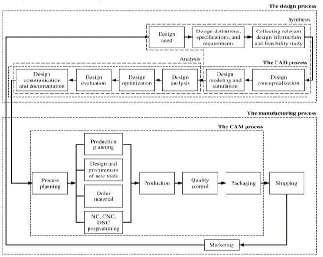
Fig. Typical Product Life Cycle
Design process: The product goes through two main processes from inception to a finished product: the design process and the manufacturing process. Synthesis and analysis are the two main subprocesses of the design process.
Synthesis: The philosophy, functionality, and uniqueness of the product arc all determined during synthesis. During synthesis, a design takes the form of sketches and layout drawings that show the relationship among the various product parts. These sketches and drawings can be created using a CAD/CAM system or simply hand-drawn on paper. They are used during brainstorming discussions among various design teams and for presentation purposes.
Analysis: The analysis subprocess begins with an attempt to put the conceptual design into the context of engineering sciences to evaluate the performance of the expected product. This requires design modeling and simulation. An important aspect of analysis is the "what if' questions that help us to eliminate multiple design choices and find the best solution to each design problem. The outcome of analysis is the design documentation in the form of engineering drawings (also known as blueprints).
Manufacturing Process: The manufacturing process begins with the process planning and ends with the actual product. Process planning is considered the backbone or the manufacturing process since it attempts to determine the most efficient sequence in which to produce the product. A process planner must be aware of the various aspects of manufacturing to plan properly. The planner typically works with the blueprints and may communicate with the design team to clarify or request changes in the design to fit manufacturing requirements. The outcome of the process planning is a production plan, tools procurement, material order, and machine programming. Other special manufacturing needs such as design or jigs and fixtures or inspection gages are planned.
Q2) What is product life cycle management? Explain its need.
A2) Product life cycle Management (PLM) is a system of managing the entire life cycle of the product.
Product lifecycle management (PLM) is the Business Strategy of managing the entire lifecycle of a product from its conception, through design and manufacture, to service and disposal.
It Supports the Extended enterprise (Customers, Design and supply partners). PLM Spans from the Concept to the last stage – the life of a product or plant.
Need of PLM:
Q3) Define Computer Aided Design. Give its features.
A3) Computer Aided Design:
“The use of computer systems to assist in the creation, modification, synthesis, analysis and optimization of a design of any product, machine or component of machine is defined as Computer Aided Design.”
Features of CAD
Q4) Give the scope of CAD/CAM
The CAD process and its tools utilize three disciplines: geometric modeling, computer graphics, and design. The CAM process utilizes the disciplines of CAD itself, manufacturing, and automation.
At the core of the CAD and CAM processes is a geometric model of the product under design. Activities of the CAD process include mass properties, finite element analysis, dimensioning, tolerancing, assembly modeling, generating shaded images, and documentation and drafting. Activities of the CAM process include CAPP, NC programming, design of injection molds, CMM verifications, inspection, assembly via robots, and packaging.
The CAD process and its tools utilize three disciplines: geometric modeling, computer graphics, and design. The Cam utilizes the discipline of CAD itself, manufacturing and automation. Figure below shows these disciplines.
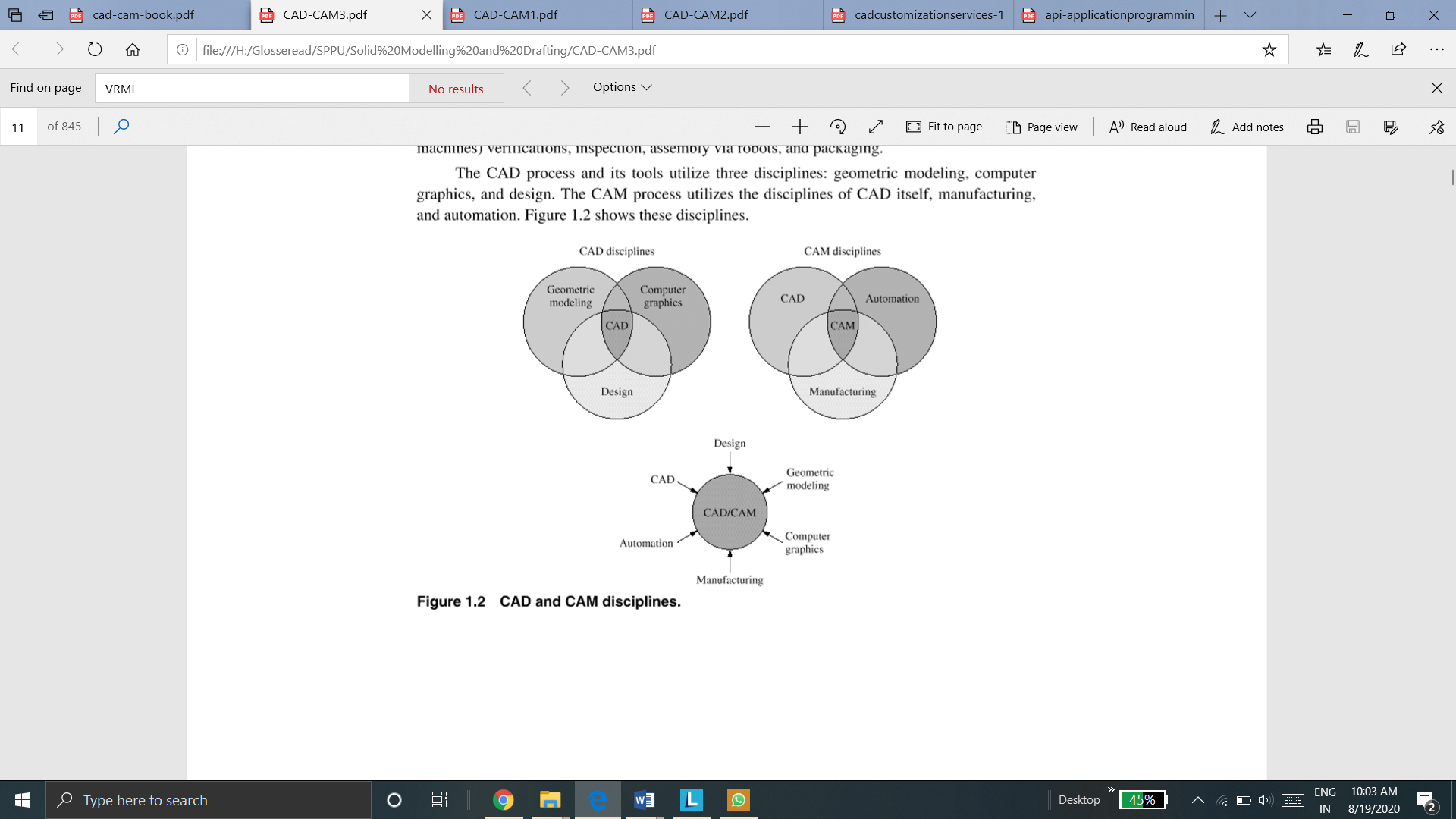
Q5) Which CAD tools are used in design process of product cycle?
A5) The various CAD tools that are used to perform various steps in design process is given below:
CAD system offers many sketching commands/tools, which allow us to create various 2D shapes using geometrical entities such as lines, circles, arcs, fillets, rectangles and chamfers. All CAD systems offer these sketching tools.
2. Modelling tools (3D operations)
We take the sketches that we create and apply various 3D operations to them to obtain various features and surfaces which we call CAD models. CAD system offer many 3D operation for both solid and surfaces such as extrusion, revolve, cut, holes, ribs, chamfers, fillets, sweeps and lofts. These commands can be selected using the menu-bar or toolbar approach. It is important to know that 3D operations may require more than one sketch I order to completely define the feature or surface.
3. Viewing command
Once the object is created using 3D operations, or while in the process of creating models and sketches, CAD system allow us to view those models in many different ways. Most of the viewing operations on CAD system can be classified into three groups: view orientation, view modes, and view manipulations.
View orientation includes standard views such as front, top, right, and isometric. They basically align the object on screen in a way that displays selected views.
View modes allow us to change the display of the model to different types such as wireframe, hidden, or shaded.
View manipulation allow us to dynamically rotate, pan, and zoom the model to gain better control over its viewing.
4. Productivity tools
All CAD system provide certain productivity tools/features that reduce the time required to create a model and also increase the accuracy of the model. Examples of such productivity tools are geometric modifiers, geometric arrays and grids.
5. Management tools
CAD system provide management tools so that a user can group together the entities of similar nature, which in turn assists in editing, visualization, and efficient access to CAD models. Some management tools that CAD system offer are layers and colors.
6. Editing tools
When one needs to retrieve the model later by opening its file to resume its modelling by performing new CAD/CAM operations.These operations include either editing the existing model definition or adding new entities to it.
7. Coordinate system and sketch plane tools
Coordinate system and sketch plane are the most important concepts in a CAD system. They are used to input, store and display model geometry and graphics. The three coordinate systems that achieve these tasks are Model coordinate system, working coordinate system, and screen coordinate system.
Q6) Explain different types of software modules
A6) There are considerable numbers of applications for the various existing CAD/CAM systems. For example, there are mechanical, electrical, and architectural CAD and CAM products. An inspection of these various systems reveals that they have a generic structure and common modules. Awareness of such structure and modules enables users to better understand system functions for both evaluation and training purposes.
The major available modules are:
The operating system (OS) module provides functions for interacting with the operating system. This module provides a portable way of using operating system dependent functionality. This model helps the CAD/CAM system or software to interact with the operating system of the computer.
The geometric module is the heart of a CAD/CAM system. It provides users with functions to perform geometric modeling and construction. Editing and manipulation of existing geometry, drafting and documentation. The typical modeling operations that users can engage in arc model creation, cleanup, documentation, and printing/plotting. Shaded images can be generated as part of model documentation.
The applications module varies from one software system to another. However, there are common applications shared by most CAD/CAM systems. Mechanical applications include mass property calculations, assembly analysis, tolerance analysis and synthesis, sheet metal design, finite element modeling and analysis, mechanisms analysis, animation techniques, and simulation and analysis of plastic injection molding. Manufacturing applications include CAPP, NC, CIM, robot simulation, and group technology.
The programming module allows users to customize systems by programming them to fit certain design and manufacturing tasks. A CAD/CAM system requires advanced knowledge of the system architecture, its database format, and a high-level programming language such as C, C++, Java, Scheme, or others.
The communications module is crucial if integration is to be achieved between the CAD/CAM system, other computer systems, and manufacturing facilities. It is common to network the system to transfer the CAD database of a model for analysis purposes or to transfer its CAM database to the shop floor for production. This module also serves the purpose of translating databases between CAD/CAM systems using graphics standards such as IGES and STEP.
The collaborative module is emerging as an outcome of the widespread of the World Wide Web and the Internet. This module supports collaborative design. Various design teams in different geographical locations can work concurrently on the same part, assembly, or drawing file in real time over the Web. One team can make changes that other teams can view and accept or reject.
Q7) Explain feature and sketch-based modelling approach
A7) Now-a-days, feature based modelling is most widely used approach of creating 3D model.
Feature is defined as the combination of shape and operation to build the parts.
Shape is a 2D sketch.
Operation is an activity that converts the sketch into a 3D shape.
Steps in Feature and sketch based modelling are
First step is to create the shapes or sketches. A shape is a 2D profile or a cross-section.
ii. Create features
Apply feature operations to the sketches created in previous step. Different feature operations are extrude, revolve, sweep, loft, etc.
iii. Combine features
Different features are combined to form a 3D model.
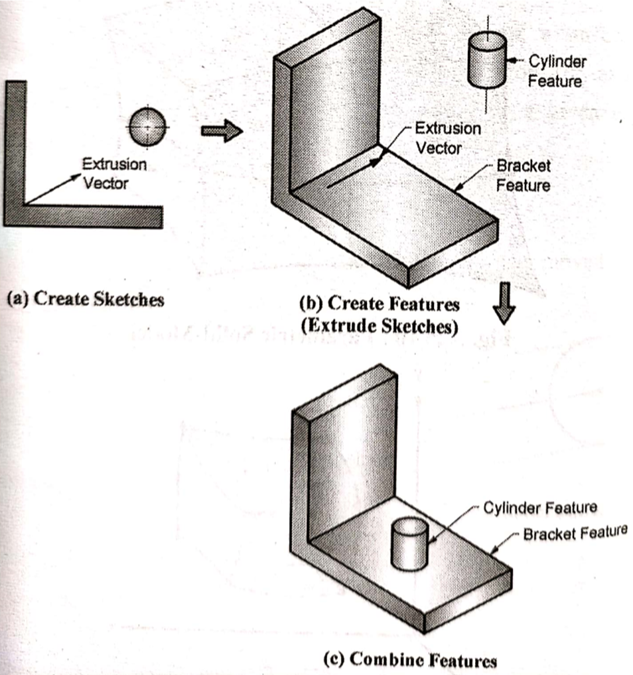
Most of the CAD softwares like Solidworks, CATIA, etc uses this approach to create a 3D model.
Q8) Explain 2 ½ extrusions and axisymmetric geometric models
A8)
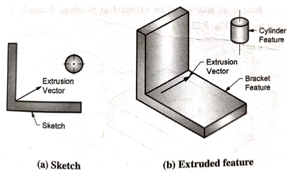
Extrude command is used to create 2 ½ extrusion models with a uniform thickness.
To create this type of models, a 2D sketch is required. This 2D sketch is the cross section of the desired model. Another input required to create this kind of model is a extrusion vector. The extrusion vector is always perpendicular to the plane of sketch. 2D sketch is extruded in a direction of extrusion vector, hence called as 2 ½ extrusions.
First step, we create the cross section in a sketch plane. Second, we extrude the cross section if the model has uniform thickness.
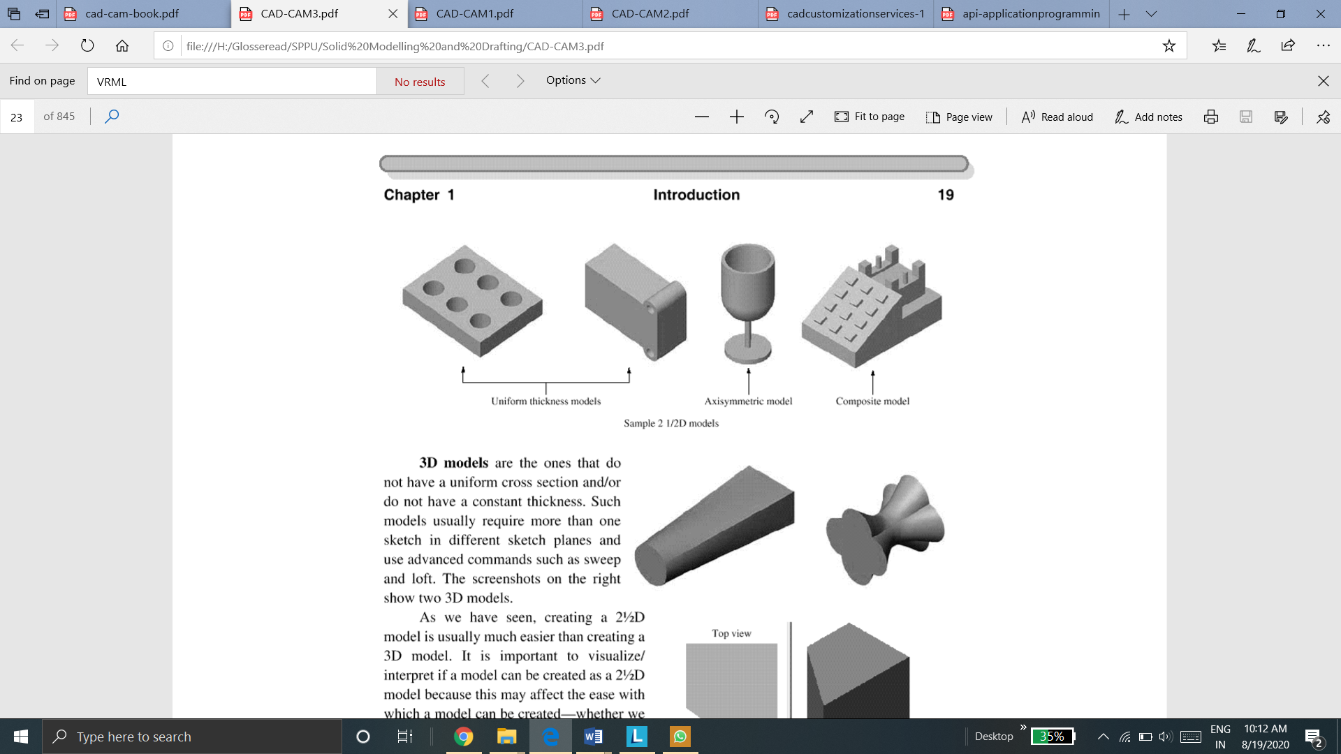
2 ½ D extrusion models
2. Axisymmetric models
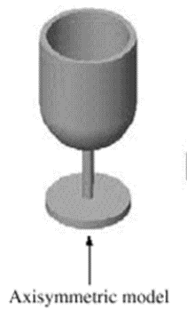
Axisymmetric models are the models which are symmetric about its axis.
These are also the type of 2 ½ D models.
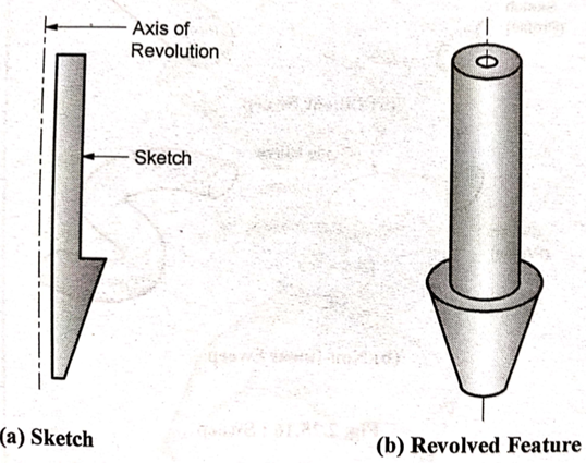
Revolve feature is used to create such kind of models. The input to create these models are a 2D sketch and axis of symmetry (revolution vector). Sketch and axis are in same plane. Sketch can be revolved for different angles to revolve. 360o revolve gives a full revolved sketch as shown below.
First, we create a sketch in the sketch plane with axis to revolve.
Second, we use revolve command and revolve the sketch about the axis for the required angle of revolution to create 2 ½ D axisymmetric model.
Q9) Give three types of geometric modelling
A9)
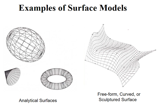
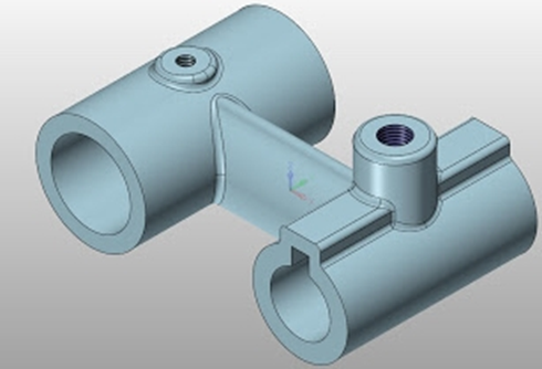
3D modeling is the process of developing graphics and images that appear to have three dimensions. It is of three types
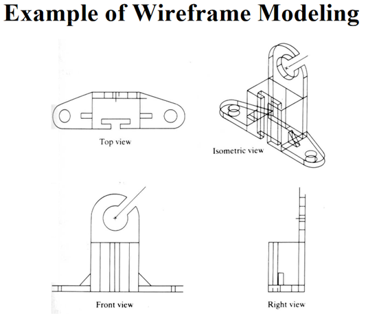
2. Surface Modelling
3. Solid Modelling
Q10) Write a note on VRML web-based viewing
A10)
VRML (Virtual Reality Modeling Language) enables us to display CAD models in a Web browser. Moreover, we can manipulate these models. For example, we can rotate a 3D view in the browser window to look at other invisible sides of it.
We need to use CAD system to generate a VRML file before we can use the VRML plug-in. While the CAD system is running, save the CAD file in VRML format to generate a VRML file. Simply click this sequence:
File – Save As—select the VRML filename. The VRML file extension is .wrl.
We need a browser window to open the .wrl file to view it. While the VRML file is open in the browser window, we manipulate it using the buttons offered by the plug-in.
VRML is a standard file format for three-dimensional graphics data, whereas CGM and DWF are two-dimensional formats. Although VRML has limitations, such as loss of accuracy and large file sizes, most geometric modeling system vendors have opted to go with the VRML output capability because of VRML's support for three-dimensional work. Some even go a step further, providing the ability to put the VRML model into a Web page and add information such as text and hyperlinks to the page. Just as in Hypertext Markup Language (HTML) hypertext links-now used to link to other World Wide Web (WWW or the Web) data VRML files contain URLs that can point to any other type of file on the Web, including other VRML files. When VRML files are read by a viewer, a navigable three-dimensional model appears. Hot spots (links to other URLs) are identified by a graphical change in the cursor, much like the user encounters on HTML pages [Beazley 1996]. Clicking the mouse on a hot spot loads the file associated with the hot spot. By clicking on the different parts of a model, for instance, a user can open a window that displays information written by another member of the design team. When clicking on a different corner of the image, the user can read technical characteristics about the model and can see concerns posted by someone else on the team.