Unit 3
Solid Modeling
Q1) Explain Geometry and Topology
A1) Geometry
Geometry is the actual dimension that defines the entities of the object.
The graphical information of dimension, length, angle, area and transformations is the geometry of the model. Geometry gives the dimensions and locations of the solid object in a chosen coordinate system.
Topology
Topology is the connectivity and associativity of the different entities of the object. It describes the way in which the different entities of the object are connected together.
Topology gives the invisible information about the connectivity, neighborhood, associatively, etc.
Following figure shows shame geometry but different topology
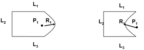
In the above figure, all geometric properties like lengths of line L1, L2 and L3, angle between these lines, radius of arc R1 and position of center of arc P1 are same in both figure. But due to different topology, both objects seem different. Similarly, there exists two models with same topology but different geometry.
It is important to note that, neither topology nor geometry alone can completely define a solid model. A model to fully define needs both geometrical and topological data.
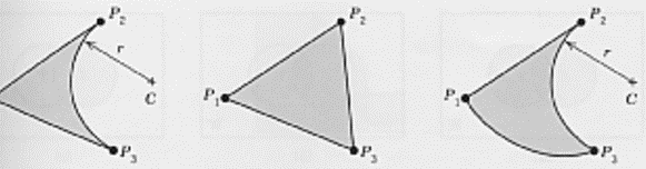
The above figure shows the different geometry with same topology.
Q2) Write a note on half spaces
A2) A half-space is that portion of an -dimensional space obtained by removing that part lying on one side of an -dimensional hyperplane.
In geometry, a half-space is either of the two parts into which a plane divides the three-dimensional Euclidean Space. More generally, a half-space is either of the two parts into which a hyperplane divides an affine space. That is, the points that are not incident to the hyperplane are partitioned into two convex sets (i.e., half-spaces), such that any subspace connecting a point in one set to a point in the other must intersect the hyperplane.
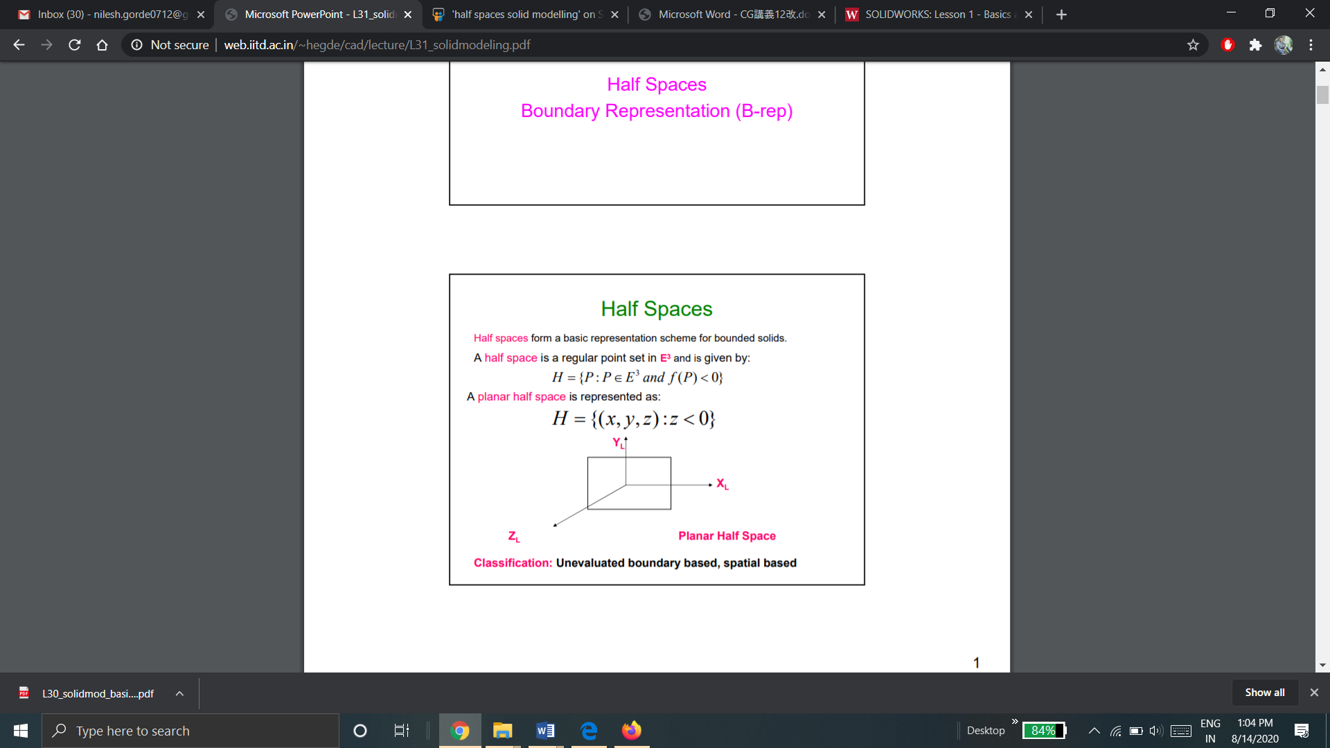
Half spaces form a basic representation scheme for bounded solids. A half space is a regular point set in E3 and is given by:
There are various types of half spaces:
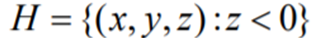
A planar half space is represented as:
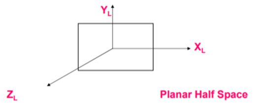
Planar half spaces are classified as Unevaluated boundary based, spatial based.
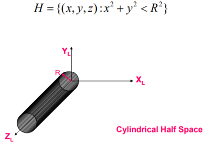
b. Cylindrical half space
A cylindrical Half Space is a given by:
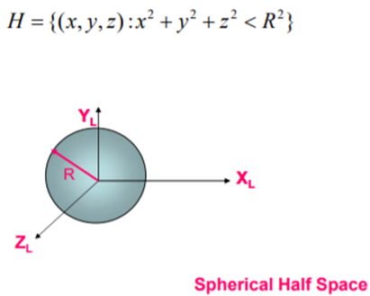
c. Spherical half Space
A spherical Half Space is a given by:
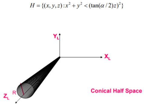
d. Conical Half Space
A conical Half Space is a given by:
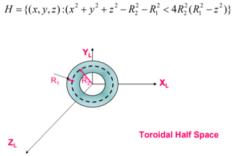
e. Toroidal half space
A toroidal Half Space is a given by:
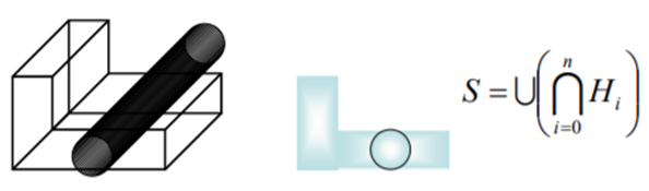
Construction of solid model from half spaces
By combining various half spaces, a solid model can be constructed. Complex objects can be modeled by combining Half Space using set operations.
Set operations are used to model a sold model from half spaces.
Advantages:
The main advantage is its conciseness of representation compared to other modeling schemes.
It is the lowest level representation available for modeling a solid object
Disadvantages:
The representation can lead to unbounded solid models as it depends on user manipulation of half spaces.
The modeling scheme is cumbersome for ordinary users / designers
Q3) Explain B-Rep solid modeling
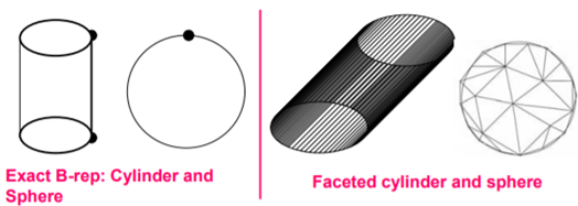
A3) Solid model is defined by their enclosing surfaces or boundaries. This technique consists of the geometric information about the faces, edges and vertices of an object with the topological data on how these are connected.
A solid is represented as a closed space in 3D space (surface connect without gaps). The boundary of a solid separates points inside from points outside solid.
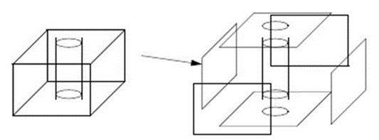
The B-rep is built on the idea that a physical object is enclosed by a set of faces, which themselves belong to closed and orientable surfaces.
A B-rep object is pictured below:
A boundary representation of a solid model consists of:
B-Rep can be represented by two schemes:
Q4) Explain the equation to check the validity of 3D object.
A4) The validity of a solid is checked through the mathematical evaluation called Euler’s Formula or Euler-Poincare Law. The Euler-Poincare law gives a quantitative relationship among faces, edges, vertices, faces’ inner loops, bodies or through holes (genus) in solids.
Euler’s equation is used to verify the topological validity of Boundary representation models. The B-rep model is topologically valid only if it satisfies Euler’s equation.
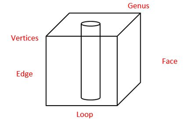
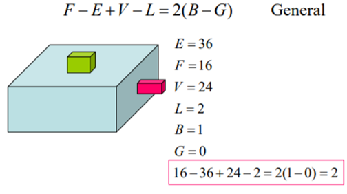
A general Euler’s equation of a 3D object is
F – E + V – L = 2(B – G)
Where,
F – number of holes in face,
E – number of edges,
V – number of vertices,
L – number of loops,
G – number of genus,
B – number of separate bodies.
Euler’s Equation for a simple 3D object (without internal void or hole, without through hole) is
F – E + V = 2
As for simple 3D object, L = 0, G = 0 and B = 1.
A general Euler’s Equation for a 2D object or open object is given as
F – E + V – L = B – G
A connected structure of vertices, edges and faces that always satisfies Euler’s formula is known as Euler object. The process that adds and deletes these boundary components is called an Euler operation.
Example:
Q5) Explain the Boolean operations used on CSG with example.
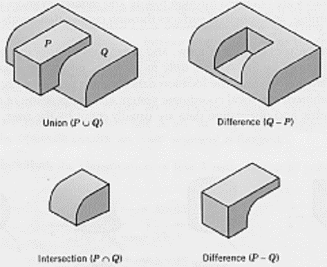
A5) Normal Boolean operations are union, intersection and subtraction which are given below
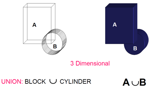
1) Union
The Boolean Operation “Union” represents the sum of all points in each of two defined sets - (logical “OR”). Also referred to as Add, Combine, Join, Merge
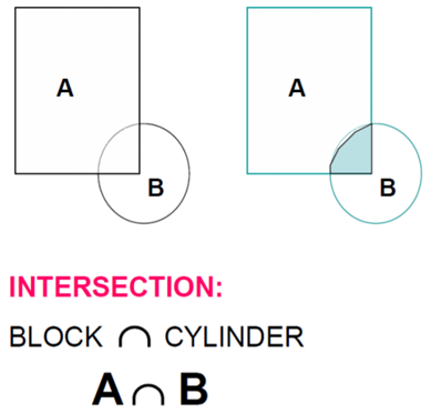
2) Intersection
The Intersection Operator refers tothose points common to each of two defined sets (logical “AND”)
In Intersection, set must share common volume. Intersection is also referred to as common, conjoin.
3) Difference
The Boolean Operator “Difference” represents the points in a source set minus the points common to a second set - (logical “NOT”). It is also referred to as subtraction, remove, cut.
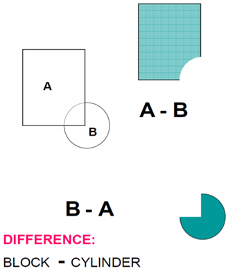
Examples of Boolean operations:
Q6) Write a note on data structure of CSG model.
A6) CSG representation is unevaluated – Faces, edges, vertices not defined in explicit. CSG model are always valid since they are built from solid elements. CSG models are complete and unambiguous.
In CSG, objects are represented as a combination of simpler solid objects or 3D geometric entities called as primitives.
A CSG model assumes that physical objects can be created by combining basic elementary shapes (primitives) through specific rules. A complete solid model is constructed by combining these “instances” using set specific, logic operations (Boolean Operators).
Data structure does not define model shape explicitly but rather implies the geometric shape through a procedural description – E.g: object is not defined as a set of edges & faces but by the instruction: union primitive1 with primitive 2.
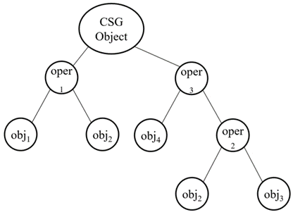
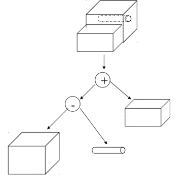
This procedural data is stored in a data structure referred to as a CSG tree. The data structure is simple and stores compact data which is easy to manage. CSG tree stores the history of applying Boolean operations on the primitives. In CSG data structure, data is stored in a binary tree format. The outer leaf nodes of tree represent the primitives. The interior nodes represent the Boolean operations performed.
Format of CSG tree is shown below.
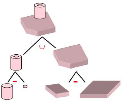
Few examples of solid model constructed in CSG are shown below with the help of CSG Tree.
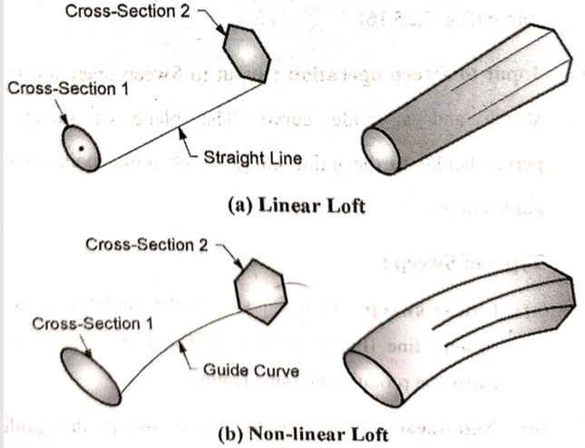
Q7) Give types of sweeps.
A7) There are three types of sweeps:
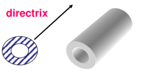
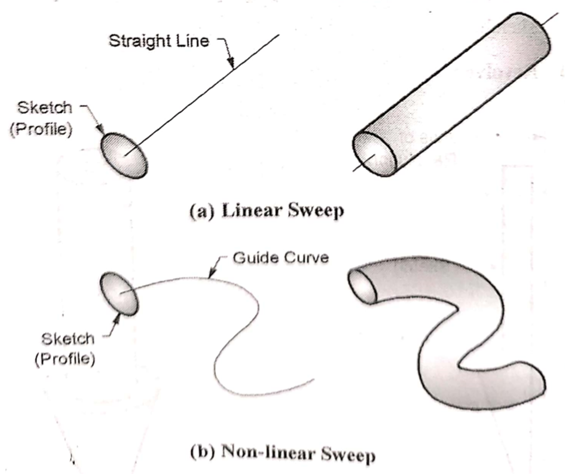
In a linear sweep, a surface or curve is moved in a linear or circular path.
Types of linear sweep are:
In transitional sweep, a surface or curve is moved by a given distance in space in a direction perpendicular to that plane of surface or curve. The translational sweep is also known as extrusion.
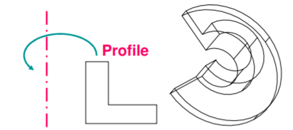
b. Rotational Sweep:
In rotational sweep, a surface or curve is rotated about an axis of rotation or axis of symmetry by a given angle.
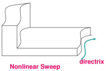
2. Non-linear sweep
In a non-linear sweep, a surface or curve is moved along a curved path.
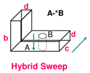
3. Hybrid Sweep
In a hybrid sweep, the two surfaces or curve are swept in two different directions and then resulting swept volume are guild together to form the object model.
Q8) Explain parametric modeling
A8) In parametric modeling the designer models a shape by using geometric constraints and dimension data on its elements. The geometric constraints describe the relation between the elements--for example, two faces are parallel, two edges lie in a plane, a curved edge is tangent to a neighboring straight edge, and so on. The dimension data include not only the dimensions assigned on the shape but also the relations between the dimensions. These relations are provided by the designer in the form of mathematical equations. Thus, parametric modeling constructs the required shape by solving the equations that express the geometric constraints, those derived from the dimensions, and those obtained from the dimensional relations. In parametric modeling, a shape is usually constructed in the following manner.
Note that the steps in parametric modeling modify a shape through the use of geometric constraints, dimensional data, and/or dimensional relations rather than by directly modifying the shape elements. Hence the designer can generate many design alternatives without considering the details of the shape's elements and concentrate on the functional aspects of the design. The two types of parametric modeling are based on the way they solve the equations that express the geometric constraints-those derived from the dimensions, and those obtained from the dimensional relations. One type solves the equations sequentially, whereas the other type solves them simultaneously. With the former, the shape varies, depending on the sequence in which the constraints are assigned. With the latter, the same shape is obtained regardless of the sequence of the constraints but it may be in trouble when conflicting constraints are assigned.
Q9) Define feature, shape and operation. Give different types of operations.
A9) Feature is defined as the combination of shape and operation to build the parts.
Shape is a 2D sketch.
Operation is an activity that converts the sketch into a 3D shape.
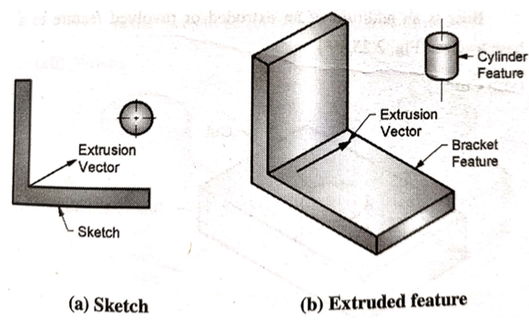
Examples of feature operation are:
Extrude feature is used to create 2 ½ extrusion models with a uniform thickness.
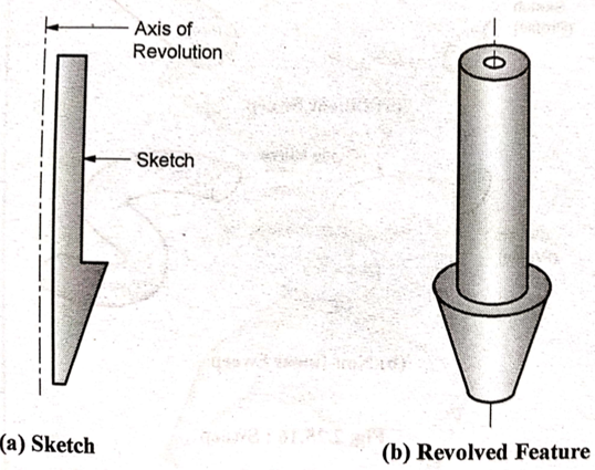
b. Revolve
Revolve feature is used to create axisymmetric objects
c. Sweep
Sweep feature sweeps a sketch or cross section along a guide curve.
d. Loft
Loft blends multiple cross section along a guide curve to create a solid.
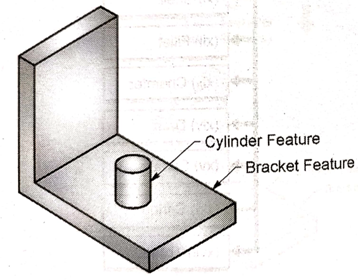
e. Boss
Boss is an addition of an extruded or revolved feature to a base feature
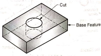
f. Cut
Cut is the subtraction of an extruded or revolved feature to a base feature.
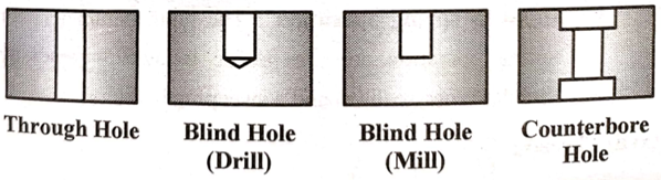
g. Hole
Hole is the subtraction of a cylinder from a solid or a base feature.
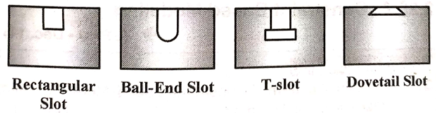
h. Slot
Slot is the subtraction of the extruded feature from a solid or a base feature.
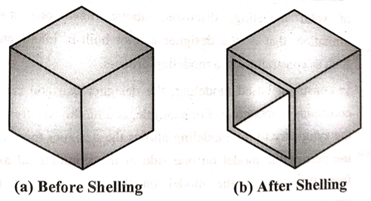
i. Shell
Shell feature is used to create a thin walled hollow solid.
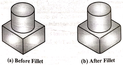
j. Fillet
Fillet is used to round off or smoothen the sharp corners and edges of the solids
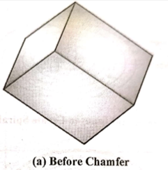
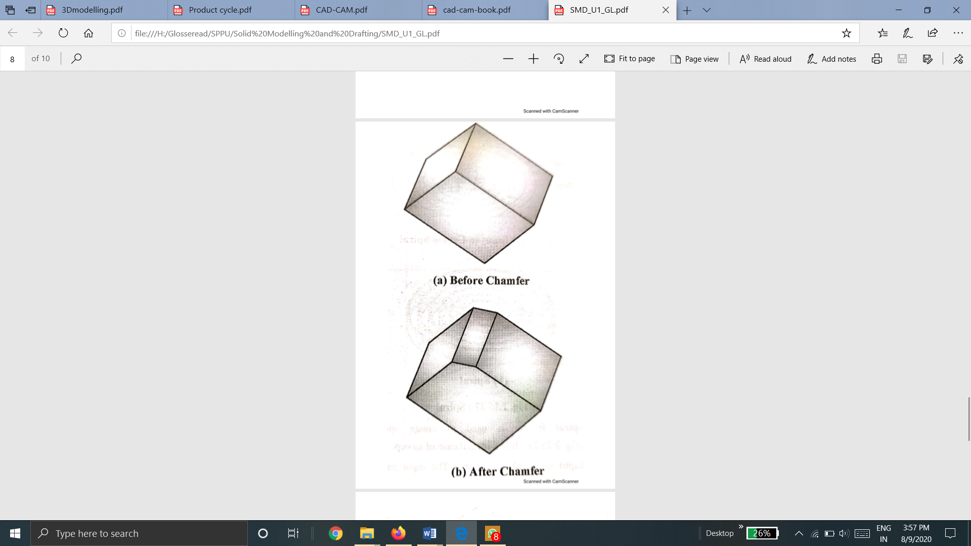
k. Chamfer
Chamfer feature is used to remove sharp edges and corners from the solid by creating beveled edges.
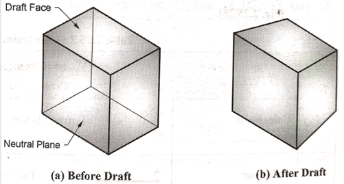
l. Draft
Draft feature is used to create taper on the surface of the object.
Q10) Explain Bottom-up and top-down approaches in assembly modeling
A10) There are two approaches in assembly modeling
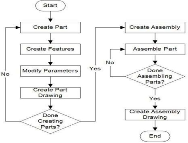
This is a logical, traditional, and most common approach. The individual parts are created independently, inserted into the assembly, and located and oriented (using the mating conditions) as required by the design. The first part inserted is known as the base and is fixed.
The individual parts are created independently, inserted into the assembly, and located and oriented (using the mating conditions) as required by the design.
The bottom-up-approach is the preferred technique if the parts have already been created (off the shelf).
It allows the designer to focus on the individual parts. It also makes it easier to maintain the relationships and regeneration behavior of parts than in the top-down approach.
Properties of bottom-up approach
Bottom-Up Approach
B. Top-Down Approach
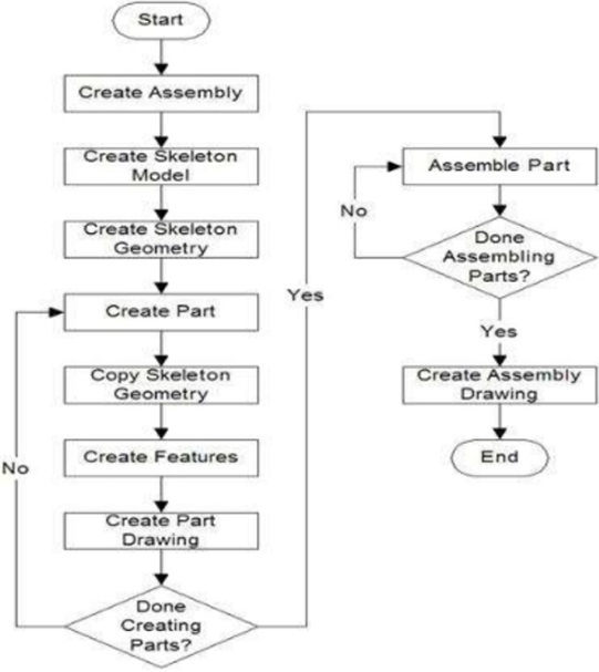
In this approach, the assembly file is created first with an assembly layout sketch. The parts are made in the assembly file or the concept drawing of the parts are inserted and finalized in the assembly file. In other words, the final geometry of the parts have not been defined before bringing them into the assembly file.
In this approach, the assembly file is created first with an assembly layout sketch.
The parts are made in the assembly file or the concept drawing of the parts are inserted and finalized in the assembly file. In other words, the final geometry of the parts have not been defined before bringing them into the assembly file. The approach is ideal for large assemblies.
Properties of Top-Down Approach
Top-Down Assembly Approach
Q11) What is design for manufacturing?
A11) DFM is the method of design for ease of manufacturing of the collection of parts that will form the product after assembly.
DFM is a tool used to select the most cost-effective material and process to be used in the production in the early stages of product design.
It is concerned with reducing overall part production cost. It helps to minimize complexity of manufacturing operations. It uses common datum features and primary axes. DFM seek to reduce material, overhead, and labor cost. DFM shorten the product development cycle time.
Principles of Design for Manufacturing
Q12) What is design for Assembly?
A12) DFA is the method of design of the product for ease of assembly.
DFA is a tool used to assist the design teams in the design of products that will transition to productions at a minimum cost, focusing on the number of parts, handling and ease of assembly.
It is concerned only with reducing product assembly cost. It helps to minimize number of assembly operations. individual parts in DFA tend to be more complex in design. DFA seek to reduce material, overhead, and labor cost.
DFA shorten the product development cycle time.
DFA is a process that REQUIRES involvement of Assembly Engineers.
Principles of Design for Assembly


