Unit 5
CAD Data Exchange
Q1) Explain the need of CAD data exchange.
A1) Need for CAD Data Exchange
Design projects requires data to be shared between suppliers and designers. Different companies often use different CAD systems. All CAD systems have their own database formats. So, in order to share these data, the CAD data must be exchanged from one format to another. These database formats are mostly proprietary and often confidential. For this reason, data conversion between systems becomes necessary. The exchange or conversion of CAD data from one format to another format is called as CAD data exchange.
For example, one organization can be developing a CAD model, while another performs analysis work on the same model; at the same time a third organization is responsible for manufacturing the product. The CAD systems currently available in market differ not only in their application aims, user interfaces and performance levels, but also in data structures and data formats therefore accuracy in the data exchange process is of paramount importance and robust exchange mechanisms are needed.
Other reasons for the need of CAD Data Exchange are:
Q2) What are CAD kernels. Explain GKS
A2) The kernel, also called a “geometric modeling kernel” or “solid modeling kernel” is the heart of a CAD system. The kernel is the code that determines how the image you see on the screen is actually described with math. This is important because describing manufacturable shapes in a mathematical representation involves making choices about how each shape is calculated and stored. A geometric modeling kernel is a 3D modeling component found in modeling software, such as computer-aided design (CAD). Without the kernel, it would not be possible to produce the images you see on the screen.
GKS (Graphical Kernel System) is an ANSI and ISO standard. GKS standardizes two-dimensional graphics functionality at a relatively low level. The primary purposes of the standard are:
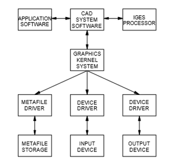
Figure shows the GKS implementation in a CAD workstation. The features of GKS include:
The drivers in GKS also include metafile drivers. Metafiles are devices with no graphic capability like a disc unit. The GKS always works in a rectangular window or world coordinate system. The window also defines a scaling factor used to map the created picture into the internal co-ordinate system of GKS called normalized device co-ordinates. Windows and view ports can then work in this co-ordinate system.
GKS offers two routines to define the user created pictures. They are primitive functions and attribute functions.
Q3) What are types of CAD data?
A3) Various Types of CAD data are:
Shape data: both geometric and topological information, part or form features. Fonts, color, annotation are considered part of the geometric information.
Non-shape data: graphics data such as shaded images, and model global data as measuring units of the database and the resolution of storing the database numerical values.
Design data: information that designers generate from geometric models for analysis purposes. Mass property and finite element mesh data belong to this type of data.
Manufacturing data: information as tooling, NC tool paths, tolerancing, process planning, tool design, and bill of materials (BOM).
Q4) Explain the concept of Data Interoperability
A4) Interoperability is the property that allows for the unrestricted sharing of resources between different systems. This can refer to the ability to share data between different components or machines, both via software and hardware, or it can be defined as the exchange of information and resources between different computers through local area networks (LANs) or wide area networks (WANs). Broadly speaking, interoperability is the ability of two or more components or systems to exchange information and to use the information that has been exchanged.
The definition of data interoperability is the ability of a system, software or product to exchange and make use of information with other systems, software or products without special effort on the part of the user. For two systems to be interoperable, they must be able to exchange data and subsequently present that data such that it can be understood by a user.
In other words, Data Interoperability is nothing but the exchange of data.
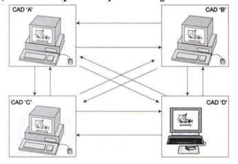
Data Interoperability
In order to exchange the data, the data format used by all the software should be same. However, the data formats are identified on the basis of modeling requirements and is therefore is not possible to have identical formats for all the system. However, it is possible to identify certain format for drawing exchange and make it standard so that various system can convert their internal format to this standard format or vice versa.
Q5) What are the challenges in CAD data conversion.
A5) Challenges in CAD data conversions / remedies
Q6) Explain the types of data conversion methods.
A6) There are three main methods of data conversion.
Direct data translators provide a direct solution which entails translating the data stored in a product database directly from one CAD system format to another, usually in one step. There usually exists a neutral database in a direct data translator. The structure of the neutral database must be general, governed by the minimum required definitions of any of the modelling data types, and be independent of any vendor format. Direct data translators are the tools used in the CAD system to directly convert the CAD data from one CAD system to another.
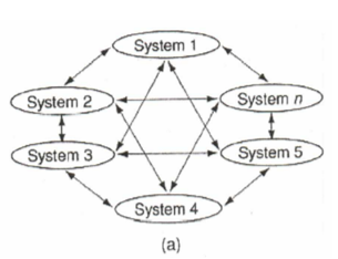
b. Neutral File Exchange
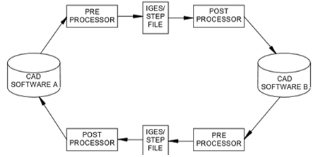
Neutral file exchange uses an intermediary neutral format to translate data between CAD systems. This method starts from a pre-processor embedded in the original CAD system, which generates the neutral file from the originating CAD format. The target CAD system post-processes the neutral file and converts it into the target native format. Some neutral formats are defined by standards organizations such as IGES and STEP while others are proprietary but still widely used and are regarded as quasi industry standards.
These neutral files will have standard formats and software packages can have pre-processors to convert drawing data to neutral file and postprocessors to convert neutral file data to drawing file. Figure illustrates how the CAD data transfer is a accomplished using neutral file.
c. Third-party Translation
Several companies specialize in CAD data translation software that can read from one CAD system and write the information in another CAD system format. There are a handful of companies that provide low-level software toolkits to directly read and write the major CAD file formats. Most CAD developers license these toolkits, to add import and export capabilities to their products. There are also a significant number of companies that use the low-level translation toolkits as the basis for building standalone end-user translation and validation applications. These systems have their own proprietary intermediate format some of which will allow reviewing the data during translation. Some of these translators work stand-alone while others require one or both of the CAD packages installed on the translation machine as they use code (APIs) from these systems to read/write the data. Some companies also use these low-level toolkits to create import or export plug-ins for other CAD applications.
Q7) Write a note on DXF neutral file.
A7) Drawing Exchange Format DXF format has been developed and supported by Autodesk for use with the AutoCAD drawing files. It is not an industry standard developed by any standards organization, but in view of the widespread use of AutoCAD made it a default standard for use of a variety of CAD/CAM vendors.
A drawing Interchange File is simply an ASCII text file extension of .dxf and specially formatted text. The overall organization of a DXf file is as follows:
HEADER Section
This section contains general information about drawing similar to the Global section of IGES. It consists of the AutoCAD database version number of system variables. Each parameter contains a variable name and associated value. This information is used for database conversion purpose.
CLASSES Section
It holds the information for application-defined classes, whose instances appear in the BLOCKS, ENTITIES and OBJECTS sections of the database. A class definition is permanently fixed in the class hierarchy.
TABLES Section
This contains definitions for the following symbol tables which directly relates to the object types available in AutoCAD.
BLOCKS Section
This contains block (symbol) definition and drawing entities that make up each block reference in the drawing.
ENTITIES Section
This contains the graphical objects (entities) in the drawing, including block references (insert entities).
OBJECTS Section
This contains the non-graphical objects in the drawing. All objects that are not entities or symbol table records are stored in this section. Examples of entries in the OBJECTS section are dictionaries that contain mline (multiple lines) styles and groups.
TERMINATE Section
It indicates the end of the file.
Q8) Explain the structure of IGES file format.
A8) An IGES file is composed of six sections in the following order. A record is a line comprising 80 characters.
Flag Section
This is optional and is used to indicate the form in which the data is specified. Originally, the initial versions contained the data in ASCII format with a very detailed structure. This has been criticized by a number of people in view of the very large file sizes. From version 3.0 onwards, the format has been standardized in the following three modes.
The other two options provided help in reducing the bulk of the drawing exchange file size.
The sequence number has a starting character signifying the sub-section.
They are
S for Start Section
G for Global section
D for Directory entry section
P for Parameter Entry section
T for Terminate section
Start Section
This section contains a man-readable prologue to the file. The information contained in this section is essentially for the person who would be postprocessing this for any other application. Any number of lines can be contained in this section.
A simple listing of IGES file for the drawing is shown in fig below
Global Section
This contains information about details of the product, the person originating the product, name of the company originating it, date, the details of the system which generated it, drafting standard used and some information required for its postprocessing on the host computer.
Directory Entry Section
For each entity present in the drawing is fixed in size and contains 20 fields of 8 characters each. The purpose of this section is to provide an index for the file and contain attribute information. Some of the attribute information such as colour, line type, transformation matrix, etc., may be present directly or through a pointer (to a record in the same file) where the necessary information is stored. It also contains the pointer to the parameter data section entry which actually contains the requisite parameter data.
Parameter Data Section
This data section is associated with the entities. A free format is allowed for maximum convenience. It may contain any number of records.
Terminate Section
The terminate section contains a single record that specifies the number of records in each four preceding sections for checking purpose.
Q9) What are the limitations of DXF and IGES files.
A9) Limitation of IGES and DXF files
The IGES and DXF files were developed to exchange product data definition data instead of product data. By product data we mean the data relevant to the entire life cycle of the product.
Even though the specification of the IGES and the DXF file has been broadened to encompass some of these product data, the data carried by those files are inherently inefficient to be the product data supporting the entire life cycle.
Q10) Explain the architecture of STEP file.
A9) STEP architecture has four main components:
Q11) Write a note on Parasolid.
A11) Most high-end CAD/CAM systems have their proprietary geometric modeler embedded within the modeling application. Parasolid is a portable “kernel” that can be used in multiple systems - both high-end and mid-range. By adopting Parasolid, start-up software companies have eliminated a major barrier to application development - a high initial investment. This enabled them to effectively market softwares with strong solid modeling functionality at lower-cost.
Parasolid’s modeling abilities include:
In a nutshell, Parasolid incorporates object-oriented routines needed to create real life, complex models great accuracy, reliability and speed. Some of the functionalities in Parasolid are:
Q12) Write a note on Data Quality.
A12) Data quality can be addressed intrinsically and extrinsically. Intrinsic problems are those related to the CAD model’s structure before any translation process begins, while extrinsic problems relate to those issues appearing during translation. The development of STEP is the best solution to solve the extrinsic problems, extending its current capabilities to support 2-D parametric sections, 3-D parametric assemblies, and history-based modeling. Product data quality is a key issue to avoid intrinsic data exchange problems and simplify the integration of downstream applications in the design chain.
Throughout the product manufacturing lifecycle, specialized software exists for specific fields, creating a need to ensure one has “the right software in the right place.” It is without a doubt that many software solution providers have stood up to challenge this status quo, which has not been easy.
In CAD data exchange, accuracy and consistency of the data plays an important role.
Accuracy: Accuracy of CAD data means how accurately the CAD data is converted from one CAD system to another.
Consistency: Consistency of a CAD data transfer means, same quality of data should be converted in every CAD data interoperability.
Q13) What are the requirements for CAD file formats for subtractive and additive manufacturing systems.
A13) Requirements of CAD file for 3D printing (Additive Manufacturing):
Three-Dimensional Printing (3DP) technology was developed at the MIT and licensed to several corporations. It is a powder based rapid prototyping process.
The three main requirements of CAD file formats for 3D printing system or any other additive manufacturing based system like Fused Deposition modelling (FDM), Selective Laser Sintering (SLS), Stereolithography (SLA), Laminated object Manufacturing (LOM), etc. are:
Lot of people choose STL file format for 3D printing.
The most important consideration to consider here is the resolution of your model. If you try to export an STL with a low resolution, your model will look faceted and if you export an STL with too high of a resolution, your model will become very large and difficult to share. AMF(additive manufacturing file format) is the file format developed of additive manufacturing systems.
Requirements of CAD file format for subtractive manufacturing:
Computer Aided Manufacturing (CAM) is the use of software and computer-controlled machinery to automate a manufacturing process.
Examples of subtractive manufacturing in CAM are NC, CNC machine tools.
In order to manufacture a component directly form CAD data, the most commonly required CAD file format is DXF/DWG file format.
Other file formats supported are: IGES, STEP, etc.