Unit - 4
Fluid Dynamics
Q1) Explain the forces acting on fluid mass in motion with the help of diagram.
A1) The motion of the fluid element is influenced by the following forces
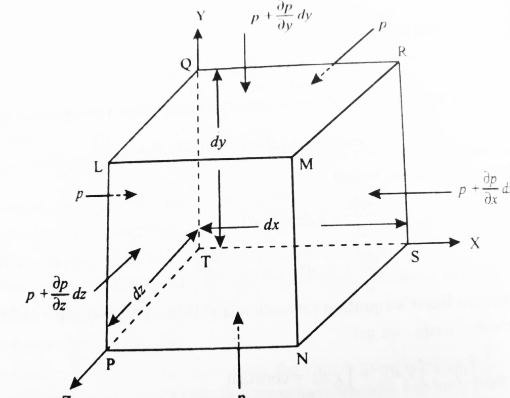
The net pressure force in X direction = p dy dz – 
= 
2. Gravity or body force
Let B be the body force per unit mass of fluid having components Bx, By & Bz
In x, y & z directions respectively.
Then, body force acting on the parallelepiped in the direction of X coordinate is = Bx dx dydz
3. Inertia force
The inertia force acting on the fluid mass, along the X coordinates is given by,
Mass x acceleration =  dx dydz
Q2) State the Euler’s equation of motion along a streamline and its integration
A2) Consider steady flow of an ideal fluid along the shown tube.
Separate out a small element of fluid of cross- sectional area dA and length ds from stream tube as a free body from the during fluid.
Fig. shows such a small elements LM of fluid of cross Section area dA and length ds.
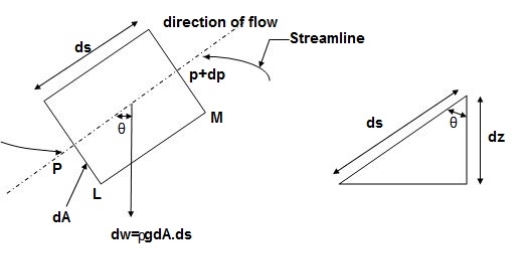
Let, p= Pressure of the elements at L
p + dp = Pressure on the element at M, and
V=Velocity of the fluid element.
The external forces tending to accelerate the fluid elements in the direction of streamline are as follows:
= - .g.dA.ds.cos
=- .g.dA.ds (dz /ds) (Cos
 = dz/ds)
= - .g.dA.dz
Mass flow of the fluid element =  .dA.ds
The Acceleration of the fluid element
a = dv/dt = dv/ds * ds/dt = v. dv/ds
Now, according to Newton’s second law of motion, force= mass x acceleration.
:. – dp. dA - .g.dA.dz=
  .dA.ds x v.dv/ds
Dividing both sides by  .dA, we get
-dp/ - g.dz= v.dv
Or dp/ + v.dv + g.dz=0
This is the required Euler’s equation for motion.
Integrating the Euler’s equation of motion, we get
1/
p/ + v2 /2 + gz = constant
dividing by g, we get
p/ g + v2/2g + z = constant
p/w + v2/2g + z = constant
or in other words,  +
+
which proves Bernoulli’s equation.
Q3) What are the assumptions of Bernoulli’s equation?
A3) Assumptions made in Bernoulli’s equation.
Only forces acting on the fluid are the gravity forces & pressure forces
Q4) What is the Modified Bernoulli’s equation, its applications and limitations?
A4) Modified Bernoulli’s equation, its applications and limitations
 +
+ + hL
+ hL
 hL = Loss of energy between section 1 & 2.
Applications of Bernoulli’s equation
Bernoulli’s equation is applied is all problems of incompressible fluid flow where energy considerations are involved, but we shall consider its applications to the following measuring devices:
i) Venturimeter
ii) Pitot- tube
iii) Sub-merged orifice
iv) Orifice meters
v) Rotameter.
Limitation of Bernoulli’s equation
Q5) Explain the concept of Hydraulic grade line and total energy line.
A5) Hydraulic grade line and total energy line
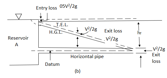
The concept of hydraulic gradient line and total energy line is quite useful in the study of flow of fluid in pipes.
Total energy Line (T.E.L. or E.G.L)
Total head = 
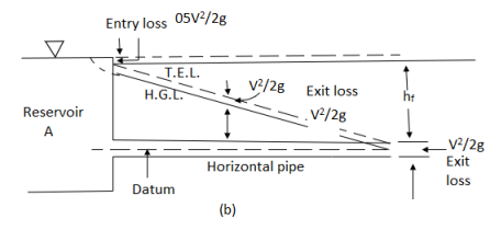
Hydraulic gradient Line (H.G.L)


Q6) Define the Linear momentum equation and kinetic energy correction factor, momentum correction.
A6) Linear momentum equation
F = m x a
Where a is the acceleration acting in the same direction as force F
But a = 
F = m x 
=  m is constant can be taken inside the differential
Above equation is known as the momentum principle.
It can be written as F dt = d(mv)
Which is known as the momentum equation & states that the impulse of force F acting on a fluid of mass m in a short interval of time dt is equal to the change of momentum d(mv) in the direction of force.
Kinetic Energy Correction Factor
Kinetic energy correction factor is defined as the ratio of the kinetic energy of flow per second based on actual velocity across the section to kinetic energy of flow per second based on average velocity across the same section. It is denoted by  .
.
 =
= 
 = 1 for uniform velocity distribution
 = 1.02 to 1.15 for turbulent flows.
 = 2 for laminar flow.
Momentum Correction Factor
Momentum correction factor is defined as the ratio of momentum of the flow per second based on actual velocity to the momentum of the flow per second based on average velocity across a section. It is denoted by  .
.
 =
= 
 = 1 for uniform flow
 = 1.01 to 1.07 for turbulent flow in pipes
 = 4/3 = 1.33 for laminar flow in pipes.
Q7) Explain Venturimeter with the help of diagram.
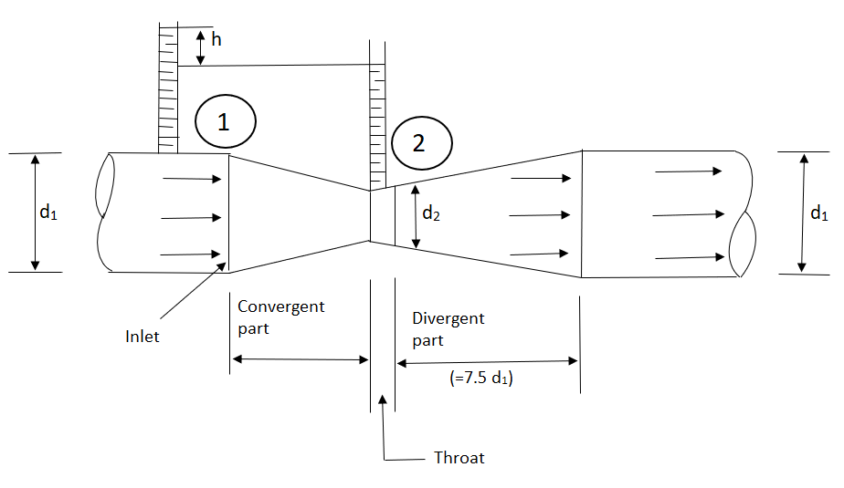
A7) A venturimeter is a device used for measuring the rate of a flow of a fluid flowing through a pipe it consists of three parts:
i) A short converging part, ii) Throat, and (iii)Diverging Part
It is based on the principle of Bernoulli’s equation.
Expression for Rate of flow through venturimeter
Consider a venturimeter fitted in a horizontal pipe through which a fluid is following as shown in fig.
Let d1 = diameter at inlet or at section (1)
P1= pressure at section (1)
V1 = velocity of fluid at section (1)
a1= area of section (1) =π/4. d2
and d2, P2, V2, a2 are corresponding values at section (2)
Applying Bernoulli’s equation at section (1) and (2) we get
 +
+
As pipe is horizontal hence z1 = z2


But  is the difference of pressure heads at section land 2 and it is equal to h
 =h
=h
Substituting this value of  in the above eqn we get.
 h =
h =  ………… (1)
Now applying continuity equation at section 1 and 2
a1 v1 = a2 v2
 v1 =
v1 = 
Substituting this value of v1 in equation 1


 =
= 
Q = a2v2
=a2 
= 
Above equation gives the discharge under ideal conditions and is called, theoretical discharge Actual discharge will be less than theoretical discharge.
Qact =
Where Cd = co-efficient of venturimeter and its value is less than 1.
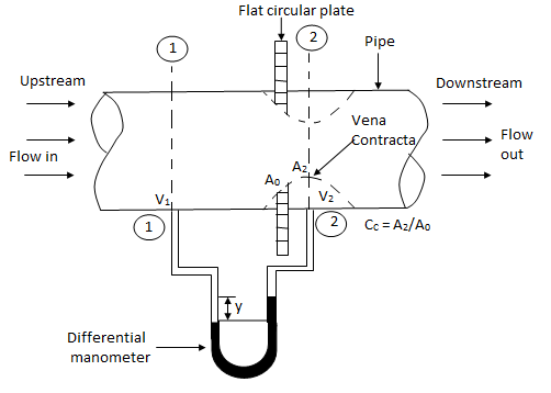
Q8) Explain Orifice meter with the help of diagram?
A8) Orifice meter
Orifice Meters or Orifice plate.
Q9) Explain Rotameter in detail.
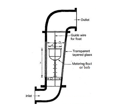
A9) Rotameter
Construction-
Working-
The discharge through a rotameter is given by:

Q = Volume flow rate
Cd = coefficient of discharge.
Aann = Annular area between float and tube
Vfl = Volume of float.
 fl = Density of float material
 f = Density of fluid, and
Af = Maximum cross-sectional area of the fluid.
As the flow area Aann is a function of height of float in the tube, the flow rate scale can be engraved on the tube corresponding to a particular float.
Q10) What are the advantages and limitations of Rotameter?
A10) Advantages
1) Simpler in operating.
2) Handling and installation is easy.
3) Wide variety of corrosive fluids can be handled.
4) Low cost.
Limitations
1) Mounted vertically, limited to small pipe sizes and capacities.
2) Less accurate compared to Venturimeter and orifice meter
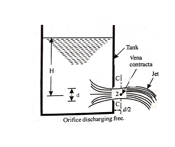
Q11) Explain the concept of Flow through sharp edged circular orifice discharging free.
A11) Flow through sharp edged circular orifice discharging free
An orifice is an opening in the wall or base of a vessel through which the fluid flows. The top edge of the orifice is always below the free surface.
Flow through an orifice
Considering points 1 and 2 as shown in figure and applying Bernoulli’s theorem, we have


Further, if the cross-sectional area of the tank is very large, the liquid at point 1 is practically standstill and hence V1 = 0


Q12) Explain the Hydraulic coefficients for Orifice?
A12) Hydraulic coefficients for orifice
Coefficient of Contraction (Cc)
The ratio of area of the jet at vena contracta to the area of the orifice is known as coefficient of contraction. It is denoted by Cc.
ac= Area of jet at vena contracta, and
a = Area of orifice
Cc = ac/a
The value of Cc varies from 0.613 to 0.69.
Coefficient of velocity (Cv)
The ratio of actual velocity (v) of the jet at vena contracta to the theoretical velocity (Vth)is known as coefficient of velocity.
It is denoted by Cv.


where, V = Actual velocity
H = Head under which the fluid flows out of the orifice.
The value of Cv varies from 0.95 to 0.99.
Coefficient of Discharge (Cd)
The ratio of actual discharge (Q) through an orifice to the theoretical discharge (Qth) is known as coefficient of discharge.
It is denoted by Cd.


The value of Cd varies from 0.62 to 0.65
Coefficient of Resistance (Cr)
The ratio of loss of head in the orifice to the head of water available at the exit of the orifice is known as coefficient of resistance.
It is denoted by Cr.

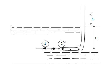
Q13) Explain the device Pitot-tube.
A13) Pitot-tube
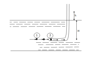
P1= intensity of pressure at point (1)
V1 = velocity of flow at (1)
P2 = pressure at point (2)
V2 = velocity at point (2), which is zero
H = depth of tube in the liquid.
h = rise of liquid in the tube above the fire Surface
Applying Bernoulli’s equation at points (1) and (2)
We get
 +
+
But Z1 = Z2 as points (1) and (2) are the same line and V2 =0
 = pressure Lead at (1) = H
 = pressure head at (2) = (h+H)
Substituting these values, we get
H+  = (h+H)
:. h=  or V1 =
This is theoretical velocity.
Actual velocity is gives by (V1)act= Cv
Where Cv= Co-efficient of pitot-tube
:. Velocity at any point V= Cv
Q14) Explain Linear Momentum Equation using differential approach.
A14) Linear Momentum Equation using differential approach

Where,
 = mass density of the fluid
u, v & w= Components of velocity of flow entering the three faces of the parallelepiped
Q15) State the Navier – Stocks equation.
A15) Introduction to Navier – Stocks Equations
Bx – - v [
- v [ +
+
By –  - v [
- v [ +
+
Bz –  - v [
- v [ +
+
Where,
B be the body force per unit mass of fluid having components Bx, By & Bz in X, Y, Z direction s respectively
 = mass density of the fluid
u, v & w= Components of velocity of flow entering the three faces of the parallelepiped
v= kinematic viscosity
Q16) An oil of sp.gr 0.8 is flowing through a venturimeter having inlet diameter 20 cm & throat diameter 10cm. The oil mercury differential nanometers show a reading 25 cm. Calculate the discharge of oil through the horizontal venturimeter. Take cd = 0.98
A16) Given
S1= 0.8
Sm =13.6
d1=0.2m
d2=0.1m
x=0.25m
cd=0.98
A1 = π/4*d12 = π/4*0.22 = 0.0314 m2
A2 = π/4*d22= π/4* 0.12 = 7.85*10-3m2
 = 4m
= 4m
Q = 
= 
=0.0705 m3/sec
Q17) The inlet & throat diameters of horizontal venturimeter are 30cm & 10cm respectively. The liquid flowing throat the meter is water, the pressure intensity at inlet is 13.734 N/cm2 while the vacuum pressure head at the throat is 37cm of mercury. Find rate of flow Assume that 4%of the differential head is lost between the inlet & throat. Find also the value Cd for the venturimeter.
A17) Given
d1 =0.3m
d2= 0.1m
p1=13.734 x10⁴N/m2
Vacuum pressure head = - 0.37m of Hg
hf = 4 % of h = 0.04h
A1= x d12 =
 =0.0706m2
A2=  x d22=
 =
=
P2 = w *Vacuum pressure head
= (13.6 x 9810) x -0.37
= - 49.37 x10³ N/m2
h=  =
=
= 19.03 m
hf= 0.04h = 0.04 x 19.032 = 0.7613m
Cd =  =
= = 0.98
Q=
= 
= 0.149 m3/sec
Q18) A 30cm x 15cm venturimeter is provided a vertical pipe line carrying oil of specific gravity 0.9, The flow being upwards. The different in elevation of the venturimeter is 30cm. The differential U tube mercury manometer shows a gauge deflection of 25cm calculate i) the discharge ii) pressure difference between the entrance section throat section. Take Cd = 0.98
A18) Given
d1 = 0.3m
d2 = 0.15m
SL =0.9
Z1=0
Z2 = 0.3 M
X = 0.25 M
A1 = π/4 * d12 = π/4*0.32 = 0.0706m2
A2 = π/4 * d22 = π/4*0.152 = 0.0176m2
h= - 1) = 0.25 (
Q =
= 
=0.149 m3/sec
h=  +(z1-z2)
3.53 =  +(0 - 0.3)
P1-P2 =33.81 x 10³ N/m2
Q19) Find the discharge of water flowing through a pipe 30cm diameter placed in on inclined position where a venturimeter is inserted, having a throat diameter of 15 cm. The difference of pressure between the main & throat is measured by a sp.gr 0.6 in an inverted tube which gives a reading of 30 cm. The loss of head between the main & threat 0.2 times the kinetic head of the pipe.
A19) Given
d1 = 0.3 m
d2 = 0.15m
Sm = 0.6
x= 0.3m
hL=0.2 
A1 =  * d12 =
  * 0.32 = 0.0706m2
A2 =  *d22 =
  * 0.152 = 0.0176 m2
h = x [1-  ] = 0.3 [1-
  ] = 0.12m
Applying Bernoulli’s eqn. at section 1& 2
:.  +
+  + Z1 =
 +
+ + Z2+ hL
( -
-  ) + (Z1-Z2) =
 -
-  + hL
+ hL
Applying Continuity eqn. at section (1) & (2)
A1V1 =A1 V2
 = V2
= V2
 = V2
= V2
:. V2 = 4V1
:. ( -
-  ) + (Z1-Z2) =
 -
-  +
+ 
:. h = 
:. 0.12 = 
:.V1 = 0.393m/s
:.Q = A1 V1
= 0.0706 x 0.393
= 0.0277 m3/sec
Q20) State and explain Applications of Bernoulli’s equation.
A20) Applications of Bernoulli’s equation
Bernoulli’s equation is applied is all problems of incompressible fluid flow where energy considerations are involved, But we shall consider its applications to the following measuring devices:
i) Venturimeter
ii) Pitot- tube
iii) Sub-merged orifice
iv) Orifice meters
v) V Notch
i) Venturimeter
A venturimeter is a device used for measuring the rate of a flow of a fluid flowing through a pipe it consists of three parts:
i) A short converging part, ii) Throat, and (iii)Diverging Part
It is based on the principle of Bernoulli’s equation.
Expression for Rate of flow through venturimeter
Consider a venturimeter fitted in a horizontal pipe through which a fluid is following as shown in fig.
Let d1 = diameter at inlet or at section (1)
P1= pressure at section (1)
V1 = velocity of fluid at section (1)
a1= area of section (1) =π/4. d2
and d2, P2, V2, a2 are corresponding values at section (2)
Applying Bernoulli’s equation at section (1) and (2) we get
 +
+
As pipe is horizontal hence z1 = z2


But  is the difference of pressure heads at section land 2 and it is equal to h
 =h
=h
Substituting this value of  in the above eqn we get.
 h =
h =  …………. (1)
Now applying continuity equation at section 1 and 2
a1 v1 = a2 v2
 v1 =
v1 = 
Substituting this value of v1 in equation 1


 =
= 
Q = a2v2
=a2 
= 
Above equation gives the discharge under ideal conditions and is called, theoretical discharge Actual discharge will be less than theoretical discharge.
Qact =
Where Cd = co-efficient of venturimeter and its value is less than 1.
ii) Pitot-tube:
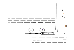
P1= intensity of pressure at point (1)
V1 = velocity of flow at (1)
P2 = pressure at point (2)
V2 = velocity at point (2), which is zero
H = depth of tube in the liquid.
h = rise of liquid in the tube above the fire Surface
Applying Bernoulli’s equation at points (1) and (2)
We get
 +
+
But Z1 = Z2 as points (1) and (2) are an the same line and V2 =0
 = pressure Lead at (1) = H
 = pressure head at (2) = (h+H)
Substituting these values, we get
H+  = (h+H)
:. h=  or V1 =
This is theoretical velocity.
Actual velocity is gives by (V1)act= Cv
Where Cv= Co-efficient of pitot-tube
:. Velocity at any point V= Cv
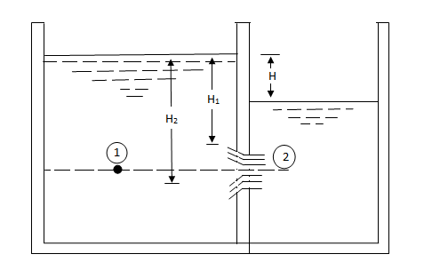
iii) Fully sub merged orifice

H1 = Height of water above the top of the orifice on the upstream side,
H2 = Height of water above the top of the orifice on the downstream side,
H = Difference in water level.
b = Width of orifice,
Cd = Co-efficient of discharge.
Height of water above the center of the orifice on the upstream side,
= 
Height of water above the center of the orifice on the downstream side,
= 
Applying Bernoulli’s eqn at 1 & 2


 V1 is negligible.


V2 = 
Area of orifice = b ( H2 – H1)
Q = Cd x b ( H2 – H1) x 
iv) Orifice Meters or orifice plate.

v) V notch
Let H = head of water over apex above the notch
 = Angle of notch
Cd= Co-efficient of discharge.
Consider a horizontal strip of water of thickness dh at depth h from water surface as shown in fig.
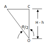

AC = H – h
Width of strip = AB = 2AC = 2H – h 
Area of strip = 2 ( H – h) 
Theoretical velocity of water through strip = 
Discharge through strip dQ = Cd x Area of strip x Velocity
= Cdx 2 (H – h)  x
x 
= 2 Cdx (H – h)  x
x 
Total discharge Q = 
= 
= 
= 
= 
= 

