Unit 5
Internal & External Flow
Q1) Define Renolds number.
A1) Reynolds Numbers (Re)
It is defined as the ratio of the inertia force to the viscous force.
Re =  =
= 
Re = 
For pipe flow Re = 
Q2) Explain the concept of entrance region and fully developed flow with the help of diagram?
A2)
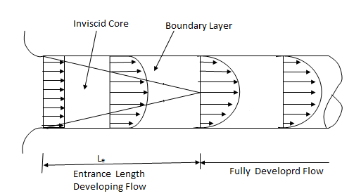
Q3) Explain the flow of viscous fluid in circular pipes.
A3) Flow of viscous fluid in circular Pipes – Hagen Poiseuille Law
(Velocity & shear stress distribution for laminar flow in pipe)
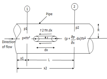
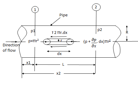
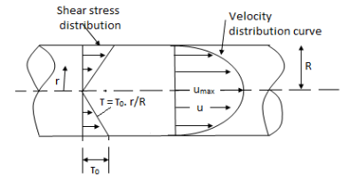
Fig: Shows a horizontal circular pipe of radius R, having laminar flow of fluid through it.
Consider a small concentric cylinder of radius r and length dx as a free body.
If  is the shear stress, the shear force F is given by
F =  x 2
x 2  r x dx
Let P be the intensity of pressure at left end and the intensity of pressure at the right end be (
Thus, the force acting on the fluid element are:
i) the shear force,  x 2
x 2 r x dx on the surface of fluid element.
ii) The pressure force, P x  on the left end.
iii) The pressure force, ( on the right end.
For steady flow, the net force on the cylinder must be zero.
 [ p x
[ p x  - (
- ( ] –
] – 
 -
-  -
-

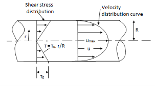
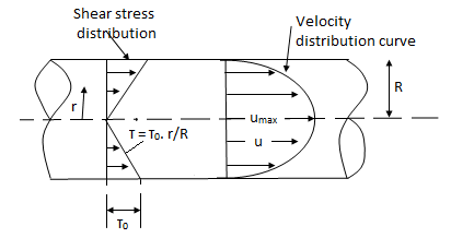
Shear stress is zero at the centre of pipe (r = 0) and maximum at the pipe wall given by
 (
( )
)
From Newton’s Law of viscosity.

In this equation, the distance y is measured from the boundary. The radial distance r is related to distance y by the relation.
y = R-r ordy = -dr

Comparing two values of 
 =
= 
 du =
du =  (
( )r.dr
)r.dr
Integrating the above equation w. r. t. ‘r’ we get
 u =
u =  .
.  r2 + C --------------- (ii)
Where C is the constant of integration and its value is obtained from the boundary conditions.
At r = R, u = 0
 0 =
0 =  .
.  R2 + Cor C =
  .
.  R2
R2
Substituting this value of C in eqn. (ii) we get,
 u =
u =  .
.  r2
r2 .
.  R2
R2
 u = -
u = -  .
.  (R2 – r2)
Shows that velocity distribution curve is a parabola.
The maximum velocity occurs, at the centre and is given by.
 umax = -
  R2
R2
Q4) Explain the Flow of viscous fluid between two parallel plates when one plate is moving & other of Rest – Coutte flow.
A4) Flow of viscous fluid between two parallel plates when one plate is moving & other of Rest – Coutte flow
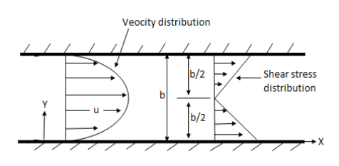
Consider laminar flow between two parallel flat plates located at a distance b apart such that lower plate is at rest & the upper plates moves uniformly with a constant velocity U as shown in fig.
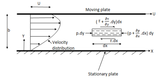
A small rectangular element of fluid of length dx, thickness dy & unit width is
Considered as a free body.
The forces acting on the fluid element are
1) The pressure force p dy x 1 on left end
2) The pressure force (p + . dx) dy x1 on the right end.
3) The shear force 
4) The shear force [ . dy] dx x 1 on the surface.
5)
For steady & uniform flow the resultant force in the direction of flow is zero.
p. dy – (p +  . dx) dy –
  + (
+ ( +
+ . dy) dx = 0
- dx. dy +
  dy. dx = 0
Dividing by the volume of element dx. dy we get
 =
=  -------------------(1)
Above equation shows the interdependence of shear & pressure gradients
According to Newton’s law of viscosity for laminar flow the shear stress.
 =
=  .
. 
put in equation (1) we get,
 =
= 
Integrating above equation twine w. r. t. y
u =  y2 + C1 y + C2 -------------(2)
At y = 0, u = 0 & at y = b, u = U
We get C2 = 0 & C1 =  -
-  (
( ) b
) b
Put values of C1& C2 in eqn. (2)
u =  y -
y -  (by – y2)
q =  =
=  (by – y2)] dy
U.  -
- 
The distribution of shear stress across any section may be determined by using
Newton’s Law of viscosity
 = u.
= u.  =
=  [
[ -
-  (
( ) (b – 2y)]
=  -
-  (b – 2y)
Q5) Explain the Flow of viscous fluid between two parallel plates when both plates are at the rest– Coutte flow.
A5) Both Plates at Rest:
In this case the equations for velocity, discharge q and the shear can be obtained from similar equation for generalise Coutte flow by putting U = 0
Thus, for flow between two stationary parallel plates.
u = -  .
.  (by – y2)
Discharge per unit width,
q =  .
. 
Shear stress  .
.  (b –2y)
Q6) Explain the concept of hydro dynamically smooth and rough boundaries.
A6)

i) Hydrodynamically smooth boundary, when ( ) < 0.25
ii) Hydrodynamically rough boundary, when ( ) > 6.0
iii) Boundary in transition, when 0.25 < ( ) < 6.0
Q7) Explain velocity distribution for turbulent flow in smooth pipes.
A7) Velocity Distribution for turbulent flow in smooth pipes.
The velocity distribution for turbulent flow in smooth or rough pipe is given by equation as
u = logey + c
It may be seen that at y = 0, the velocity u at wall is + 
This means that velocity u is positive at some distance away from the wall and -  (minus Infinity) at the wall.
Hence at some finite distance from wall the velocity will be equal to zero.
Let this distance from pipe wall is y
Now, the constant C is determined from the boundary condition.
at y = y, u = 0.
Hence above equation become as
0 =  logey’+ c
c =-  logey’
Substituting the value of c in above eqn.
u =  logey -
  logey’
=  loge
loge
Substituting the value of K = 0.4, we get
u =  loge
loge loge
loge
 =
=  log10
log10
 =
=  log10
log10 ---------(i)
From Nikuradse’s experiment the value of y’ is given as
y’ = 
Where  =
=  , where
  = Kinematic viscosity of fluid.
y =  x
x  =
= 
Substituting this value of y’ in equation (i), we obtain
 = 5.75 log10 (
  )
)
= 5.75 log10 (  ) = 5.75 log10 (
= 5.75 log10 + 5.75 log10 9.259
= 5.75 log10 + 5.55
The above equation is known as Karman Prandtl equation.
Q8) Explain Velocity Distribution for Turbulent flow in Rough Types
A8) In case of rough boundaries, the thickness of Laminar sub – layer is very small.
The surface irregularities are above the laminar sub- layer and hence the laminar sub layer is completely destroyed.
Thus y’ can be considered proportional to the height of protrusions k.
Nikuradse’s experiment shows the value of y’ for pipes coated with uniform sand (rough pipes) as
y’ = 
Substituting this value of y’ in equation
 = 5.75 log (y/y’)
 = 5.75 log10 (
 ) = 5.75 [ log10 (y/k) x 30]
= 5.75 log10 (y/k) + 5.75 log10 (30.0)
= 5.75 log10 (y/k) + 8.5
Q9) Explain the Laminar flow through circular pipe - Hagen Poiseuille Law.
A9)
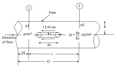
Fig: Shows a horizontal circular pipe of radius R, having laminar flow of fluid through it.
Consider a small concentric cylinder of radius r and length dx as a free body.
If  is the shear stress, the shear force F is given by
F =  x 2
x 2  r x dx
Let P be the intensity of pressure at left end and the intensity of pressure at the right end be (
Thus, the force acting on the fluid element are:
i) the shear force,  x 2
x 2 r x dx on the surface of fluid element.
ii) The pressure force, P x  on the left end.
iii) The pressure force, ( on the right end.
For steady flow, the net force on the cylinder must be zero.
 [ p x
[ p x  - (
- ( ] –
] – 
 -
-  -
-

Shear stress is zero at the centre of pipe (r = 0) and maximum at the pipe wall given by
 (
( )
)
From Newton’s Law of viscosity.

In this equation, the distance y is measured from the boundary. The radial distance r is related to distance y by the relation.
y = R-r or dy = - dr

Comparing two values of 
 =
= 
 du =
du =  (
( )r.dr
)r.dr
Integrating the above equation w. r. t. ‘r’ we get
 u =
u =  .
.  r2 + C --------------- (ii)
Where C is the constant of integration and its value is obtained from the boundary conditions.
At r = R, u = 0
 0 =
0 =  .
.  R2 + Cor C =
  .
.  R2
R2
Substituting this value of C in eqn. (ii) we get,
 u =
u =  .
.  r2
r2 .
.  R2
R2
 u = -
u = -  .
.  (R2 – r2)
Shows that velocity distribution curve is a parabola.
The maximum velocity occurs, at the centre and is given by.
 umax = -
  R2
R2
Q10) Explain the concept of Transition from laminar to turbulent flow
A10) Transition from laminar to turbulent flow
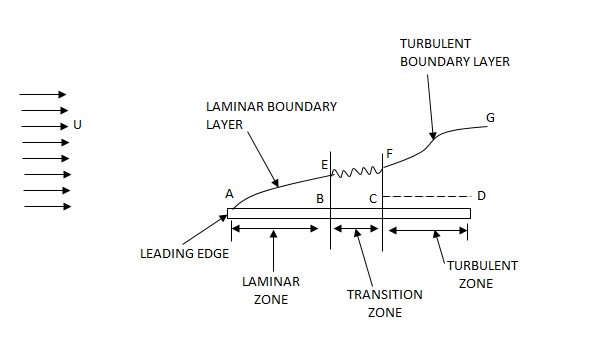
Q11) Explain the Development of boundary layer on a flat plate Laminar, transitional and turbulent boundary.
A11) Laminar Boundary Layer
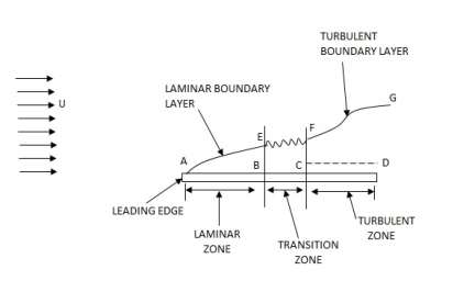
Turbulent Boundary Layer
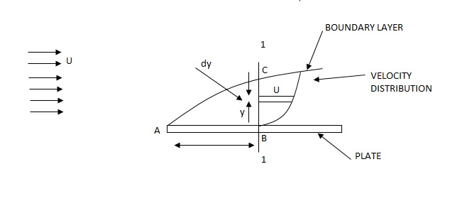
Q12) Explain the Nominal, displacement, momentum & energy thicknesses
A12) Boundary Layer Thickness ( )
)

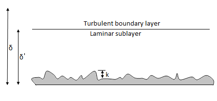
1.  = Thickness of laminar boundary layer,
2.  = Thickness of turbulent boundary layer, and
3.  = Thickness of laminar sublayer.
Displacement Thickness ( )
)


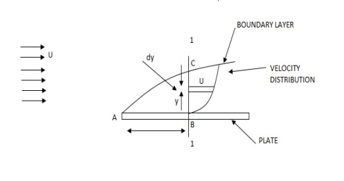
Momentum Thickness (


Energy Thickness ( )
)


Q13) Define Local and mean drag coefficients.
A13) Local and mean drag coefficients
Local coefficient of drag (CD*)
It is defined as the ratio of the shear stress  to the quantity
It is denoted by CD*

Average coefficient of Drag (CD)
It is defined as the ratio of total drag force to the quantity 
It is also called coefficient of drag and is denoted by CD.

where A= area of the surface (or plate)
V = free stream velocity
 = mass density of fluid
Q14) Explain the concept of boundary layer separation and its control.
A14) Boundary Layer separation and its control.
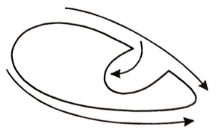
Separation of boundary layer
Q15) Explain the Methods of preventing the separation of boundary layer.
A15) Methods of preventing the separation of boundary layer
The following are the methods of preventing the separation of boundary layer:
By rotating a circular cylinder lying in a stream of fluid so that the upper side of cylinder where the fluid as well as the cylinder move in the same direction, the boundary layer does not form.

2. Acceleration of fluid in the boundary layer:
This method of controlling separation consists of supplying additional energy to particles of fluid which are being retarded in the boundary layer. This may be achieved either by injecting the fluid into the region of boundary layer from the interior of the body with the help of some available device as shown in the figure or by diverting a portion of fluid of the mainstream from the region of high pressure to the retarded region of boundary layer through a slot provided in the body.
3. Suction of fluid from the boundary layer:
In this method, the slowmoving fluid in the boundary layer is removed by suction through slots or through a porous surface as shown in the figure.
4. Streamlining of the body shapes:
By the use of suitable shaped bodies, the point of transition of the boundary layer from laminar to turbulent can be moved downstream which results in the reduction of the skin friction drag. Furthermore, by streamlining of the body shapes the separation may be eliminated.
5. Supplying additional energy from a blower.
6. Rotating boundary in the direction of flow.
7. Providing small divergence in a diffuser.
8. Providing guide blades in a bend.
9. Providing a trip wire ring in the laminar region for the flow over a sphere.
Q16) A Lubricating oil of viscosity 1 poise & sp. gr 0.9 is pumped through a 30mm diameter pipe. If the pressure drop per meter length of pipe is 20KN/m2. Determine
i) The mass flow rate in kg/min
ii) The shear stress at the pipe wall
iii) The Reynold number of flow
iv) The power required per some length of the pipe to maintain the flow
A16) Given,
 = 1 poise = 0.1 N. S/m2
 0.9
0.9 
 = 0.9 x 1000 = 900kg/m3
 = 0.03,
 = (P1 – P2) = 20 x
  N.S/m2
(P1 – P2) = 
20 x  =
= 
 = 5.625 m/s
A =  x
x  =
=  x
x = 7.068 X
Q = A.  = 7.068 x
  x 5.625= 3.97 x
  /sec
/sec
Mass flow rate = 
= 900 x 3.97 x  x 60
x 60
= 214.65 kg/min
 =
= 
= 20 x  x
x 
= 150 
Reynolds Number
Re =  =
=  = 1518.7
Loss of head hf =  =
=  =2.265 m
Power =  hf
hf
= (0.9 x 9810 x 3.97 x  x 2.265)
= 79.49 watts
For 50m length power required
P = 79.49 x 50
= 3974.5 watts.
Q17) A 0.2 m diameter pipe carries liquid in laminar region. A pilot tube placed in the flow at a radial distance of 6 cm from the axis of the pipe indicates velocity of 0.5 m/s. Calculate the maximum velocity, mean velocity & discharge in the pipe.
A17) Given,
D = 0.2 m, R = 0.1 m.
u(6cm) = 0.5 m/s
r = 6 cm = 0.06m
u = -  (
( )
)
0.5 = -  (
( )
)
-  = 78.125
Umax = - 
= 78.125 x 
= 0.7812 m/s
 =
=  Umax=
Umax=  0.7812
= 0.3906 m/s
A =  x
x  =
=  X
X  = 0.0314
Q = A.u
= 0.0314 x 0.3906
= 0.01227  /s
/s
Q18) Water is flowing over a thin smooth plate of length 4 m and breadth 2m at a velocity of 1.0m/s. If the boundary layer flow changes from laminar to turbulent at a Reynolds number 5× 10⁵. Find
i) the distance from leading edge up to which boundary layer is laminar.
ii) The thickness of the boundary layer at the transition point.
iii) The drag force on one side of the plate
u = 9.81× 10⁻⁴ NS /m2
A18) L=4m b=2m U=1.0m/s Re = 5×10⁵ u = 9.81×10⁻⁴ Ns/m2
(i) 


(ii) 
(iii) Drag force due to laminar boundary


Drag force due to turbulent boundary layer from F to G.
(FFG)turb = Drag force due to turbulent
boundary layer E to G – Drag force due to turbulent flow from E to F.
=(FEG)turb – (FEF)turb


Drag force on one side of plate = Drag force due to laminar boundary layerupto F + Drag force due to turbulent boundary layer from F to G.
=0.92 + 11.163 = 12.083 N
Q19) Find the displacement thickness, the momentum thickness and energy thickness for the velocity distribution in the boundary layer given by  , where u is the velocity at a distance y from the plate and u=U at y=
 , where
  is boundary layer thickness. Also calculate the value of
  .
.
A19) Velocity distribution 
(i) Displacement thickness is given by the equation
 =
=  (Since
 )
)
=  =
=  =
= =
=
(ii) Momentum thickness  is given by the eqn

Substituting the value of  ,
,
 =
= 

(iii) Energy thickness is given by the equation:
 =
= 
= =
=  =
=  -
-  =
= 

Q20) Find the displacement thickness and energy thickness for the velocity distribution in the boundary layer given by  2
2 .
.
A20) Velocity distribution  2
2 .
.
(i) Displacement thickness is given by the equation
 =
=  (Since
  )
)


(ii) Momentum thickness  is given by the eqn
 =
= 


(iii)  =
= 
=


Q21) A jet plane which weighs 29.43kN and having a wing area of 20 flies at a velocity of 950km/hr when the engine delivers 7357.5kW power. 65% of the power is used to overcome the drag resistance of the wing. Calculate the coefficients of lift and drag for the wing. The density of the atmospheric air is 1.21kg/
A21)
W=29.43  N
N
A=20
U=950 km/h=950 = 263.88 m/s
P=7357.5  watts
watts
Power used to overcome drag resistance = 65% of 7357.5 
= 7357.5
= 4782.375 watts
watts

Power used to overcome drag resistance = 
4782.375 =
=  236.88
 =18.12
 N
N
 =
=  A
A 
18.12 =
= 
 =0.0215
Force to be lifted = Weight of the plane

 =
=  A
A 
29430=
 =0.0349