Unit - 6
Dimensional Analysis & Similitude
Q1) Explain the concept of dimensions of physical quantities and dimensional homogeneity.
A1) Dimensions of physical quantities
Dimensional Homogeneity
P = w h
Dimensions of LHS = ML-1T-2
Dimensions of RHS = ML-2T-2×L = ML-1T-2
Dimensions of LHS = Dimensions of RHS
Hence, equation P= w h is dimensionally homogeneous; so, it can be used in any system of units.
Applications of Dimensional Homogeneity:
Q2) State the Buckingham’s theorem
A2) Buckingham’s Π- Method/Theorem
“If there are n variables in a dimensionally homogeneous equation and if these variables contain fundamental dimensions (such as M, L, T, etc.) then the variables are arranged into (n-m) dimensionless terms.
Mathematically, if any variable X1, depends on independent variables, X2, X3, X4…… Xn; the functional equation may be written as
 -------- 1
Equation 1 can also be written as
 -------- 2
It is dimensionally homogeneous equation and contain n variables.
If there are m fundamental dimensions, then according to Buckingham’s Π – theorem, it [eqn.] can be written in terms of number of Π – terms in which number of Π terms is equal to (n-m).
Hence equation 2 becomes as
 --------3
Each dimensionless  – term is formed by combining m variables out of the total n variables with one of the remaining (n-m) variable.
These m variables which appear repeated in each of  – terms are consequently called repeating variables and are chosen from among the variables such that they together involve all the fundamental dimentions and they themselves do not form a dimensionless parameter.
Let in the above case X2, X3 and X4 are the repeating variables if the fundamental dimensions m (M, L, T) = 3, then each term is written as:


.
.
.
 --------- 4
Where a1, b1, c1, a2, b2, c2 etc. are the constants, which are determined by considering dimensional homogeneity. These values are substituted in equation 4 and values of  are obtained. These values of Π’s are substituted in equation 3.
The final general equation for the phenomenon may then be obtained by expressing anyone of the Π – terms as a function of the other as:


Q3) Define the important dimensionless numbers.
A3) Reynold’s Number (Re)
It is defined as the ratio of the inertia force to the viscous force.
Reynold’s Number, Re = 

For pipe flow (where the linear dimension is taken as diameter d),

Reynold’s number signifies the relative predominance of the inertia to the viscous forces occurring in the flow systems.
Fraud’s Number (Fr)
It is defined as the square root of the ratio of the inertia force and the gravity force.
Mathematically, 
Froude number governs the dynamics similarity of the flow situations; where gravitational force is more significant and all other forces are comparatively negligible.
Euler’s Number (Eu)
It is defined as the square root of the ratio of the inertia force to the pressure force.

The Euler number is important in the flow problems / situations in which a pressure gradient exists.
Weber’s Number (We)
It is defined as the square root of the ratio of the inertia force to the surface tension force.
Mathematically, 
This number assumes importance in the following flow situation:
Flow of blood in veins and arteries
Liquid atomisation, and
Capillary movement of water in soils
Mach Formula (M)
It is defined as the square root of the ratio of the inertia force to the elastic force.
Mathematically, 
The Mach number is important in compressible flow problems at high velocities, such as high velocity flow in pipes or motion of high-speed projectiles and missiles.
Q4) Define Model analysis.
A4) Introduction to Model Analysis:In recent years, hydraulic model studies are being made in the study and analysis of many problems in fluid mechanics. A hydraulic problem may of course be analyzed by analytical methods, but these analytical methods involve a number of approximations and assumptions and hence their applications often become restricted. In many cases, the analytical methods involve highly complicated equations which cannot be solved.
In spite of the vast progress made in the field of fluid mechanics, the solutions to various complex flow patterns cannot be obtained by analytical methods alone. The available analytical methods need many simplifications so much so that their applications become not only restricted but also theoretical.
There are many cases where it is impossible or impracticable to make a satisfactory and complete mathematical analysis of the problems. A hydraulic model may sometimes provide the only means of ascertaining and eliminating certain undesirable conditions.
It is only through model experiments and research that improvements in the existing works, safe and economic design and construction of new works and furtherance of knowledge on many aspects of hydraulic engineering can be affected. These days, model studies have a wide field of applications – dams, rivers and harbours, hydraulic machines, structures, ships, aircraft, seepage problems etc.
In short, model experimentation has become an indispensable tool to a designing engineer.
Model studies are made for two purposes, namely
(i) To obtain information about the likely performance of the prototype, and
(ii) To help in the design and to avoid costly mistakes and to evolve an economic solution of a hydraulic problem.
Since, comparatively, it is inexpensive to modify the construction of a model, there is ample scope to try several alternative designs in the model before adopting a final one. Obviously, such trials would be excessively costly if they were undertaken with the full-scale system. A model study is intended to provide not only qualitative but also quantitative indications of the characteristics of the prototype.
A hydraulic model offers itself as a powerful design tool which establishes a fluid system from the observations on which the performance of the prototype could be inferred. Models are the only recourse to the nearest approach to the solution of many hydraulic problems.
Q5) State the field of application of Model analysis.
A5)It should not be presumed that model studies provide the ready answers to every hydraulic problem. It will not be possible to devise a suitable model test to interpret the results of the model tests, unless the basic theory of the phenomenon under study is understood. It is likely that in some cases it may be impracticable to build a model study in situations where the results can be predicted correctly by theory.
In spite of these limitations, model tests have proved to be very valuable in a number of cases and hence the use of models in hydraulic engineering is increasing steadily.
The following are some examples where model studies have been of great value:
i. Dams:
The design of every major dam is checked by model tests before its construction. Besides the model of the dam, all its connected works like spillways, penstocks and gates are studied in order to get detailed information on the flow of water and its effect on the structure. A model study can be helpful in deciding what type of dam may be best suited for any locality and what site can be the best choice for placing a dam. Studies of the models of sluice openings in dams to ascertain the best opening for maximum discharge, studies of various profiles of inlet bell mouths and outlets and studies of the behaviours of gates under operating conditions are of great value. In a penstock where a change of cross-section from a rectangle to a circle for the intake from a dam structure, necessary curves are better decided by model studies.
ii. Rivers and Harbours:
Hydraulic engineers all over the world are involved in considerable amount of work devoted to the dredging of rivers, straightening of channels, protection of banks and bottoms from erosion, various forms of river control and improvement. Harbours and estuaries pose special problems of model design, as it is necessary to duplicate the natural tidal cycles in the model and this may naturally need elaborate machinery.
Model studies can help in studying the wave action of harbours concerned mainly with the effectiveness of the proposed breakwaters for providing protection from waves, and the extent of damage the waves may inflict on the breakwaters. Model studies of breakwater are very essential as there are a number of instances where the breakwaters have failed to provide the adequate protection anticipated of them.
iii. Hydraulic Machines:
Small scale model tests are very useful to obtain performance data for hydraulic turbines and other turbo machines and centrifugal pumps. Model study is a very valuable guide to designers of turbo machines.
iv. Structures:
Where prototype testing is difficult or costly, models provide the proper solution. Many structural tests like deflection tests and destructive and non-destructive testing of structures can be satisfactorily performed on models. Photo elastic and analogy methods of testing of models of dams are very common.
v. Ships:
Towing models in a canal are helpful in estimating Drag force and wave patterns of naval vessels.
vi. Seepage Problems:
It is possible to make studies of seepage flow on geometrically similar sectional models in glass flumes, to find out the uplift pressures on hydraulic structures.
The above are only a few examples of applications of models. It should not be taken for granted that model investigations alone can solve our hydraulic problems. Unless we are able to diagnose the fundamental nature of the problems, the results obtained from the model may be incomplete and may be unreliable. Thus, the correct applicability of model technique is a well-balanced, well studied and well-done combination of model experimentation and analysis.
Analysis involves factors unsolved due to the ignorance of the experiments, which can be solved with the aid of models. Though a well-designed model enables the hydraulic engineer to solve specific problems like those of river control etc., yet the performance is not always a cent percent miniature of the prototypes, because of what can be called model limitations.
It is for this reason that the results obtained from some model experiments are qualitative only. The design, operation and correct interpretation of results, therefore, is a specialised job, requiring quite an amount of experience and good visualisation of the various assumptions made.
Today model analysis has provided the field engineers with a novel tool for studying the various complicated problems and for fixing and regulating the forces of nature to suit his need by properly designed courses.
Q6) How to select the scale for model.
A6) Selection of Scale for a Model:Selecting a proper scale is a very important part in planning a model.
The following are the factors which influence the selection of scale for the models:
(a) The space available to accommodate the model.
(b) Quantum of water supply available at the model station.
(c) Type of results desired, i.e., qualitative or quantitative.
(d) Expenditure involved.
It is very important to note that the scale of the model be such that the value of the Reynold number in the model within the range of discharge in which it is experimented, is not below the value corresponding to turbulent flow. If, in any case, with a scale assumed, it is found that the flow in the model is not turbulent while the flow in the prototype is turbulent, it will be necessary to make adjustment in the scale.
In such cases we have to adopt distorted models, i.e., models in which the vertical and horizontal scales are not the same. Selection of a proper scale is the primary and essential consideration in order to achieve the desired results, from a study on a hydraulic model, and it is here, mainly, the wide experience of the hydraulic engineer comes into play.
The scale ratios generally adopted are as follows:
(i) Dams and spillways — 1/30 to 1/400
(ii) Head works, gates, canals — 1/5 to 1/25
(iii) Rivers, harbours and estuaries — 1/100 to 1/1000
Q7) Explain the behavior of model and prototype.
A7) When the components of a model have the same shape as the corresponding components of the prototype, then the two systems are geometrically similar. Usually, geometric similarity is maintained in most of the models of fabricated structures.
There is a point-to-point correspondence between a model and its prototype. By examining a particular property at a particular point in the model, we can determine the corresponding property at the corresponding point in the prototype.
It is for such determination, models are made and experimented. It should be noted that the concept of similarity extends too many characteristics besides geometry. It is not enough if the model looks like the prototype, but it should function like the prototype. In fact, geometric similarity is not really the requirement but similarity of performance is the requirement.
From this point of view, in the case of models of rivers, estuaries and harbours it will not be feasible to provide geometric similarities, since the depth of water in such models may be at the order of about 5 mm. When such small depths are involved, the flow is dependent on Weber’s number i.e., the flow is strongly influenced by surface tension. Hence models of rivers and harbours are generally distorted i.e., the depths of water are made relatively greater.
A model is intended to provide quantitative indications of the characteristics of the prototype. The similarity and the test conditions of the model are generally determined by dimensional analysis taking into account the various independent variables influencing the problems. If all the independent dimensionless parameters have the same values for the model and prototype then the two are said to be absolutely similar.
It is of course obvious that absolute similarity is impossible without geometric similarity. But it may be noted that it is not feasible to impose absolute similarity in a model test and hence some of the independent dimensionless parameters which are anticipated to have only secondary influences or which influence the phenomenon in a predictable manner are allowed to deviate from their correct values.
When such departures are made from absolute similarity, the hydraulic engineer must be able to justify such departures. For instance, the influence of viscosity on drag on a ship may be estimated by theory and consequently it will not be necessary to preserve the correct value of the Reynold’s number in a towing test of a model.
There is, however, an important precaution to be observed while ignoring certain non-dimensional products. There are situations where forces of negligible importance on the behaviour of the prototype may affect significantly the behaviour of the model. Ocean waves, for instance, are not influenced by surface tension.
But, if in a model, the waves are less than 25 mm length, their nature is dominated by surface tension. This means the Weber’s number is a very important parameter of the model while its importance is negligible in the prototype. Such disturbing influences are called scale effects and should be guarded against by building the models as large as feasible.
Q8) Explain Kinematic and Dynamic similarity.
A8) Kinematic Similarity:
This is similarity of motion. This similarity is said to exist when the ratios of corresponding kinematic quantities at corresponding points of the model and prototype are the same.
If vm1, vm2, vm3 etc. be the velocities at certain points in the model, and if vp1, vp2 vp3 etc. be the velocities at corresponding points in the prototype, then the condition to be satisfied is –


(iii) Dynamic Similarity:
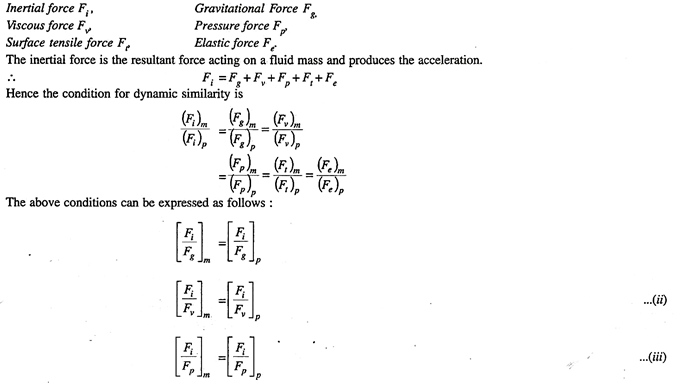
This is similarity of masses and forces. This similarity is said to exist between the model and the prototype when (a) the ratio of masses of corresponding fluid particles in motion are the same, and (b) the ratio of forces on corresponding fluid particles are the same. Dynamic similarity also includes geometric and kinematic similarities. A fluid mass, in general, may be subjected to the following forces:
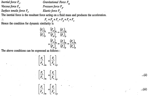
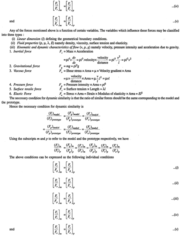
For absolute dynamic similarity all the above equations (i) to (v) should be satisfied. But in nature it is not possible to satisfy all these equations simultaneously. For instance, if we satisfy the condition [(Fi/Fg) m] = [(Fi/Fg) p] we cannot, at the same time, satisfy the condition [(Fi/Fv) m] = [(Fi/Fv) p].
Hence complete dynamic similarity cannot be practically achieved.
But in the practical cases we may handle, in any one phenomenon only one of the above-mentioned forces is predominant and the other forces are insignificant. For instance, in a study of flow over a weir, gravitational force is the predominant force. In a case of flow of a fluid through a conduit at very low velocities, the viscous force is predominant.
Thus, we find in a phenomenon, a particular force alone is usually predominant. Hence, for practical purposes, a model may be taken to be dynamically similar to the prototype if the ratio of the inertial to the predominant force is the same in the model and the prototype.
Q9) Explain the distortion in a model.
A9) The distortion introduced in a model may be of the following types:
(i) Geometric distortion –This is a distortion introduced by adopting different scales for horizontal and vertical dimensions.
(ii) Configuration distortion – In this case the bed slope of the model is increased, otherwise the model is geometrically similar. This case amounts to placing a geometrically similar model in a tilted position compared to the positions of the prototype.
(iii) Hydraulic distortion – This is a type of distortion such that some hydraulic quality say velocity or time of discharge may be changed.
(iv) Material distortion – This type of distortion involves the use of materials different from those in the prototype. Surface materials, surface roughness or the medium in which the model works may be changed.
Merits of Distorted Models:
(i) The necessary hydraulic similitude is obtained.
(ii) Depth of flow is increased affording precise measurements.
(iii) Height of waves is increased affording precise measurements.
(iv) Viscous effects which are practically absent in the prototype can be practically eliminated in the model. For instance, by increasing the bed slope in an otherwise geometrically similar model, the velocity can be increased, thus decreasing viscous effects.
(v) Movement of silt and sand can be satisfactorily brought about to match the corresponding behaviour of the prototype.
(vi) By adopting a distorted model, the size of the model can be reduced thus simplifying the operation of the model.
(i) Due to unequal horizontal and vertical scales the pressure and velocity distribution are not truly reproduced in the model.
(ii) The wave pattern in the model will be different from that in the prototype due to depth distortion.
(iii) Slopes, bends and earth cuts are not truly reproduced.
Q10) Explain any one type of viscosity.
A10) Rotating cylinder method
According to Newton’s law of viscosity,

Since the annular space t = (R2 – R1) is quite small (where R2 and R1 are the radii of the outer and inner cylinders respectively), the velocity gradient

(Where N= the rotational speed of the outer cylinder in rpm)
Shear stress =
= 
Viscous drag = Shear stress × Area
= 
(Where h = height of liquid)
Viscous torque = Viscous drag x radius
= x
x 
Viscous torque must be equal to the torque T exerted by the torquemeter.


Thus, a rotational type viscometer can be calibrated to directly give u for given speed of rotation N.
Q11) Explain Darcy’s law and its application.
A11) Darcy’s law
Darcy’s Law Application
Darcy’s Law Equation
Q = -KA dh/dl
Wherein:
Q is the rate of water flow
K is the hydraulic conductivity
A is the column cross section area
dh/dl indicates hydraulic gradient.
Q12) Determine the methods of preventing the separation of boundary layer.
A12) Methods of preventing the separation of boundary layer
The following are the methods of preventing the separation of boundary layer:
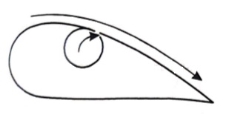
By rotating a circular cylinder lying in a stream of fluid so that the upper side of cylinder where the fluid as well as the cylinder move in the same direction, the boundary layer does not form.

2. Acceleration of fluid in the boundary layer:
This method of controlling separation consists of supplying additional energy to particles of fluid which are being retarded in the boundary layer. This may be achieved either by injecting the fluid into the region of boundary layer from the interior of the body with the help of some available device as shown in the figure or by diverting a portion of fluid of the mainstream from the region of high pressure to the retarded region of boundary layer through a slot provided in the body.

3. Suction of fluid from the boundary layer:
In this method, the slow-moving fluid in the boundary layer is removed by suction through slots or through a porous surface as shown in the figure.
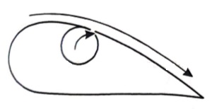
4. Streamlining of the body shapes:
By the use of suitable shaped bodies, the point of transition of the boundary layer from laminar to turbulent can be moved downstream which results in the reduction of the skin friction drag. Furthermore, by streamlining of the body shapes the separation may be eliminated.
5. Supplying additional energy from a blower.
6. Rotating boundary in the direction of flow.
7. Providing small divergence in a diffuser.
8. Providing guide blades in a bend.
9. Providing a trip wire ring in the laminar region for the flow over a sphere.
Q13) A Fluid of viscosity 8 poise & sp.gr. 1.2 is through a circular pipe of diameter 100mm. The maximum shear stress at the pipe u is z 10 N/M2 Find
(i) The pressure gradient
(ii) The average velocity
(iii) Reynolds number of flow
A13) Given
 = 8 poise= 0.8 N. S/m2
  ,
, 
S = 1.2
 = 1.2 x1000 = 1200 kg/m3
 = 0.1, R = 0.05 m
 = 210 N/m2
1)  o =
o = 
210 =  .
. 
 = -8400 N/m2 per m
2) The average velocity
 =
=  Umax
Umax
=  [
[ R2]
R2]
=  [ -
[ -  ]
]
= 3.28 m/s
3) Reynolds number
Re = =
= 
= 492
Q14) A Lubricating oil of viscosity 1 poise & sp. gr 0.9 is pumped through a 30mm diameter pipe. If the pressure drop per meter length of pipe is 20KN/m2. Determine
i) The mass flow rate in kg/min
ii) The shear stress at the pipe wall
iii) The Reynold number of flow
iv) The power required per some length of the pipe to maintain the flow
A14) Given,
 = 1 poise = 0.1 N. S/m2
 0.9
0.9
 = 0.9 x 1000 = 900kg/m3
 = 0.03,
 = (P1 – P2) = 20 x
  N.S/m2
(P1 – P2) = 
20 x  =
= 
 = 5.625 m/s
A =  x
x  =
=  x
x = 7.068 X
Q = A.  = 7.068 x
  x 5.625= 3.97 x
  /sec
/sec
Mass flow rate = 
= 900 x 3.97 x  x 60
x 60
= 214.65 kg/min
 =
= 
= 20 x  x
x 
= 150 
Reynolds Number
Re =  =
=  = 1518.7
Loss of head hf =  =
=  =2.265 m
Power =  hf
hf
= (0.9 x 9810 x 3.97 x  x 2.265)
= 79.49 watts
For 50m length power required
P = 79.49 x 50
= 3974.5 watts.
Q15) A 0.2 m diameter pipe carries liquid in laminar region. A pilot tube placed in the flow at a radial distance of 6 cm from the axis of the pipe indicates velocity of 0.5 m/s. Calculate the maximum velocity, mean velocity & discharge in the pipe.
A15) Given,
D = 0.2 m, R = 0.1 m.
u(6cm) = 0.5 m/s
r = 6 cm = 0.06m
u = -  (
( )
)
0.5 = -  (
( )
)
-  = 78.125
Umax = - 
= 78.125 x 
= 0.7812 m/s
 =
=  Umax=
Umax=  0.7812
= 0.3906 m/s
A =  x
x  =
=  X
X  = 0.0314
Q = A.u
= 0.0314 x 0.3906
= 0.01227  /s
/s
Q16) Water is flowing over a thin smooth plate of length 4 m and breadth 2m at a velocity of 1.0m/s. If the boundary layer flow changes from laminar to turbulent at a Reynolds number 5× 10⁵. Find
i) the distance from leading edge up to which boundary layer is laminar.
ii) The thickness of the boundary layer at the transition point.
iii) The drag force on one side of the plate
u = 9.81× 10⁻⁴ NS /m2
A16) L=4m b=2m U=1.0m/s Re = 5×10⁵ u = 9.81×10⁻⁴ Ns/m2
(i) 


(ii) 
(iii) Drag force due to laminar boundary


Drag force due to turbulent boundary layer from F to G.
(FFG)turb = Drag force due to turbulent
boundary layer E to G – Drag force due to turbulent flow from E to F.
=(FEG)turb – (FEF)turb


Drag force on one side of plate = Drag force due to laminar boundary layer up to F + Drag force due to turbulent boundary layer from F to G.
=0.92 + 11.163 = 12.083 N
Q17) Find the displacement thickness, the momentum thickness and energy thickness for the velocity distribution in the boundary layer given by  , where u is the velocity at a distance y from the plate and u=U at y=
 , where
  is boundary layer thickness. Also calculate the value of
  .
.
A17) Velocity distribution 
(i) Displacement thickness is given by the equation
 =
=  (Since
 )
)
=  =
=  =
= =
=
(ii) Momentum thickness  is given by the eqn

Substituting the value of  ,
,
 =
= 

(iii) Energy thickness is given by the equation:
 =
= 
= =
=  =
=  -
-  =
= 

Q18) Find the displacement thickness and energy thickness for the velocity distribution in the boundary layer given by  2
2 .
.
A18) Velocity distribution  2
2 .
.
(i) Displacement thickness is given by the equation
 =
=  (Since
  )
)


(ii) Momentum thickness  is given by the eqn
 =
= 


(iii)  =
= 
=


Q19) A jet plane which weighs 29.43kN and having a wing area of 20 flies at a velocity of 950km/hr when the engine delivers 7357.5kW power. 65% of the power is used to overcome the drag resistance of the wing. Calculate the coefficients of lift and drag for the wing. The density of the atmospheric air is 1.21kg/
A19) W=29.43  N
N
A=20
U=950 km/h=950 = 263.88 m/s
P=7357.5  watts
watts
Power used to overcome drag resistance = 65% of 7357.5 
= 7357.5
= 4782.375 watts
watts

Power used to overcome drag resistance = 
4782.375 =
=  236.88
 =18.12
 N
N
 =
=  A
A 
18.12 =
= 
 =0.0215
Force to be lifted = Weight of the plane

 =
=  A
A 
29430=
 =0.0349
Q20) A plate of 600mm length and 400mm width is immersed in a fluid of sp.gr 0.9 and kinematic viscosity
 . The fluid is moving with a velocity of 6 m/s. Determine
i) Boundary layer thickness
ii) Shear stress at the end of the plate
iii) Drag force on one side of the plate.
A20) L=0.6m
b=0.4m
S=0.9
 =0.9
=0.9  = 900 kg/
U=6 m/s
v=
Reynold Number = 

Therefore, the boundary layer is laminar over the entire length of the plate.
Thickness of boundary layer  where x=0.6
=
Shear stress, 

Drag Force, 


Q21) A kite 0.8m  0.8m weighing 3.924 N assume angle of
  to the horizontal. The string attached to the kite makes an angle
  to the horizontal. The pull on the string is 24.525N when the wind is flowing at a speed of 30km/h. Find the corresponding coefficient of drag and lift. Density of air is given 1.25kg/
 .
.
A21) A=0.8  =0.64
=0.64 
W=3.924 N
θ1=120
θ2=450
P=24.525 N
U=30 km/h =
 =1.25 kg/


