UNIT-1
Fundamentals of Mechanism
Q1) Define Kinematic link? Classify the kinematic links?
Ans1). Each half of a machine that moves relative to another part, is thought as a kinematic link (or merely link) or component. A link could include many elements that square measure bolt fixed along, in order that they are doing not move relative to at least one another.
The types of kinematic link are:
1. Rigid Link
2. Versatile link
3. Fluid Link
4. Floating Link
2. Versatile Link: a versatile link is one that whereas transmission motion is part misshapen during a manner to not have an effect on the transmission of motion. for instance, spring, chain, rope, belt etc.
3. Fluid Link: A fluid link is one that's misshapen by having a fluid during a closed vessel and also the motion is transmitted through the fluid by pressure. for instance, press and hydraulic jack.
4. Floating Link: A floating link is one that's not connected to the frame.
Q2) Define Kinematic Chain?
Ans 2) When the kinematic pairs square measure coupled in such the way that the last link is joined to the primary link to transmit definite motion (i.e., utterly or with success affected motion) it is known as a kinematic chain. In alternative words, is also outlined as a mixture of kinematic pairs, joined in such the way that every link forms a neighbourhood of 2 pairs and therefore the relative motion between the links or parts is totally or with success affected motion.
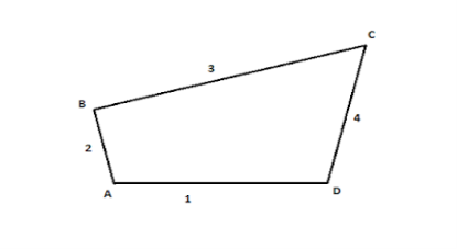
Kinematic Chain
If every link is assumed to make 2 pairs with 2 adjacent links, then the relation between range the amount the quantity} of pairs (p) forming a kinematic chain and also the number of links (l) is also expressed within the style of associate degree equation:
l=2p-4
Q3) Define the Joints?
Ans 3) Joints are most significant a part of a mechanism. The resultant motion on operative a mechanism is set by the kinematic joints connecting the members of the mechanism. The kinematic joints enable motion in some directions and constrain it in others. the kinds of motions allowed and strained are associated with the degrees of freedom of a joint. the subsequent are the kinds of joints sometimes found in a very chain.
• Binary joint
• Ternary joint
• Quaternary joint
Q4)Define Mechanism and Machines?
Ans 4) When one in every of the links of a kinematic chain is fastened, the chain is thought as mechanism. it's going to be used for transmittal or reworking motion e.g., engine indicators, typewriters etc. A mechanism with four links is thought as straight forward mechanism, and also the mechanism with quite four links is thought as compound mechanism.
A machine may be a mechanism or assortment of mechanisms, that transmit force from the supply of power to the resistance to be overcome, although all machines are mechanisms, all mechanism don't seem to be machines.
Q5) Write the Grubler’s criterion for determining degrees of freedom of a mechanism having plane motion?
Ans 5) Following is the formula for calculating the degree of freedom and mobility and called as Grubler’s criterion.
n=3(l-1)-2j
l-Number of links
j-Lower pair joint
Example: To find number of degrees of freedom
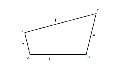
Therefore, by grubler’s criterion formula,
= n= 3 (l-1)-2j
l = 8, j=10
therefore, n = 3 (8-1) – 2  10= 1
10= 1
implies that, DOF = 1
Q6) Define Inversion of mechanism?
Ans.6) A mechanism within which one in all the links of a kinematic chain is mounted. totally different completely different} mechanism may be obtained by fixing different links of a similar kinematic chain. These square measures referred to as inversions of the mechanism. By dynamical the mounted link, the number of mechanisms which may be obtained is up to the number of links. Except the first range of links all the opposite mechanisms square measure referred to as inversions of original mechanism. The inversion of a mechanism doesn't modification the motion of its links relative to every different. the categories of inversions square measure:
a) Kinematic inversion of 4 bar chain
b) Slider crank chain or singe slider crank chain
c) Double slider crank chain
Q7) Define Grashof’s law and state its significance?
Ans.7.) It states that in a planar four bar mechanism, the sum of shortest link length and longest link length is not greater than the sum of remaining two links length, if there is to be continuous relative motion between two members.
Significance:
Grashoff’s law specifies the order in which the links are connected in a kinematic chain. Grashoff’s law specifies which link of the four-bar chain is fixed. (s+1) =(p+q) should be satisfied, if not, no link will make a complete revolution relative to another. s= length of the shorter length
l= length of the longest link
p & q are the lengths of the other two links.
Q8 Define double slider crank chain Mechanism?
Ans.8.) A kinematic chain that consists of 2 turning pairs and 2 slippery pairs is understood as double slider crank chain, we have a tendency to see that the link a {pair of} and link one kind one turning try and link two and link three kind the second turning pair. The link three and link four kind the second turning try. The link three and link four kind one slippery try and link one and link four kind second slippery try.
Inversions of Double Slider Crank chain are:
Q9) What are the inversions of single slider crank chain?
Ans.9.) The inversions of single slider crank chain are:
1.Pendulum pump or Bull Engine
In this mechanism, the inversion is obtained by fixing the cylinder or link four (i.e., slippy pair) as shown in fig.1.23. during this case, once the crank (link 2) rotates, the rod (link 3) oscillates a couple of pins pivoted to the fastened link four at A and therefore the piston hooked up to the connecting rod (link 1) reciprocates. The duplex pump that is employed to produce feed water to boilers have 2 pistons hooked up to link one, as shown in fig.1.23.
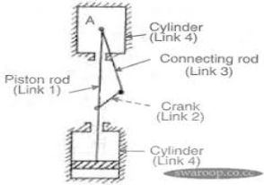
Figure.1.23 Pendulum Pump
2.Oscillating Cylinder Engine
The arrangement of oscillatory cylinder engine mechanism as shown in fig.1.24 is employed to convert reciprocal motion into motion. during this mechanism, the link three forming the turning try is fastened. The link three corresponds to the rod of a reciprocal external-combustion engine mechanism. once the crank (link 2) reciprocates and therefore the cylinder (link 4) oscillates concerning the pin pivoted to the fastened link at A.
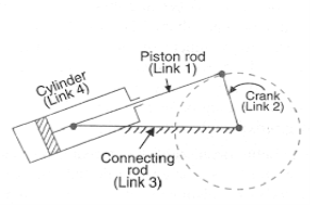
Figure.1.24 Oscillating Cylinder Engine
Sometimes back, rotary burning engine were employed in aviation. however today turbine area unit employed in its place. It consists of seven cylinders in one plane and every one revolves regarding fastened centre D, as shown in fig.1.25 whereas the crank (link 2) is fastened. during this mechanism, once the rod (link 4) rotates, the piston (link 3) reciprocates within the cylinder forming link one.
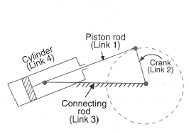
Figure.1.25 Rotary Internal Combustion Engine
2. Crank and Slotted Lever Mechanism
This mechanism is generally employed in shaping machines, slotting machines and in rotary burning engines. during this mechanism, the link AC (i.e., link 3) forming the turning try is fastened, as shown in fig.1.26. The link three corresponds to the rod of a reciprocal external-combustion engine. The driving crank CB revolves with uniform angular speed regarding the fastened centre C. A slippy block connected to the crank pin at B slides on the slotted bar AP and so causes AP to oscillate regarding the pivoted purpose A. a brief link PR transmits the motion from AP to the ram that carries the tool and reciprocates on the road of stroke R1R2. the road of stroke of the ram (i.e., R1R2) is perpendicular to AC made.
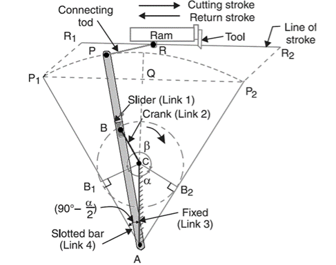
Figure.1.26. Crank and Slotted Lever Quick Return Mechanism
In the extreme position AP1 and AP2 area unit tangential to the circle and therefore the cutlery is at the top of the stroke. The forward or cutting stroke happens once the crank rotates from the position CB1 to CB2 (or through associate angle β) within the dextrorotatory direction. Since the crank has uniform angular speed, therefore,
Since the tool travels a distance of R1R2 during cutting and return stroke, therefore travel of the tool or length of stroke
= R1R2 = P1P2 = 2P1Q = 2AP1 sin(P1AQ)
= 2 AP1 sin (90 – α/2) = 2 AP cos α/2
= 2 AP cos α/2
= 2 AP × 
3. Whitworth Quick Return Motion Mechanism
This mechanism is generally employed in shaping and slotting mechanism. during this mechanism the link CD (link 2) forming the turning try is fastened. As shown in figure one.27. The link a pair of corresponds to a crank during a reciprocatory external-combustion engine. The driving crank CA (link 3) rotates at a homogenous angular speed. The slider (link 4) hooked up to the crank pin at A slides on the slotted bar PA (link 1) that oscillates at a pivoted purpose D. The rod PR carries the ram at R to that a cutting implement is fastened. The motion of the tool is forced on the road RD made i.e., on a line passing through D and perpendicular to CD.
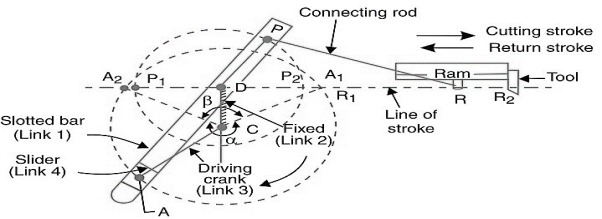 Figure.1.27. Whitworth quick return motion mechanism
A little thought can show that the time taken throughout the left to right movement of the ram (i.e., throughout forward or cutting stroke) is quite the time taken throughout the come back stroke). In different words, the mean speed of the ram throughout the cutting stroke is a smaller amount than the mean speed of the ram throughout the cutting and come back stroke is given by,
 =
=  =
= 
Q10 Define Equivalent Linkages along with types?
Ans.10) It is doable to switch turning pairs of plane mechanisms by alternative kinds of pairs having one or 2 degrees of freedom, like slippy or cam pairs. This could be done in keeping with some set rules in order that the new mechanism even have constant degrees of freedom and are kinematically similar.
The cases of equivalent linkages are:
Figure.1.32 shows slippy pairs in situ of turning pairs. Link 4 i.e., rocker length is magnified to time so D lies at time. currently with the rotation of the crank purpose of contact can have linear motion perpendicular to the axis of link four. equally turning pairs is replaced by slippy pairs by providing slider with guides at B. just in case the axis of 2 slippy pairs in one line or parallel the 2 sliders in conjunction with link three act mutually link with no relative motion among these links. Thus, so as to switch 2 turning trys during a linkage with slippy pairs by fixing a slider to any of the 2 links forming a pair.
2. Spring in place of Turning pairs
The action of a spring is to elongate or shorten because it becomes in tension or compression. the same variation long is accomplished by 2 binary links joined by a turning try. In figure. 1.33 the length AB varies as OB touched away or towards purpose A. Figure 1.33 shows a six -link mechanism within which link four and five are replaced by a spring.

Figure.1.33. Six link Mechanism
3. Cam in place of Turning pairs
A cam pair has 2 degrees of freedom. For linkages with one degree of freedom, application of grubler’s equation yields.
P1 = 3N-5 /2
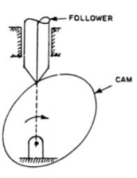
Figure.1.34. Cam replaced with turning pair


