UNIT-2
Kinematic Analysis of Mechanisms: Analytical Method
Q1) Explain velocity and acceleration analysis of mechanisms?
Ans.1) Velocity and acceleration analysis of mechanisms can be performed vectorially using the relative velocity and acceleration concept. Usually, we start with the given values and work through the mechanism by way of series of points A, B, C, etc. Solving vector equations in the form:
VB = VA+ VB/A
VC= VB+ VC/B
etc. for velocity and
aB= aA+ atB/A+ anB/A
aC= aB +atC/B +anC/B
etc for acceleration. The points that one has to use are usually the revolute joint axes between the links since these are the points where the relative velocity or acceleration between the two coincident points on two different links are zero and they have equal velocity and accelerations. If we are to determine the velocity of a point on a link we must first determine the velocity of the points located at the joint axes.
Q2) What is Displacement, Velocity and Acceleration Analysis of Plane Mechanisms?
Ans.2) The objective of Displacement, Velocity and Acceleration Analysis (kinematic analysis) is to determine the kinematic quantities (e.g., displacements, velocities, and accelerations) of the elements of a mechanism when the input motion is given. Identifying the displacements, velocities, and accelerations of one or more points on linkages is important in force analysis of mechanisms.
Q3) Explain how the velocities of a slider and the connecting rod are obtained in a slider crank mechanism?
Ans.3) In the graphical technique, the orientation of every link obtained from the position analysis is employed for the rate analysis. If a link features a motion with reference to the other link, the direction of motion of the link and thus its speed vector are going to be perpendicular to the link. On the opposite hand, if the motion is translatory, the direction of its speed vector are going to be on the direction of the motion. within the case of the slider-crank mechanism at hand, a vector for Link two (crank) is drawn on an appropriate scale that magnitude of speed and direction area unit well-known from the input parameters. The direction of the rate vector of Link three i.e., rod, is perpendicular thereto. The direction of speed vector of Link four (slider) is on its translatory motion. The point may be determined for these 2 directions and thus a vector plane figure is obtained. Sides of the plane figure represent speed vectors that correspond to the direction of the rate, and by mapping its magnitude to the initial scale, the linear speed of the links area unit calculated. additional data on the graphical ways may be found in next unit. For the implementation of Mech analyser, the magnitude of the linear speed at the terminus of every link resolve to urge the rate plane figure. Product of the magnitude of angular speed and also the length of the link provides the linear speed of the top purpose of every link. concerning Figures.2.3, let the angular speed of Link two be 𝜔2 and its length be 𝑟2 (≡|𝐀𝐁⃗|). The linear speed of purpose B with reference to purpose A can be:
𝑣2= 𝜔2 𝑟2
Q4) Define acceleration analysis in mechanisms?
Ans4) In case of the acceleration analysis, there are two components of the linear acceleration of each link. They are radial and tangential. Let a2^r and a2^t be radial and tangential components of acceleration respectively for link 2. Angular acceleration 𝛼2 of Link 2 will be taken as the input from user. Its radial and tangential components are determined using,
a2r=w2 r2
a2t= a2r2
Q5) How to find velocity and acceleration by complex algebra method?
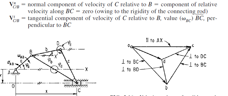
Ans5) Using the slider crank of Fig.. once more as an illustration with x axis along the
center line of the guide, and recalling that i^2=-1, we write the complex-number
equations as follows, with the equivalent vector equation below each:
Displacement: ae^i a + be^i
 b+ce^i
 c=x ……. (1)
AB + BD + DC = AC ……(2)
Velocity: iae^ iawAB + (ibe^i
 b + ice^ic) +BC = dx/dt …. (3)
VB +VD/B +VC/D=VC……..(4)
Note that wAB =d a/dt is positive when counter-clockwise and negative when clockwise; in this problem wAB is negative.
The complex conjugate of Eq. (3)

From Eqs. (3) and (4), regarded as simultaneous equations:

The quantities a, b, c square measure obtained from a scale drawing or by trig. Both the vector-polygon and therefore the complex-number ways is without delay extended to accelerations, additionally the} latter also to the upper accelerations.
Differentiating equation 3 we get,

This is equivalent to vector equation:

Combining above equation and its complex conjugate, eliminate d^2x/dt^2 and solve for  BC in the following equation for AD:

The higher than complex-number approach conjointly lends itself to the analysis of motions involving Coriolis acceleration. The latter is encountered within the determination of the relative acceleration of 2 outright coincident points on totally different links.

Q6) How to find velocity and acceleration by vector method?
Ans6) The method is illustrated using a point D on the connecting rod of a slider-crank mechanism. The vector-velocity equation for C is

Where VB = velocity of B

Where, Vc= velocity of C
Vb= velocity of B

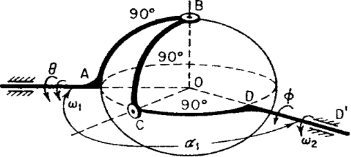
Q7) Write the equations for hooke’s joint?
Ans7) 

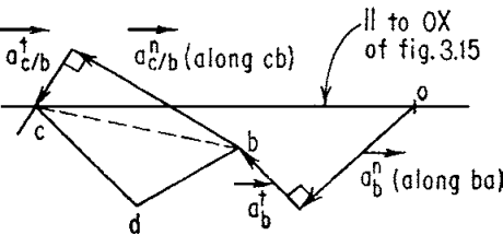
Q8) Draw the acceleration vector diagram?
Ans 8) Now, we can draw the acceleration diagram,
1. Choose an arbitrary origin o, as before.
2. Draw each acceleration of scale ka (inch per inch per second squared), and label the appropriate vector terminals with the lowercase letter corresponding
to the point whose acceleration is designated, e.g., AB = (ob)/ka.
Draw ABn, ABt, Ac/B.

Q9) Explain computer aided analysis of kinematic mechanism?
Ans9) The sort of machine techniques is as giant because the variety of mechanisms. For specific mechanisms, like cams and gears, specialised codes are on the market. In general, pc codes are capable of analysing each straightforward and sophisticated mechanisms. As way as synthesis is bothered the case is difficult by the nonlinearity of the motion parameters in several mechanisms and by the impossibility of limiting most motions to little displacements. For the easier mechanisms synthesis codes ar on the market. For a lot of advanced mechanisms parameter variation of study codes or heuristic ways are in all probability the foremost powerful presently on the market tools. the topic remains underneath intensive development, particularly with reference to interactive lighting tricks [for example, CADSPAM, software of spatial mechanisms. At high speeds the inertia forces related to the moving links cause shaking forces and moments to be transmitted to the frame. equalisation will cut back or eliminate these. Three-dimensional mechanisms also are referred to as “spatial mechanisms.” Points on these mechanisms travel three-dimensional curves. the fundamental three- dimensional mechanisms are the “spherical four-bar mechanisms”.
Q10) Analyse the equation for displacement?
Ans10) Position analysis of a slider-crank mechanism is shown here exploitation analytical methodology. The pure mathematics equations obtained through pure mathematics relationship were solved for unknown joint angles or values. These results enable one to search out the position and therefore the orientation of every link. The language accustomed outline the links and angles is shown in Figure.
