UNIT 3
Kinematic Analysis of Mechanisms: Graphical Method
Q1) Define velocity analysis and relative velocity method?
Ans.1) • Here we tend to shall discuss the appliance of vectors for the relative speed of 2 bodies moving on parallel lines and inclined lines, as shown in Fig.
• Consider 2 bodies A and B moving on parallel lines within the same direction with absolute velocities VA and VB such VA > VB, as shown in Fig. (a). The relative speed of A with relevancy B is …….


Figure.3.1 Relative Velocity Method
Q2) Explain the ICR method?
Ans.2) Velocity of a link by the instantaneous method can be calculated by the following,


Q3) How to calculate velocity by ICV method?
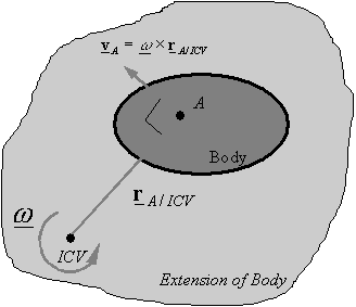
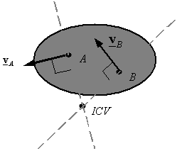
Ans 3): Any point on a rigid body or on its extension that has zero velocity is called the Instantaneous Center of Velocity of the body. Assuming one knows the ICV of a body, one can calculate the velocity of any point A on the body using the equation  and recognizing that be definition
  . This gives,
In the figure, we can easily analyze the instantaneous velocity with respect to the angular velocity.
Q4) What is the method to find ICV?
Ans.4): Given the velocity  of point A on a rigid body and the angular velocity of the rigid body one can use the above equation to find the distance
  between point A and the ICV. One can then draw a line perpendicular to the velocity and passing through A, and move along this line a distance
 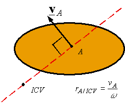 to get to the ICV. The side on which the ICV is can be determined by the direction of the angular velocity.

Figure. ICV Diagram
Given the rate of points A and B on a rigid body one will notice the ICV by drawing a line perpendicular to and spending through A, and by drawing a line perpendicular to and spending through B. one in every of the subsequent 3 cases can result
• The lines run across at one point: the purpose of the intersection is that the ICV. The angular speed may be calculated once the ICV is decided exploitation the rate of either purpose and its corresponding distance from the ICV.
Q5) Write a short note on Kennedy’s theorem?
Ans.5) If 3 bodies have plane motion relative to at least one another, then their area unit 3 instant centers, and therefore the 3 instant centers all lie on the identical line. this can be Kennedy’s theorem.
Using Circle Diagrams for Locating Instant Centers
1. Locate (i.e., identify) primary instant centers. E.G., pin connections, slippery bodies, and rolling bodies with no slippy.
2. Draw a circle and mark equally spaced ticks to represent every link within the mechanism.
3. Draw solid lines distinguishing every of the familiar primary instant centers.
4. Draw broken lines between every purpose (i.e., link) to represent the remaining instant centers to be found.
5. Apply Kennedy's theorem to search out the unknown instant centers.
« Back
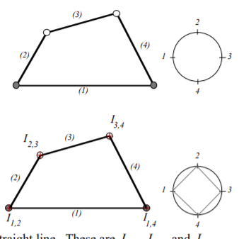
EXAMPLE: Four-bar Linkage
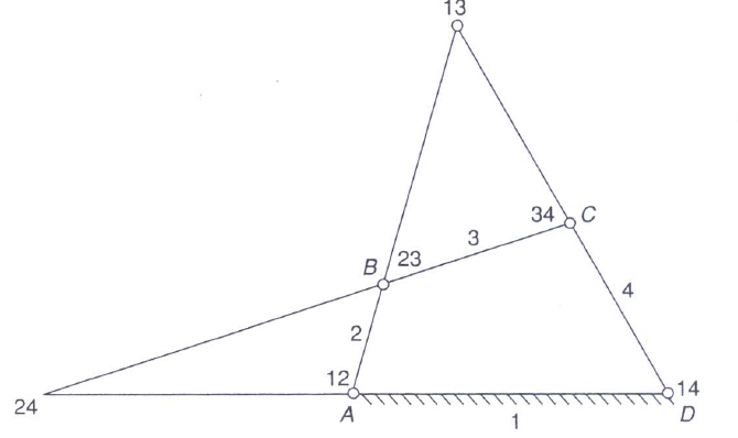
Figure. Four bar Linkage and Circle Diagram
Q6) What is the angular velocity ratio theorem?
Ans.6) When the angular rate of a link is understood and it's needed to search out the angular rate of another link, find their common I-center. the speed of this I-center relative to a hard and fast third link is that the same whether or not the I-center is taken into account on the primary or the second link. First, contemplate the I-center to be thought of on the primary link and procure the speed on the I-center. Then contemplate the I-center to air the second link and realize its angular rate. as an example, if it's needed to search out the angular rate of link four once the angular rate of link two is understood of a four-link mechanism is understood, find the I-center 24. Imagine link two to be within the kind of a flat disc containing purpose 24 and revolving regarding twelve or A.
Then
V24= w2 (24-12)
Now imagine link 4 to be large enough to contain point 24 and revolving about 14 or D. Then
V24= w4 (24-14)
or
W4= 
or
 =
= 
The above equation is known as the angular velocity theorem. In other words, the angular velocity ratio of two links relative to a third link is inversely proportional to the distance of their common I-center from their respective center of rotation. In the above case point, 12 and 14 lie on the same side of 24 on lines 24-14, and the direction of rotation of the two links (2 and 4) is the same i.e clockwise or counterclockwise. Had they been on the opposite side of the common I-center the direction would have been opposite.

Q7) Analyse the mechanism by ICR method?
Ans.7) Instant center of velocities may be a straightforward graphical methodology for activity speed analysis on mechanisms. the strategy provides a visual understanding of however speed vectors are connected. Tools: ruler, right angle, protractor. The instant center of velocities between 2 links is that the location at those 2 coinciding points, one on every link, have identical velocities. The most obvious instant center of velocities, or just the moment center (IC), between 2 links that are fastened to every alternative is that the purpose at the center of the pin joint. for instance, the center of the pin joint between links i and j is viewed as 2 coinciding points, Pi on link i and Pj on link j, that have a similar velocity. the moment center between these 2 links is denoted as ii,j or ii,j . the moment center of velocities might not be settled at intervals the physical boundaries of a link. As shown within the second figure, the IC between links k and h, ik,h, is found on imagined extensions of each link.
Q8) Explain the instant centers for the four-bar mechanism?
Ans.8) A four-bar mechanism has six instant centers despite the scale or orientation of the links. For clerking functions in locating the IC’s, we tend to draw a circle and place link indices on the circle in any desired order. This clerking procedure might not be necessary for a four-bar, however becomes helpful once mechanisms with a larger variety of links area unit thought-about. (1) (2) (3) (4) one a pair of three-four Since pin joints area unit instant centers, for a four-bar with four-pin joints, four IC’s area unit right away known. every found IC is marked on the circle as a line drawn between the 2 corresponding link indices. These four IC’s area units actual (not imaginary) pin joints. so as to seek out the opposite IC’s, we tend to apply Kennedy’s rule. The IC’s between links a pair of, three and four should lie on a line. This area unit I2,3, I3,4, and I2,4. Since we tend to have already got I2,3 and I3,4, we tend to draw a line through them; I2,4 should even be on this line. The IC’s between links one, a pair of and four should lie on a line. This area unit I1,2, I1,4, and I2,4. Since we tend to have already got I1,2 and I1,4, we tend to draw a line through them; I2,4 should even be on this line. The intersection of those 2 lines is I2,4.

Figure. ICR for Four Bar
The number of instantaneous centers in a constrained kinematic chain is equal to the number of possible combinations of two links.

N= 
Q9) Analyse the six -link mechanism?
Ans.9) In this example we consider a six-bar mechanism containing a four-bar and an inverted slider-crank that share one link and one pin joint. A circle is constructed with link indices 1 – 6. We first find the six IC’s that belong to the four-bar.

Figure. Six Link Bar
We first find the six IC’s that belong to the four-bar.

Figure. Analysis of Six Link Mechanism
Q10) Explain the Coriolis component of acceleration?
Ans.10) Coriolis acceleration is generated by the eastward rotation of the earth around the N-S axis.
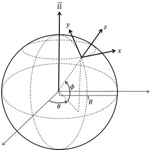
Figure. Definition of x, y, z axes on the rotating earth.
This acceleration will be thought of as a strictly kinematic impact by noting that point derivation in an exceedingly rotating frame introduces a term associated with rotation of the axes of reference [1]:
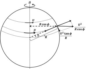
(dr⃗ /dt) mounted +Ω⃗ mounted, where wherever indicates the position of a fluid parcel on the rotating earth (r⃗ =0 at the earth's center), u⃗ ≡dr⃗ /dt is that the rate on the rotating earth, Ω⃗ the rotation vector on the N-S rotation axis. The radial earth rotation frequency Ω≈7.292110−5s−1. The acceleration then follows from (d2r⃗ /dt2) mounted / dt+Ω⃗ mounted +Ω⃗ mounted +Ω⃗ × (Ω⃗ ×r⃗). The term du⃗ /dt is that the acceleration on the rotating earth, 2Ω⃗ ×u⃗ is that the Coriolis acceleration and also the and also the × (Ω⃗ ×r⃗) is the part of the force salaried by earth's attraction and adjustment of the equilibrium ocean surface slope. If no forces area unit functioning on the fluid and within the absence of friction, (d2r⃗ /dt2) mounted frame=0. To seek out a lot of usual formulas for the Coriolis acceleration we have a tendency to use a system of axes on the rotating earth as indicated in figure one, wherever is that the angle indicating meridian (expressed in radians), ϕ the elevation angular unit angle indicating latitude and R is that the earth radius. during this system the vector parts area unit u⃗ = (u=R cosϕ dθ/dt, v=R dϕ /dt,0), Ω⃗ = (0, Ω cosϕ, Ω sinϕ). The Coriolis acceleration is then given by: du/dt=fv, dv/dt=−fu, f=2Ωsinϕ. The Coriolis acceleration will be derived in an exceedingly a lot of intuitive means if we tend to think about fluid velocities (u, v) a lot smaller than the Earth's surface rotation rate U=R Ω cosϕ. because of the rotation of the planet, a force, perpendicular to the earth's rotation axis, acts on ocean waters. This force is just partially salaried by earth's attraction; it's a part acting on the surface of the planet towards the equator, see figure a pair of.
Figure. The tangential component of the centrifugal force.
If water is at rest this tangential component of the centrifugal force is balanced by a sea surface slope. When seawater is brought into motion, this equilibrium is broken and water motion experiences Coriolis acceleration. A current u in east-direction will experience an acceleration toward the equator as a result of the increased tangential component of the centrifugal force:
dv/dt=−sinϕ[(U+u)2−U2]/Rcosϕ≈−fu with f=2Ωsinϕ.
The approximation is very accurate because in natural situations |u|<<|U|.
When fluid is traveling northward along the earth's surface with velocity v=R dϕ/dt, it experiences a decrease of surface rotation velocity U. The principle of angular momentum conservation implies that the fluid will accelerate to conserve its angular momentum. This can be expressed as
d[(U+u) Rcosϕ]/dt=d[ΩR2cos2ϕ+uRcosϕ]/dt=0.
From this equation we find du/dt=fv, assuming again that |u|<<|U|.
When fluid parcels square measure set in motion, they, therefore, expertise associate degree acceleration to the correct on the hemisphere (ϕ>0) associate degreed an acceleration to the left on the hemisphere. as a result of f is tiny (typically on the order of 10-4), the earth's rotation hardly influences currents that fluctuate with higher frequencies, like wave revolution. However, the influence on stationary currents or slowly varied currents, like the wind-driven flow and recurrent event motion, is important (see Coriolis and recurrent event motion in shelf seas). this is often the case in wide basins, with a dimension of the order or larger than |u⃗ +v⃗ |/f. A fluid moving freely (no external or resistance forces) in a very wide basin (no water surface inclination), with initial speed V, can describe a circular motion thanks to Coriolis acceleration: u=V sinft, v=V cosft. The fluid follows an associate degree mechanical phenomenon circle with radius V/f. This flow pattern is typically discovered once a robust watercourse jet enters a good basin.
