UNIT-4
Synthesis of Mechanisms
Q1) Write a note on synthesis of mechanisms?
Ans.1) Kinematic synthesis, additionally called mechanism synthesis, determines the scale and configuration of mechanisms that form the flow of power through a system, or machine, to attain the specified performance. The word synthesis refers to combining elements to make a full. Hartenberg and Denavit describe kinematic synthesis as .it is style, the creation of one thing new. Kinematically, it's the conversion of a motion plan into hardware. Applications of kinematic synthesis embody determining: the topology and dimensions of a linkage system to attain a given task; the size and form of links of a mechanism to maneuver elements and apply forces during a given workspace; the mechanical configuration of end-effectors, or grippers, for robotic systems; the shape of a cam and follower to attain the required output movement coordinated with a specified input movement; the shape of substances teeth to make sure the specified coordination of input and output movement; the configuration of a system of gears, belts, and cable, or rope drives, to perform the specified power transmission; the size and form of fixturing systems to produce exactitude partly manufacture and part assembly Kinematic synthesis for a system is represented as having 3 general phases, called sort synthesis, range synthesis and dimensional synthesis.
Q2) Write a short note on steps in synthesis?
Ans.2) Kinematic synthesis for a system is delineate as having 3 general phases, referred to as type synthesis, number synthesis and dimensional synthesis. sort synthesis matches the final characteristics of a system to the task at hand, choosing from an array of devices like a cam-follower mechanism, linkage, gear train, a fixture or a robotic system to be used in a very needed task. Number synthesis considers the varied ways that a selected device is made, typically focussed on the quantity and options of the elements. Finally, dimensional synthesis determines the pure mathematics and assembly of the elements that type the device.
Type synthesis is that the method of deciding doable mechanism structures to perform a given task or combination of tasks while not relevance the scale of the elements. "The selection of a selected style of mechanism, for instance, the choice of a link mechanism or a cam mechanism." He thought of a separate step, number synthesis, to be "concerned with the selection between mechanisms of identical constructional type, particularly the selection of the number of links and joints." Crossley prompt that within the kind synthesis methodology, "The desired motion is analysed so on realize the only kind (or types) of mechanisms that are capable of manufacturing it, or one thing approximating it." during this definition, "type" is considered to be the "number of constituent members." Type synthesis is approached as 2 freelance steps: topological synthesis--enumerating mechanism structures primarily based only on the topological requirements; and topological analysis--specifying the remaining structural parameters and evaluating each mechanism primarily based only on the purposeful needs. Constraints area unit viewed as enjoying no role in sort synthesis, due to their dependence on dimensions.
He then printed kinematic vary synthesis as "the study of the permutations of a given combination of links and kinematic pairs (joints)," and urged that it might be "better-called synthesis by permutations." He supplementary that it "is applied primarily to linkages having turning joints (pin joints) entirely," noting that "the technique can most promptly be regenerate to accommodate cams, gears, belt drives, hydraulic cylinder mechanisms, and clamping devices," as shown by Hain. Freudenstein and Dobrjansk offered a broader and fewer difficult definition of type synthesis as "the determination of the structure of the mechanism from its [desired] kinematic performance." The "structure" or "topology" of a machine is outlined by the number of links, the amount of and kinds of joints, the property of the links and joints, that links area unit to be thought-about ground and input(s). the strategy of type synthesis is viewed as consisting of two major steps: deciding mechanism structures, and analysing the structures to work out "how well" they'll, once fixing their dimensions, satisfy the look objectives. the primary step, deciding mechanism structures, has been remarked among the literature as selection synthesis, synthesis by permutations, structural synthesis, structural analysis, and others. The second step has usually been remarked as structural analysis. it's the browse of the author's exploitation the term "structural analysis" could be dishonourable, not solely due to thanks to attributable to its ambiguity among the on high of definitions however in addition as a result of its widespread use among the sphere of stress analysis of individual components (structures). so as to avoid confusion, the authors area unit suggesting the use of the terms "topological synthesis" and "topological analysis" to raise these 2 major steps at intervals the type synthesis technique. The procedure consists of 3 steps: downside definition, kind synthesis and dimensional synthesis. The scope of this paper is proscribed to the primary two steps, which might be viewed as a scientific procedure for kind synthesis of mechanisms. The fundamental options of this procedure area unit primarily based on the conception of the separation of structure and function.
Q3) Explain task of synthesis?
Ans.3) If the scale of the mechanism square measure given, and we plan to confirm its motion characteristics, the method is termed analysis. Synthesis is that the inverse method. Given set of performance needs. We plan to proportion a mechanism to satisfy those specification. Synthesis is the procedure by that a product is developed to satisfy a collection of performance needs. There square measure 3 customary tasks for kinematic synthesis: motion, path and performance generation.
Motion generation or rigid body steering
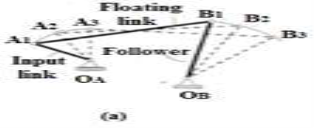
In motion generation (Fig.4.1. a) needs that associate degree entire body be radio-controlled through a prescribed motion sequence. The body to be radio-controlled sometimes may be a a part of "floating link" (not directly connected to the mounted link). The corresponding input (driving) link motion may or might not be prescribed.
Path generation
In path generation (Fig.4.1b) some extent of a floating link is to trace a vicinity outlined with regard to the mounted frame of reference. If the trail points square measure to be correlated with either time or input link positions, the task is termed path generation with prescribed temporal arrangement.
Function generation
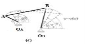
A frequent demand in style is that of causing associate degree output member to rotate, oscillate, or reciprocate in step with a specific operate of your time or operate of the input motion. this can be known as function generation. that's correlation of associate degree input motion with associate degree output motion during a linkage. A simple example is that of synthesizing a four-bar linkage to generate the operate the operate y=f(x). during this case, x would represent the motion (crank angle) of the input crank, and also the linkage would be designed thus that the motion (angle) of the output rocker would approximate the operate y. (Fig. 4.1c) the motions of input and output (driven) link square measure related by the prescribed operate. Since any real mechanism contains a finite number of dimension parameters it is not possible in general to obtain a mathematical exact
solution but that the mechanism match given function, path or body positions at only a finite number of positions called accuracy or precision points. Between these points generated (actual) function Φ(x) deviates from the given (prescribed) mathematical function F(x)
and constraint s 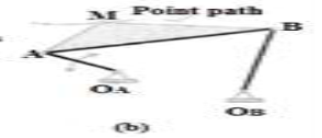
on the cc
of their dependence
Q4) What is precision point?
Ans.4) The precision points are often obtained by the graphical methodology from the subsequent steps:
1. Draw a circle of radius b and centre on the coordinate axis at a distance a from purpose O.
2. Inscribe a daily polygonal shape of facet 2n during this circle specified the 2 sides square measure perpendicular to the coordinate axis.
3. verify the locations of n accuracy points by sticking out the vertices on coordinate axis as shown in Fig.4.2. It is sufficient to draw semi-circles solely showing inscribed polygonal shape to induce the values of precision points.
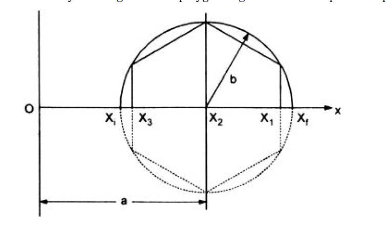 Figure.4.2. Precision points
Q5) What is Chebychev spacing?
Ans.5) Let xi and xj be the initial and final values of variable x respectively. A function f(x) is desired to be generated in the interval xi  x
x  xf. Let the generated function be F (x, R1, R2, …, Rn), where R1, R2, …, Rn are the design parameters. The difference E(x) between the desired function and generated function can be represented by,

At precision points, say for x = x1, x2, …, xn, the desired and generated functions agree and E(x) = 0. At other points E(x) will have some value, called the structural error. It is desirable that E(x) should be minimum. Therefore, the spacing of precision points is very important. The precision points, according to Chebyshevs spacing, are given by:


Q6) What are mechanical and structural errors?
Ans.6) iThere area unit 3 sorts of errors gift within the style of linkages for perform generation. These errors are:
1. Structural,
2. Mechanical, and
3. Graphical.
In perform generation, there's correlation between the motion of input and output links. If the motions of input link is painted as x0, x1, x2, …, xn+1 and therefore the corresponding motions (which depends on input variables x0, x1, …, xn+1) of the output link is painted by y0, y1, y2, …, yn+1, these may be shown on the graph as indicated in Fig.4.1=3. we tend to observe that at sure points (P1, P2, so on) the specified perform and generated perform agree well. These points area unit referred to as exactitude Points. the amount of such points (from three to 6 generally) is adequate the amount of style parameters. Except these points the generated perform curve and desired perform curve don't agree and area unit deviating by certain quantity of error that is understood as Structural Error. Structural error is that the distinction between the generated perform and therefore the desired function for an exact worth of input variable. So, the exactitude points area unit spaced in such how on minimize the structural error of the linkage.
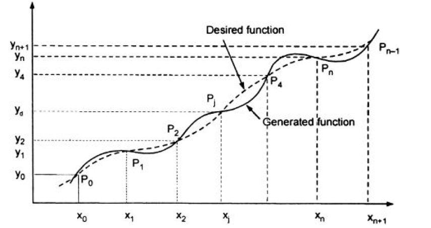
Figure.4.3. Errors in function generation of linkages
Mechanical Errors are caused attributable to mechanical defects like improper machining, casting of components of the linkage, clearance within the elements attributable to rubbing, overloading of linkages, etc.
Graphical Error is caused attributable to quality in drawing of perpendicular or parallel lines. it's going to occur because of wrong graphical construction and wrong alternative of scale. Also, there is also human errors in drawing work.
Q7) Explain graphical method of synthesis?
Ans.7) Graphical synthesis is also accustomed synthesize a four-bar linkage to maneuver a body through 2 such positions at such angles (motion generation). 2 points square measure established within the translated body. A line section is built that connects every point at the 2 such positions. The rotocenter of the body is then found diagrammatically by establishing the conventional bisectors of the two-line segments and distinguishing wherever the conventional bisectors cross (Figure 4.4). 2 fastened pivots is also established anyplace on the two traditional bisectors to outline a four-bar linkage which can move a body through the 2 positions at the prescribed angles. Thus, AN infinite variety of four-bar mechanisms is also outlined that produce an answer. If a pivot is capable of being established at the rotocenter of the body, a rigid body that pivots at the rotocenter is also used as an answer. Graphical synthesis is also accustomed synthesize a four-bar linkage to maneuver a body through 3 such positions at specified angles (motion generation). With 3 positions, the two ground pivot points square measure outlined by the intersection of the conventional bisectors generated between outlined positions one and a pair of and outlined positions three and four (Figure.4.5). If one assumes that; the pivot points within the moving body area unit capable of being placed at any location within the body, there exists associate degree infinite range of ground pivot locations that will be established. Graphical synthesis is also accustomed synthesize a path generation four-bar linkage for 3 prescribed positions (Path Generation). The pivot points Ao and Bo area unit free decisions left to the designer to pick (Figure 4.6). additionally, the length of the drive crank and also the distance from the tip of the drive crank to the trace point is unfair and outlined by the designer. The ground pivots area unit selected and a circle generated concerning the drive crank pivot at the specified length of the bottom pivot. associate degree arc is scribed from the primary prescribed purpose to come across with the scribed drive crank circle. The intersection is one finish of the rod that attaches to the drive crank (Al). This distance Pl-Al is then scribed from P2 and P3 to the drive crank circle (define A2 and A3). The drive crank length is then scribed concerning purpose Al and angles P2- Al-AO and P3-A1-A0 marked concerning Al; AO' and AO'' area unit therefore outlined on the circle scribed concerning Al. associate degree arc is scribed concerning PI with the length of P2-B0 associate degreed an arc is scribed from AO' with the length of AO-BO; the intersection is tagged BO'. associate degree arc is scribed concerning PI with the length of P3-B0 associate degreed an arc is scribed from AO'' with the length of AO-BO; the intersection is tagged BO''. The intersection
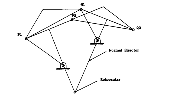 Figure.4.4. Two-point motion generation
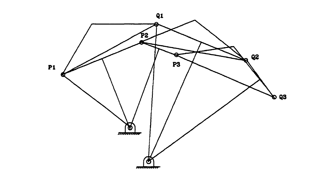
Figure.4.5. Three position motion generation
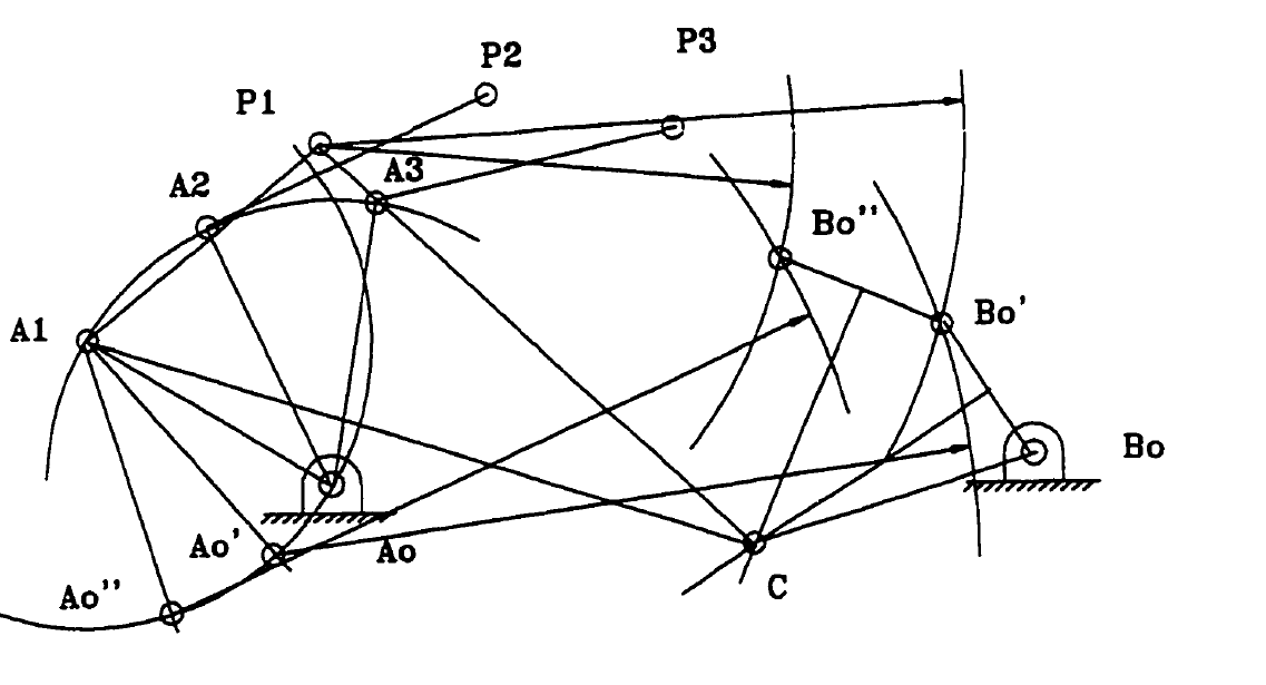
Figure.4.6. Three position path generation
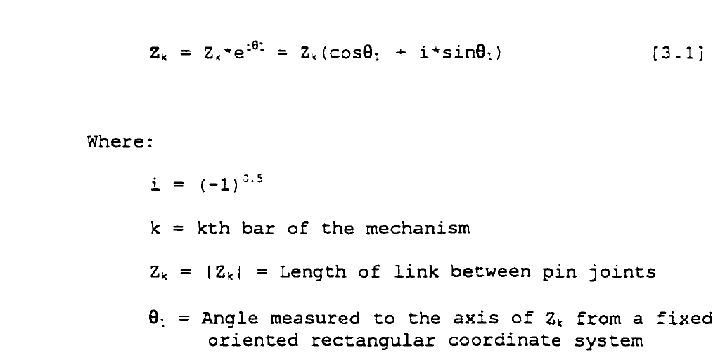
of the perpendicular division of BO-BO' and BO' and BO'' is one finish of the rod. We have mentioned "motion" generation for a body through 2 prescribed positions and 3 prescribed positions and “path" generation for a body through 3 prescribed points. J. Hirschhorn in "Kinematics and Dynamics of Plane Mechanisms" reviews graphical strategies for the synthesis of four-bar mechanisms in depth. Graphical strategies mentioned square measure "motion" generation for a body through four distinct points, "function" generation for a body with up to 5 exactness positions, and "path" generation for a body with up to 6 purpose positions. A graphical "overlay" technique is also mentioned, that could be a trial-and-error procedure for operate generation that yields a generated output based mostly upon a tolerance band throughout the vary of the mechanism; exactness points square measure internet used. Sandor and Erdman detail a graphical procedure for addressing "path" generation with prescribed temporal arrangement for 3 prescribed positions. With regards to "function" generation employing a four-bar linkage, the employment of exactness points defines the position of the mechanism over a spread of the operate. Of interest is that the "structural error", that is that the distinction between the operate generated by the mechanisms and also the desired operate. Chebyshev observed that the simplest linkage approximation to a operate occurs once absolutely the worth of the utmost structural error between exactness points and at the ends of the vary is equalised [Erdman & Sandor. "Chebyshev spacing of exactness points" is a analytical technique accustomed determine the spacing of the exactness points to reduce the structural error. The known exactness points square measure then utilized in a graphical synthesis method for generating the four-bar linkage. Graphical strategies become a lot of complicated to implement because the number of exactness points increase. the method is additionally time consuming once iteration is needed to explore completely different style variables. Analytical Synthesis One category of analytical synthesis depends on complex number modelling of the platelike linkages as vector pairs known as Dyads. Loop closure equations square measure derived by summing the vectors round the mechanism and by shaping displacement vectors to prescribed positions the mechanism should go through. like the graphical method, one downside within the generation of an answer is predicated upon a set variety of given points that square measure a part of the required mechanical device path. reckoning on the quantity of prescribed positions, a series of equations is generated that has got to be at the same time glad to reach an answer. because the variety of prescribed positions will increase, the designer is allowed fewer selections with regards to attributes of the four-bar linkage (e.g., mounting location, link angles, link length, etc). Closed type solutions will effectively be self-addressed for up to four exactness points and solutions is also obtained for five exactness points. for 6 up to 9 exactness points, nonlinear equations should be solved. Numerical strategies, like Newton- Raphson, square measure used for the a lot of complicated mechanisms that don't have closed type solutions. Numerical strategies used for exactness purpose synthesis of mechanisms have 2 key limitations: 1) Convergence needs a comparatively shut estimate of a mechanism for the solutions, 2) Numerical strategies converge to one resolution that depends on the initial estimate and doesn't generate all the possible styles that satisfy the constraint equations. An analytical model of a four-bar mechanism provides the capability to use mathematical techniques for synthesis of mechanisms. Sandor and Erdman apply complex-numbers as a tool for modeling linkage members of the four-bar mechanism. Each link within the mechanism is outlined by a relative position vector Z and is expressed as a posh variety. the primary position of a link may be written:
The four-bar mechanism could also be viewed analytically as a mixture of vector pairs, or dyads, that once additional along type a closed-loop system (Figure 4.7). Adding every of the link vectors along forms a loop closure equation:
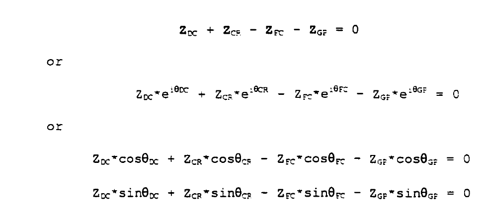

Figure.4.7. Dyads forming a closed loop
Q8) What is freudenstien equation?
Ans.8) Consider a four-bar mechanism as shown in Fig.4.8. in equilibrium. The magnitudes of AB, BC, CD and DA are a, b, c and d severally. θ, β and ϕ area unit the angles of AB, B.C. and DC severally with the coordinate axis. AD is the fixed link. AB is that the input link and DC the output link. The displacement on coordinate axis is, a cos θ + b cos β = d + c cos ϕ

The displacement along y-axis is,
a sin θ + b sin β = c sin ϕ
or
b sin β = c sin ϕ − a sin θ

Adding Eqs. (1) and (2), we get,
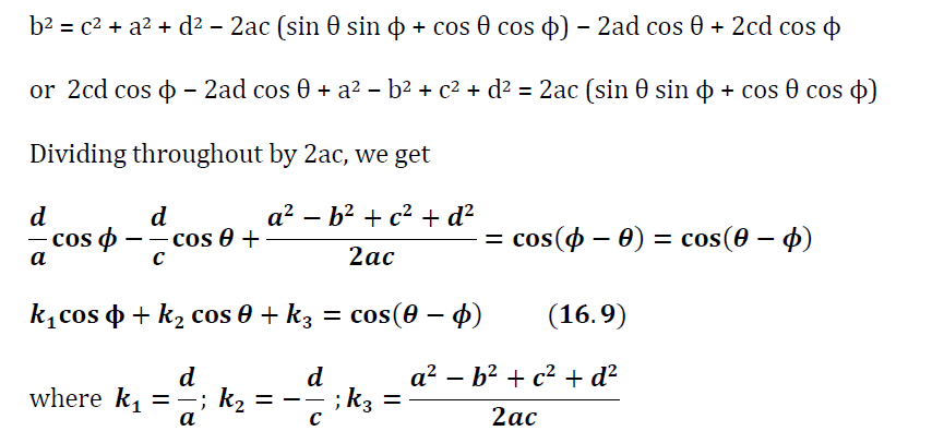 Equation above (16.9) named as Freudenstein equation.
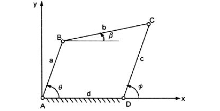
Figure.4.8. Freudenstein’s Equation
Q9) What is freudenstien’s equation for precision points?
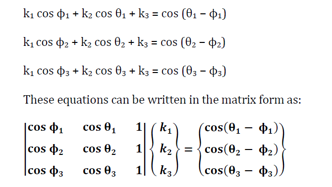
Ans.9) Freudensteins equation helps to determine the length of links of a four-bar mechanism. The displacement equation of a four-bar mechanism, shown in Fig.4.9 is given by:

Equation above is freudenstein’s equation.
Let the input and output are related by some function, such as, y = f(x).
For three specified positions, let
θ1, θ2, θ3 = three positions of input link
ϕ1, ϕ2, ϕ3 = three positions of output link
Above equation can be written in form as:
Q10) What is blotch synthesis?
Ans.10) A special reasonably linkage synthesis happens once input-output relations aren't such at 3 distinct values of the input and output angles, however rather at one single worth of these angles, to that speed and acceleration conditions are adjoined. the matter thus arising is thought as Ernest Bloch synthesis. Besides its special nature, this drawback becomes relevant owing to its revelation:
The coinciding vanishing of speed and acceleration of the output link, i.e., second-order remainder of the output link, cannot be obtained with a coplanar four-bar linkage whose input link turns at a continuing angular speed. The preceding claim are created clear within the sequel. As a matter of truth, second-order rest cannot
be obtained with any linkage, however smart approximations are often obtained with six-bar linkages manufacturing short-duration dwell.
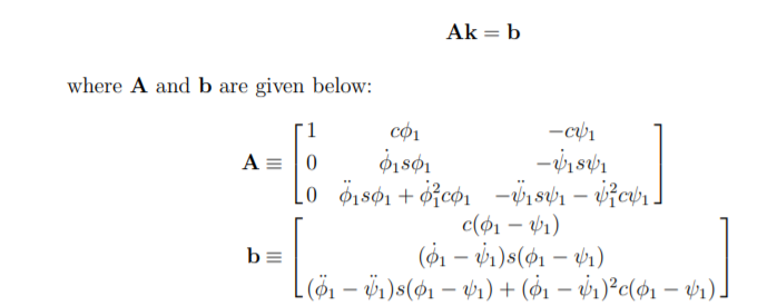
The problem at hand then may be expressed as: Synthesize a four-bar linkage that meets conditions on position, speed and acceleration at a given position of the input link. so as to formulate this drawback, we tend to differentiate each side of the Freudenstein equation, with regard to time. once the arrangement of terms and a reversal of signs, this gives

Next, we write the above equations in vector form:
