UNIT-5
Kinematics of Gears
Q1) Define pitch circle?
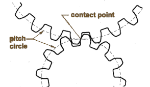
Ans1) A circle radius of which is equal to the distance from the gear axis to the pitch point. It is the imaginary circle that rolls without slipping with a pitch circle of a mating gear. These are the outlines off the imaginary smooth roller or friction discs in every pair of mating gears. Many important measurements are taken on and from this circle. Pitch circle is shown in Fig. 1.
Q2) Define pressure angle?
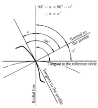
Ans 2) The pressure angle exists between the tooth profile and a radial line to its pitch point. In involute teeth, it is defined as the angle formed by the radial line and the line tangent to the profile at the pitch point.
Q3) Classify the gears?
Ans 3) The types of gears are:
(a) Parallel
(b) Intersecting
(c) Non-intersecting and Non-parallel
2. According to peripheral velocity of the gears:
(a) Low Velocity
(b) Medium Velocity
(c) High Velocity
3. According to the type of gearing:
(a) External gearing
(b) Internal gearing
(c) Rack and Pinion
4. According to position of teeth on Gear Surface
(a) Straight
(b) Inclined
(c) Curved
1 (a) Parallel Gears: The two parallel and two-dimensional shafts connected by the gears. These gears area unit known as spur gears and also the arrangement is thought as spur geartrain. These gears have teeth parallel to the axis of the wheel. once the teeth area unit inclined to the axis then they're called voluted gears.
(b) Intersecting shafts: The two non-parallel or across two-dimensional shafts connected by gears is shown in figure.5.3. These gears area unit known as bevel gears and arrangement is understood as bevel power train. The bevel gears like spur gears might have conjointly teeth inclined to the face of bevel within which case they're called whorled bevel gears. this kind of power train is additionally called whorled bevel gears.
(c) The two non-intersecting and non-parallel shafts i.e., non-coplanar shafts connected by gears is shown in figure.5.3. These gears square measure skew bevel or spiral gears and therefore the arrangement is thought as skew bevel or spiral gears and arrangement is thought as skew bevel or spiral gears.
2) The gears having rate but three m/s square measure referred to as low-rate gears and gears having rate between three and fifteen m/s square measure referred to as medium rate gears. If the speed of gears is quite fifteen m/s then these square measures referred to as high-speed gears.
3. In external geartrain, the gear of the 2 shafts mesh outwardly with one another. The larger of those 2 wheels is spur gear and smaller one is thought as pinion. In associate degree external geartrain motion of the 2 wheels is usually not like. In internal geartrain, the gear of the 2 shafts mesh internally with one another. The larger of those 2 wheels is termed ring-shaped wheel and smaller wheel is termed pinion. Motion of the wheels is like in these forms of shafts.
4. According to position of teeth surface gears square measure classified as straight, curving or inclined.
Q4) What are gears and gear trains?
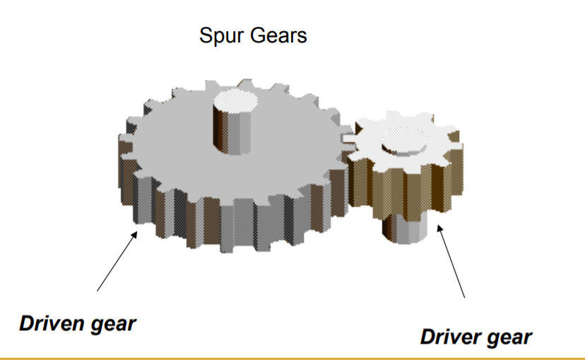
Ans 4) Gears are most often used in transmissions to convert an electric motor’s high speed and low torque to a shaft’s requirements for low speed high torque: Speed is easy to generate, because voltage is easy to generate Torque is difficult to generate because it requires large amounts of current Gears essentially allow positive engagement between teeth so high forces can be transmitted while still undergoing essentially rolling contact Gears do not depend on friction and do best when friction is minimized. Example of spur gear shown below:
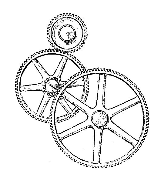
A gear train is a mechanical system formed by mounting gears on a frame so the teeth of the gears engage. Features of gears and gear trains include:
Q5) Define law of gearing?
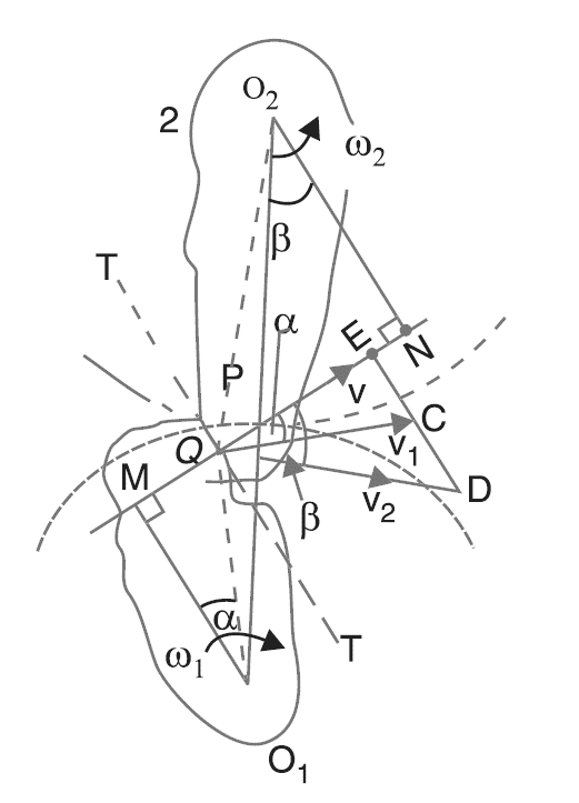
Ans 5) Consider the parts of the 2 teeth, one on the wheel one (or pinion) and therefore the alternative on the wheel two. Let the 2 teeth are available in contact at purpose alphabetic character, and therefore the wheels rotate within the directions as shown within the figure. Let T T be the common tangent and MN be the common traditional to the curves at the purpose of contact alphabetic character. From the centres O1 and O2, draw O1M and O2N perpendicular to MN. a bit thought can show that the purpose alphabetic character moves within the direction QC, once thought of as some extent on wheel one, and within the direction QD once thought of as some extent on wheel two. Let v1 and v2 be the velocities of the purpose alphabetic character on the wheels one and a pair of severally. If the teeth area unit to stay up-to-date, then the elements of those velocities on the common traditional MN should be equal.
Q6) Explain with the help of diagram cycloidal and involute profiles?
Ans6) A cycloid may be a curve derived by some extent on the circumference of a circle that rolls while not slippy on the skin of a hard and fast circle, the curve derived by some extent on the circumference of a circle is understood as epi-cycloid. On the opposite hand, if a circle rolls while not slippy on the within of a hard and fast circle, then the curve derived by some extent on the circumference of a circle is understood as hypo-cycloid. The gear tooth that traces cycloid curve on its paring gear is alleged to own a rounded profile.

Figure.5.4. Cycloidal Profile
Types of cycloidal profile: -
1. Epicycloidal profile
2. Hypocycloidal profile
1. Elicycloidal profile:
If the circle rolls without slipping outside the base circle the curve traced by point on the circumference is called “epicycloid” and profile is said as “epicycloidal profile”.
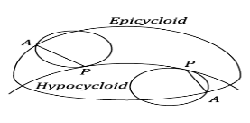
Figure.5.5 Epicycloid and Hypocycloid
2. Hypocycloidal profile:
If a circle rolls without slipping inside the base circle the curve traced by the point on the circumference of the base circle is known as ‘hypocycloid’ and the profile is known as ‘hypocycloidal profile’.
Involute Profile
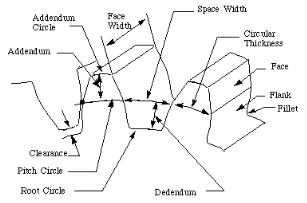
Figure.5.5. Involute Profile
Q7) What is gear ratio and train ratio in a gear train?
Ans 7) The gear ratio is:

The train value is:

As shown in figure we can easily find out the train value and gear ratio in a gear train.
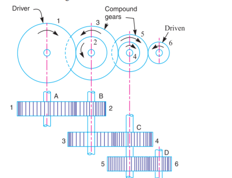
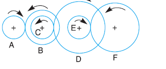
Q8) The gearing of a machine tool is shown in Fig. The motor shaft is connected to gear A and rotates at 975 r.p.m. The gear wheels B, C, D and E are fixed to parallel shafts rotating together. The final gear F is fixed on the output
shaft. What is the speed of gear F? The number of teeth on each gear are as given below:

Ans 8) Given: NA = 975 r.p.m.;
TA = 20; TB = 50; TC = 25; TD = 75; TE = 26; TF = 65
From Fig. 13.3, we see that gears A, C and E are drivers while the gears B, D and F are driven or followers. Let the gear A rotates in clockwise direction. Since the gears B and C are mounted on the same shaft, therefore it is a compound gear and the direction or rotation of both these gears is same (i.e., anticlockwise).
Similarly, the gears D and E are mounted on the same shaft, therefore it is also a compound gear and the direction of rotation of both these gears is same (i.e., clockwise). The gear F will rotate in anticlockwise direction.
Let NF = Speed of gear F, i.e., last driven or follower.
We know that,


Q9) Define Epicyclic Gear train?
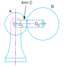
Ans9) A simple epicyclic gear train is shown, where a gear A and the arm C have a common axis at O1 about which they can rotate. The gear B meshes with gear A and has its axis on the arm at O2, about which the gear B can rotate. If the arm is fixed, the gear train is simple and gear A can drive gear B or vice- versa, but if gear A is fixed and the arm is rotated about the axis of gear A (i.e. O1), then the gear B is forced to rotate upon and around gear A. Such a motion is called epicyclic and the gear trains arranged in such a manner that one or more of
their members move upon and around another member are known as epicyclic gear trains (epi. means upon and cyclic means around). The epicyclic gear trains may be simple or compound. The epicyclic gear trains are useful for transmitting
high velocity ratios with gears of moderate size in a comparatively lesser space. The epicyclic gear trains are used in the back gear of lathe, differential gears of the automobiles, hoists, pulley blocks, wrist watches etc.
Q10) Analyse holding torque in a gear train?
Ans 10 )
Holding torque - simple, compound and Epicyclic gear Trains When the rotating parts of an epicyclic gear train, as shown in Fig.5.26, have no angular acceleration, the gear train is kept in equilibrium by the three externally applied torques, viz. 1. Input torque on the driving member (T1), 2. Output torque or resisting or load torque on the driven member (T2), 3. Holding or braking or fixing torque on the fixed member (T3). |
The net torque applied to the gear train must be zero. In other words,
T1 + T2 + T3 = 0 ...(i)
∴ F1 .r1 + F2.r2 + F3.r3 = 0 ..(ii)
where F1, F2 and F3 are the corresponding externally applied forces at radii r1, r2 and r3. Further, if ω1, ω2 and ω3 are the angular speeds of the driving, driven and fixed members respectively, and the friction be neglected, then the net kinetic energy dissipated by the gear train must be zero, i.e.
T1.ω1 + T2.ω2 + T3.ω3 = 0 ...(iii)
But, for a fixed member, ω3 = 0 ∴ T1.ω1 + T2.ω2 = 0