Unit - 3
Sheet Metal Forming
Q1) Explain any 3 types of Sheet metal operation.
A1) 1. Shearing
It is a cut in a straight line across a strip, sheet or bar. It leaves a lean edge on the piece of metal is sheared or cut. In this operation, a sheet metal workpiece is placed or kept between two dies from one end. And, the punch is hit at the other end of the sheet, producing a shearing effect.
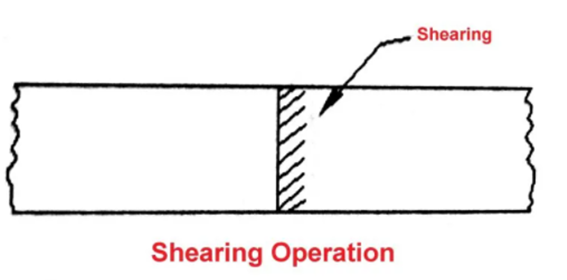
It has 3 basic stages:
a) Plastic Deformation
When a metal is placed between the upper and lower blades of the shear and pressure is applied, plastic deformation takes place. It extends into metal for about 5 to 40% of metal thickness.
b) Fracture
At the point of greatest stress concentration fracture takes place.
c) Shear
Small fractures are found and the metal is sheared.
2. Blanking

It is an operation of cutting a whole piece from sheet metal. In which enough scrap is left all around as shown in fig. A punch and die is applied for this type of sheet metal operation.
3. Punching
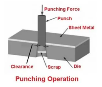
It is an operation of producing circular holes on a sheet of metal by a punch and die. This is the exact opposite of blanking but the operation is nearly the same. A Punch and die are further used here such as blanking operations.
Q2) Explain any 3 types of Sheet metal operation.
A2)
1. Piercing
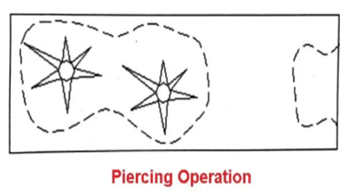
Piercing is the process in which desired shape holes are produced in a piece of sheet metal without eliminating any material from the sheet or removing a very small amount of material as shown in the figure. Both punch and die are also applied in this operation. The punch used in the piercing operation is usually bullet-shaped.
2. Trimming
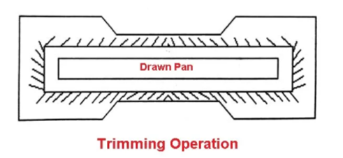
The trimming operation is also known as shaving operation. It is a finishing operation by removing the burrs from the cut edges is taken out in order to make edges smooth and also provide dimensional accuracy.
3. Drawing
It is an operation of producing thin-walled hallows or vessel shaped parts from sheet metal. It can be divided into two categories:

a) Deep Drawing
The length of depth of the object to be drawn is deeper than its width.
b) Shallow Drawing
The length of the object to be drawn is less than its width. The examples of drawing are pans, tubes and cams.
Q3) Explain any 3 types of Sheet metal operation.
A3) 1. Embossing

It is the metalworking operation which is used to create raised surfaces or lettering in sheet metal. There is no change in metal thickness during this operation.
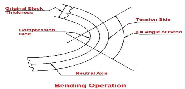
2. Bending
It occurs when forces are applied to localized areas. Here the metal flow is uniform along the bend axis with the inner surface in compression and outer surface in tension.
3. Squeezing
It is a quick and widely used way of forming ductile metals. It has different operations such as sizing, coining, riveting etc.
1. Sizing
Sizing operation is a squeezing operation that reduces the thickness of the metal. The sizing is done in an open die and only the surface where the die and workpiece touch will be sized.
2. Coining
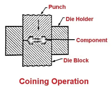
It is a process of pressing metal in a die so that it flows into the die space. For example, Medals, Coins, and Jewellery.
Q4) Explain Press working terminology.
A4)
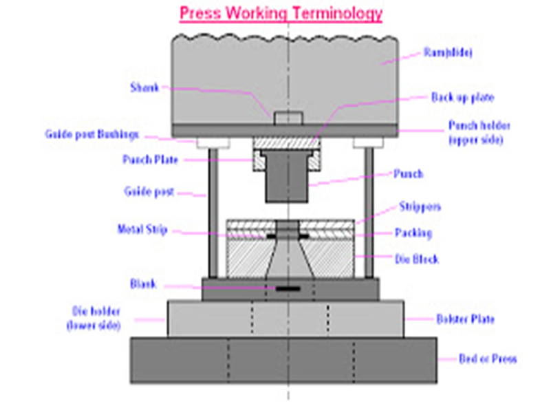
1: Bed:
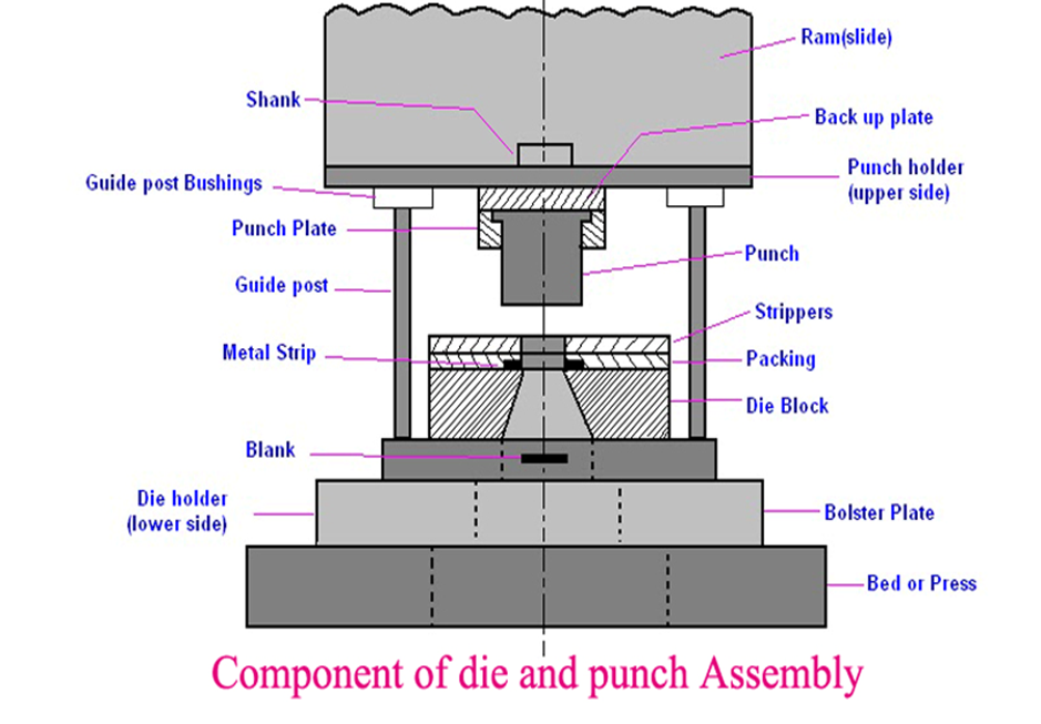
The bed is the lower part of the press frame that serves as a table to which a Bolster plate is mounted.
2: Bolster Plate:
This is a thick plate secured to the press bed, which is used for locating and supporting the die assembly. It is usually 5 to 12.5 cm thick.
3: Die Set:
It is unit assembly which incorporates a lower and upper shoe, two or more guide parts and guide part bushings.
4: Die Block:
It is a block or a plate which contains a die cavity
5: Lower Shoe:
The lower shoe of a die set is generally mounted on the bolster plate of a press. The die block is mounted on the lower shoe, also the guide post is mounted on it.
6: Punch:
This is male component of a die assembly, which is directly or indirectly moved by and fastened to the press ram or slide.
7: Upper Shoe:
This is the upper part of the die set which contains guide post bushings.
8: Punch Plate:
The punch plate or punch retainer fits closely over the body of the punch and holds it in proper relative position.
9: Back up Plate:
Back up plate or pressure plate is placed so that intensity of pressure does not become excessive on punch holder. The plate distributes the pressure over a wide area and the intensity of pressure on the punch holder is reduced to avoid crushing.
10: Stripper:
It is a plate which is used to strip the metal strip from cutting a non-cutting Punch or die. It may also guide the sheet.
Q5) Explain dies and types of dies.
A5) Die:
The die may be defined as the female part of a complete tool for producing work in a press. It is also referred to a complete tool consists of a pair of mating members for producing work in a press.
Types of dies:
The dies may be classified according to the type of press operation and according to the method of operation.
(A): According to type of press operation:
According to this criterion, the dies may be classified as cutting dies and forming dies.
1: Cutting Dies:
These dies are used to cut the metal. They utilize the cutting or shearing action. The common cutting dies are: blanking dies, perforating dies, notching dies, trimming, shaving and nibbling dies.
2: Forming Dies:
These dies change the appearance of the blank without removing any stock. Theses dies include bending, drawing and squeezing dies etc.
(B) According to the method of operation:
According to this criterion, the dies may be classified as: single operation or simple dies, compound dies, combination dies, progressive dies, transfer dies and multiple dies.
Q6) Explain types of dies in detail.
A6) 1: Simple Dies:
Simple dies or single action dies perform single operation for each stroke of the press slide. The operation may be one of the operations listed under cutting or forming dies.
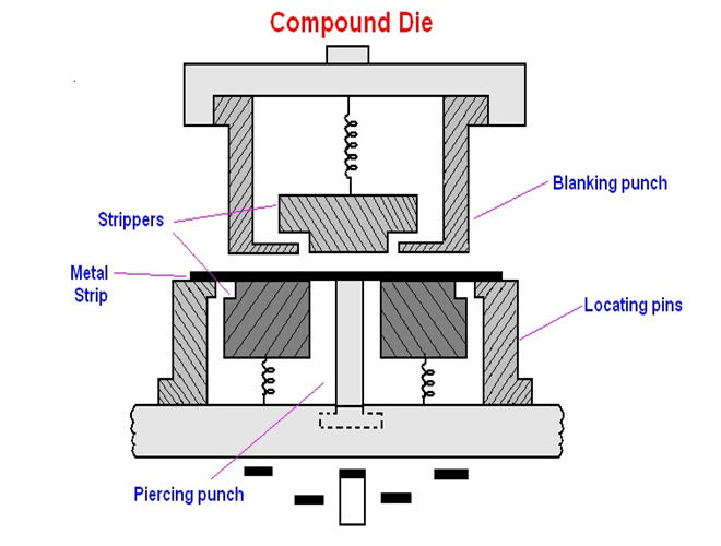
2: Compound Dies:
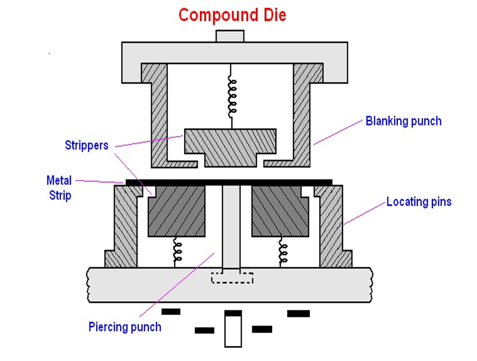
In these dies, two or more operations may be performed at one station. Such dies are considered as cutting tools since, only cutting operations are carried out. Figure shows a simple compound die in which a washer is made by one stroke of the press. The washer is produced by simulation blanking and piercing operations. Compound dies are more accurate and economical in production as compared to single operation dies.
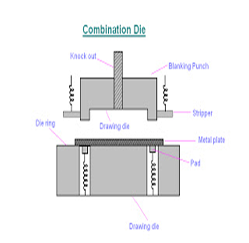
3: Combination Dies:
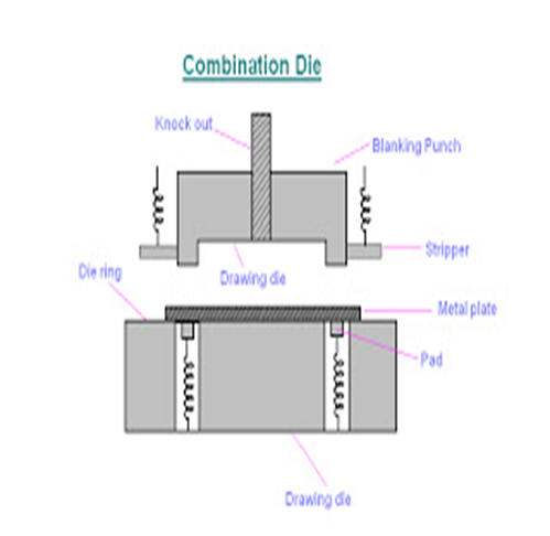
In this die also, more than one operation may be performed at one station. It is difficult from compound die in that in this die, a cutting operation is combined with a bending or drawing operation, due to that it is called combination die.
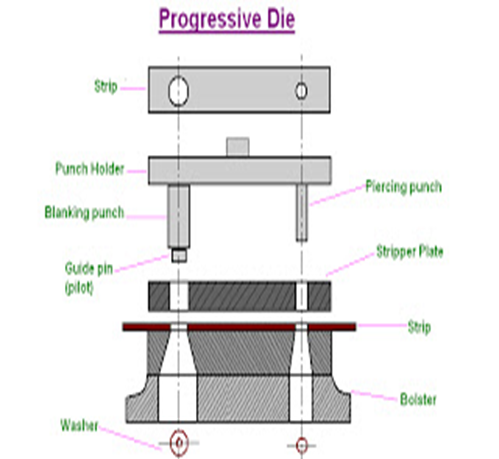
4: Progressive Dies:
A progressive or follow-on die has a series of operations. At each station, an operation is performed on a work piece during a stroke of the press. Between stroke the piece in the metal strip is transferred to the next station. A finished work piece is made at each stroke of the press. While the piercing punch cuts a hole in the stroke, the blanking punch blanks out a portion of the metal in which a hole had been pierced at a previous station. Thus, after the first stroke, when only a hole will be punched, each stroke of the press produces a finished washer.
6: Transfer Dies:
Unlike the progressive dies where the stroke is fed progressively from one station to another. In transfer dies the already cut blanks are fed mechanically from one station to other station.
7: Multiple Dies:
Multiple or gang dies produce two or more work piece at each stroke of the press. A gang or number of simple dies and punches are ganged together to produced two or more parts at each stoke of the press.
Q7) Explain Clearance analysis.
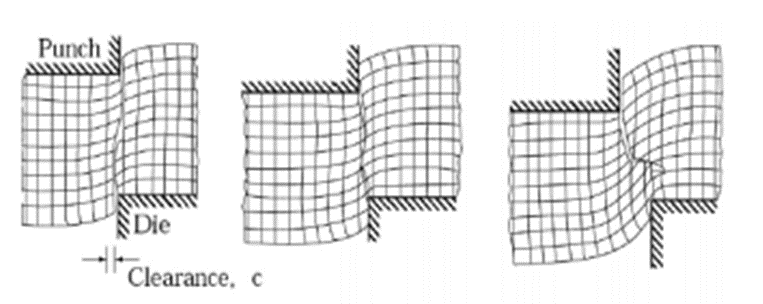
A7) Clearance is the difference in size between punch and dies in a series of punching processes, measured from one side. The difference in size may vary due to punches and dies having a maximum and minimum size, which means that there are differences in the size of one punch or dies.
The amount of clearance in a process of punching ranges between 5% - 7.5% of the thickness of the material being cut. If the clearance is too small (about 3%) it can cause a tear in the material being cut. If the clearance is too large (above 10%) it can cause burr / fracture the tip.
A punch and die set can be round, square, triangular, slot shaped or in another particular shape. Punch and dies have a certain size with a certain tolerance. Good clearance is a difference in size that allows the best result from the punching process.
The effects of clearance on the cutting process include: = the magnitude of the cutting force required. = the lifespan of the punch as the upper cutting tool. = the lifespan of the dies as the lower cutting tool. = the smoothness of the resulting surface / surface finish.
Q8) Explain estimation of cutting forces in sheet metal forming.
A8) Cutting force: -
It is the force required to cut the material or separate out from the parent material. This force is required to cut out the blank or slug from the stock material.
This shearing force is used to calculate the press tonnage for the force: - tool.
Calculation of cutting force: -
The magnitude of cutting force which is also called shearing force is depends upon the area to be cut and mechanical properties of stock material. The force required to shear the blank or slug is calculated by following formula: -
Fsh = l x t x T max
Where,
Fsh = shearing force in Newton
l = length of cut/ perimeter of the component in mm
t = thickness of sheet/ stock material in mm
T max = ultimate shear strength of stock material N/mm^2.
Press tonnage: -
The minimum capacity of press for particular tool is determined as: -
Press tonnage (min.) = cutting force + 20% of cutting force
or simply
Press tonnage = 1.2 x Fsh (tonne)
The cutting force calculated by the above formula is calculated in newton, for application it is converted into tonne by dividing it 9810 (or 10000 for easy calculation.)
Methods of reducing cutting force: -
When the punch moves downward and penetrates the stock material, the material is subjected to tensile and compressive forces and the stresses are highest at the edge of the punch and die. A sufficient amount of force is required to shear the stock material. Sometimes our presses go overloading, to prevent this we need to reduces the cutting force. If we slightly change in the design of punch and die, we can reduce these stresses and the force required to cut.
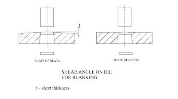
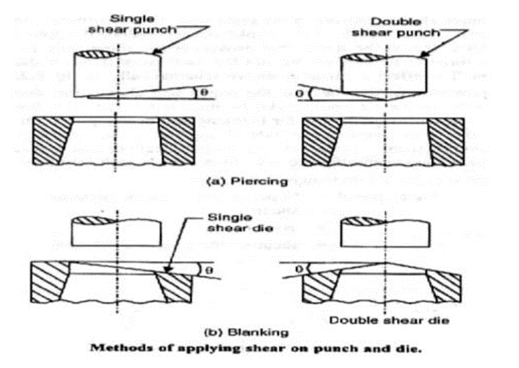
A method to reduce cutting force is to shear the working face of punch or die at a small shear angle with respect to horizontal plane. By applying the shear angle, the contact area is reduced during shearing at any one time. The longest portion of punch or die is cut first and then the rest of the tool is follow it.
Shear the punch or die towards the center from all sides (double shear angle) is generally preferred over the single shear angle. Because in single shear angle, the shearing process is not centralized around the tool axis. It is shifted away from the center of the tool and create lateral force.
The change in punch length by applying the shear angle should be 1 to 1.5 times of sheet thickness.
Q9) Explain center of pressure in sheet metal forming.
A9) CENTRE OF PRESSURE
When the shape of blank to be cut is irregular, the summation of shear forces about the center line of press ram may not be symmetrical. Due to this, bending moments will be introduced in the press ram, producing misalignment and undesirable deflections.
To avoid this the “center of pressure” of the shearing action of the die must be found and while laying out the punch position on the punch holder, it should be ensured that the center line of press ram passes exactly through the center of pressure of the blank. This “center of pressure” is the centroid of the line perimeter of the blank. It should be noted that it is not the centroid of the area of the blank.
The center of pressure can be found out by the following procedure: -
1.An outline of the piece part is drawn.
2.The X and Y axes are placed on it in a convenient position.
3.The outline of the piece part is divided into convenient line elements. These are numbered as 1,2,3 and so on.
4.The lengths l1, l2, l3 etc. of these line elements are determined.
5.The centroids of these line elements are determined.
6.The distance of the centroids from the X and Y axes is determined. Let x1, x2, x3etc. and y1, y2, y3 etc. be the distance of centroids of line elements l1, l2, l3 etc., from the X and Y axes respectively.
7.The distance of the center of pressure from each axis is determined by the method of centroids. i.e.,
X =l1x1+l2x2+l3x3+………/l1+l2+l3+……………….
And
Y = l1y1+l2y2+l3y3+……/ l1+l2+l3+…………….
Where,
X = x distance to center of pressure
Y = y distance to center of pressure
Example for how to calculate center of pressure
All dimensions are in cm
Elements l x y lx ly
1 10 5 0 50 0
2 1.25 10 0.625 12.5 0.781
3 6.25 6.875 1.25 42.969 7.813
4 7.5 3.75 5 28.125 37.5
5 1.25 3.125 8.75 3.906 10.937
6 7.5 2.5 5 18.75 37.5
7 2.5 1.25 1.25 3.125 3.125
8 1.25 0 0.625 0 0.781
--------------- ----------- -----------
37.5 159.375 98.437
∑l = 37.5
∑lx = 159.375
∑ly = 98.437
Therefore, X = ∑lx/∑l = 159.375/37.5 = 4.25
Y = ∑ly/∑l = 98.437/37.5 = 2.625
blank size determination
Q10) Explain the Design of strip lay-out.
A10) Strip-layout design is an important step in the planning stage of sheet metal work on progressive die. It is an experience-driven activity and the quality of strip-layout is highly dependent on the knowledge and skill of die designers. This paper presents an expert system for automation of strip-layout design process. The proposed system is developed using the production rule-based expert system approach of Artificial Intelligence (AI). It comprises six modules to impart expert advices to the user for identifying sheet metal operations, sequencing of operations, selection of proper piloting scheme, number of stations, staging of operations on progressive die and selection of proper dimensions of stock strip. Finally, the system models the strip-layout automatically in the drawing editor of AutoCAD using the output data files of other modules. Usefulness of the system is demonstrated through an example of an industrial component. The system is flexible and has low cost of implementation.
Q11) Explain Blanking die design.
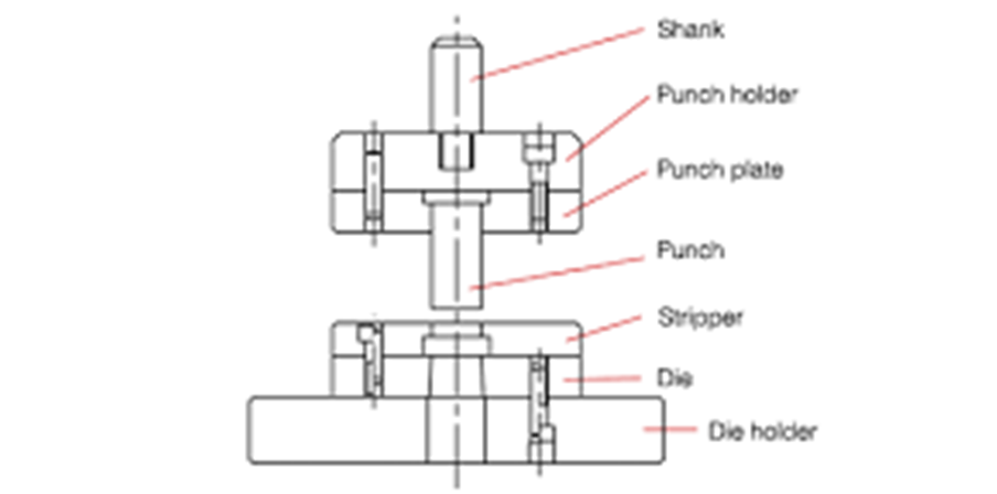
A11) Nearly all of the preceding press working operations are performed with conventional punch-and-die tooling. The tooling is referred to as a die. It is custom- designed for the particular part to be produced. The term stamping die is sometimes used for high production dies.
Q12) What is drawing? Explain 1 type of drawing.
A12) DRAWING
Drawing is the process of forming a flat piece of material i.e., blank into a hollow shape by means of a punch which causes the blank to flow into die cavity. Drawing is classified as shallow, moderate or deep as following: Shallow h/d < ½ Moderate ½ < h/d < 1 Deep h/d > 1 It is a process of cold forming a flat blank of sheet metal into a hollow vessel without much wrinkling, trimming, or fracturing. The process involves forcing the sheet metal blank into a die cavity with a punch. The punch exerts sufficient force and the metal is drawn over the edge of the die opening and into the die, Fig 6.4. In forming a cup, however, the metal goes completely into the die, The metal being drawn must possess a combination of ductility and strength so that it does not rupture in the critical area (where the metal blends from the punch face to the vertical portion of the punch). The metal in this area is subjected to stress that occurs when the metal is pulled from the flat blank into the die.
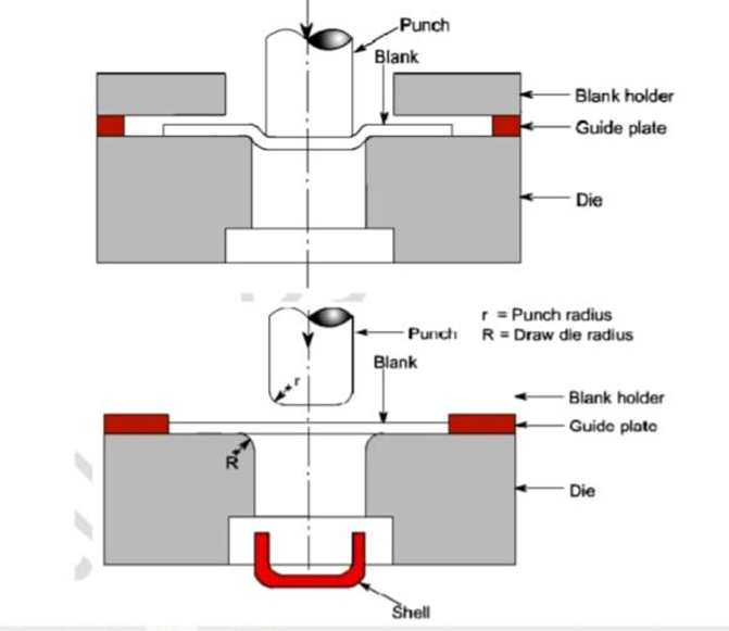
Drawing is a metalworking process which uses tensile forces to stretch metal. As the metal is drawn (pulled), it stretches thinner, into a desired shape and thickness. Drawing is classified in two types: sheet metal drawing and wire, bar, and tube drawing. The specific definition for sheet metal drawing is that it involves plastic deformation over a curved axis. For wire, bar, and tube drawing the starting stock is drawn through a die to reduce its diameter and increase its length. Drawing is usually done at room temperature, thus classified a cold working process, however it may be performed at elevated temperatures to hot work large wires, rods or hollow sections in order to reduce forces. DRAWING IS ONE TYPE OF EXTRUSION Drawing differs from rolling in that the pressure of drawing is not transmitted through the turning action of the mill but instead depends on force applied locally near the area of compression. This means the amount of possible drawing force is limited by the tensile strength of the material, a fact that is particularly evident when drawing thin wires.
DEEP DRAWING
Sheet metal drawing becomes deep drawing when the work piece is drawing longer than its diameter. It is common that the work piece is also processed using other forming processes, such as piercing, ironing, necking, rolling, and beading.
Q13) Explain types of Drawing.
A13) DEEP DRAWING
Sheet metal drawing becomes deep drawing when the work piece is drawing longer than its diameter. It is common that the work piece is also processed using other forming processes, such as piercing, ironing, necking, rolling, and beading.
BAR DRAWING
Bars or rods that are drawn cannot be coiled therefore straight-pull draw benches are used. Chain drives are used to draw work pieces up to 30 m (98 ft). Hydraulic cylinders are used for shorter length work pieces. The reduction in area is usually restricted to between 20 and 50%, because greater reductions would exceed the tensile strength of the material, depending on its ductility. To achieve a certain size or shape multiple passes through progressively smaller dies or intermediate anneals may be required.
COLD DRAWING PROCESS DRAWING
In this process, the material being drawn is at room temperature (i.e., Cold-Drawn). The pointed/reduced end of the bar or coil, which is smaller than the die opening, is passed through the die where it enters a gripping device of the drawing machine. The drawing machine pulls or draws the remaining unreduced section of the bar or coil through the die. The die reduces the cross section of the original bar or coil, shapes the profile of the product and increases the length of the original product
TUBE DRAWING
Tube drawing is very similar to bar drawing, except the beginning stock is a tube. It is used to decrease the diameter, improve surface finish and improve dimensional accuracy. A mandrel may or may not be used depending on the specific process used.
WIRE DRAWING
This technique has long been used to produce flexible metal wire by drawing the material through a series of dies of decreasing size. These dies are manufactured from a number of materials, the most common being tungsten carbide and diamond.
PLASTIC DRAWING
Plastic drawing, sometimes referred to as cold drawing, is the same process as used on metal bars, but applied to plastics. Cold drawing is primarily used in manufacturing plastic fibers. The process was discovered by Julian Hill (1904–1996) in 1930 while trying to make fibers from an early polyester. It is performed after the material has been "spun" into filaments; by extruding the polymer melt through pores of a spinneret. During this process, the individual polymer chains tend to somewhat align because of viscous flow. These filaments still have an amorphous structure, so they are drawn to align the fibers further, thus increasing crystallinity, tensile strength and stiffness. This is done on a draw twister machine.
Q14) What is Bending dies? Explain Edge bending Die.
A14) Bending dies
Bending dies are used to deform sheet metal along a straight axis; the various methods of bending include wipe bending, V bending, rotary bending, edge bending
Edge bending die
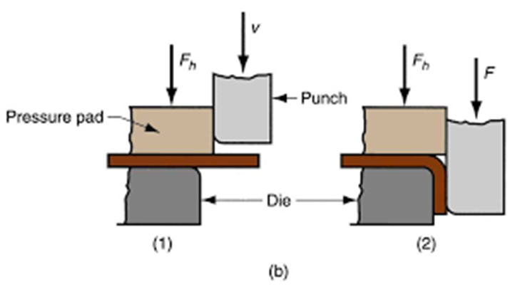
Edge bending involves cantilever loading of the sheet metal. A pressure pad is used to apply a force Fh to hold the base of the part against the die, while the punch forces the part to yield and bend over the edge of the die. In the setup shown in edge bending is limited to bends of 90° or less. More complicated wiping dies can be designed for bend angles greater than 90°. Because of the pressure pad, wiping dies are more complicated and costly than V-dies and are generally used for high-production work.
Q15) What is Bending dies? Explain V bending Die.
A16) Bending dies
Bending dies are used to deform sheet metal along a straight axis; the various methods of bending include wipe bending, V bending, rotary bending, edge bending
V bending die
In V-bending, the sheet metal is bent between a V-shaped punch and die. Included angles ranging from very obtuse to very acute can be made with V-dies. V-bending is generally used for low-production operations. It is often performed on a press brake, and the associated V-dies are relatively simple and inexpensive.

Q16) Explain the method of reducing forces.
A16) Methods of reducing forces
In the process of cutting, very high forces are applied for a short interval of time which gives shock or impulse. The reduction in cutting forces is achieved by arranging for a gradual cut instead of sudden cut of the stock for these following methods are applied: - Flat punched and dies require a maximum of power. To reduce the shear force, the punch or die face should be ground at an angle so that the cutting action is progressive. Think of using scissors that cut the stock, such as paper. Punches and dies that have a die face that angle slightly behave in the same way. This distributes the greater shearing action over a greater length of the stroke and can reduce the power required up to 50%.
Q17) Explain Formability.
A17) Formability
Formability is the ability of a given metal workpiece to undergo plastic deformation without being damaged. The plastic deformation capacity of metallic materials, however, is limited to a certain extent, at which point, the material could experience tearing or fracture (breakage).
Processes affected by the formability of a material include: rolling, extrusion, forging, roll forming, stamping, and hydroforming.
After a blank is cut from a larger sheet or coil, it is formed into various shapes by several processes described in the rest of this chapter. We will now briefly review those characteristics of sheet metals that have important effects on these forming operations
Q18) Explain Forming limit diagram.
A18) A forming limit diagram
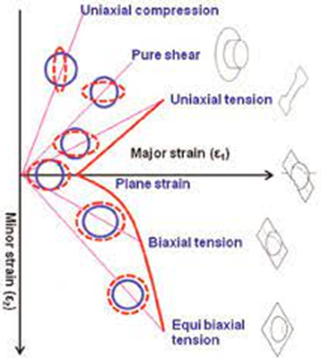
It is also known as a forming limit curve, is used in sheet metal forming for predicting forming behavior of sheet metal. The diagram attempts to provide a graphical description of material failure tests, such as a punched dome test.
Forming limit for sheet forming
One main failure mode is caused by tearing of the material. This is typical for sheet-forming applications. A neck may appear at a certain forming stage. This is an indication of localized plastic deformation. Whereas more or less homogeneous deformation takes place in and around the subsequent neck location in the early stable deformation stage, almost all deformation is concentrated in the neck zone during the quasi-stable and unstable deformation phase. This leads to material failure manifested by tearing. Forming-limit curves depict the extreme, but still possible, deformation which a sheet material may undergo during any stage of the stamping process. These limits depend on the deformation mode and the ratio of the surface strains. The major surface strain has a minimum value when plane strain deformation occurs, which means that the corresponding minor surface strain is zero. Forming limits are a specific material property. Typical plane strain values range from 10% for high-strength grades and 50% or above for mild-strength materials and those with very good formability. Forming limit diagrams are often used to graphically or mathematically represent formability. It is recognized by many authors that the nature of fracture and therefore the Forming limit diagrams are intrinsically non-deterministic since large variations might be observed even within a single experimental campaign.
Q19) Explain Forming limit criteria.
A19) A forming limit diagram
It is also known as a forming limit curve, is used in sheet metal forming for predicting forming behavior of sheet metal. The diagram attempts to provide a graphical description of material failure tests, such as a punched dome test.
Forming limit for sheet forming
One main failure mode is caused by tearing of the material. This is typical for sheet-forming applications. A neck may appear at a certain forming stage. This is an indication of localized plastic deformation. Whereas more or less homogeneous deformation takes place in and around the subsequent neck location in the early stable deformation stage, almost all deformation is concentrated in the neck zone during the quasi-stable and unstable deformation phase. This leads to material failure manifested by tearing. Forming-limit curves depict the extreme, but still possible, deformation which a sheet material may undergo during any stage of the stamping process. These limits depend on the deformation mode and the ratio of the surface strains. The major surface strain has a minimum value when plane strain deformation occurs, which means that the corresponding minor surface strain is zero. Forming limits are a specific material property. Typical plane strain values range from 10% for high-strength grades and 50% or above for mild-strength materials and those with very good formability. Forming limit diagrams are often used to graphically or mathematically represent formability. It is recognized by many authors that the nature of fracture and therefore the Forming limit diagrams are intrinsically non-deterministic since large variations might be observed even within a single experimental campaign.
Forming limit criteria
Tensile test only provides ductility, work hardening, but it is in a uniaxial tension with frictionless, which cannot truly represent material behaviours obtained from unequal biaxial stretching occurring in sheet metal forming. Sheet metal formability tests are designed to measure the ductility of a material under condition similar to those found in sheet metal forming.
Q20) Define Dies and its types.
A20) Die:
The die may be defined as the female part of a complete tool for producing work in a press. It is also referred to a complete tool consists of a pair of mating members for producing work in a press.
Types of dies:
The dies may be classified according to the type of press operation and according to the method of operation.
(A): According to type of press operation:
According to this criterion, the dies may be classified as cutting dies and forming dies.
1: Cutting Dies:
These dies are used to cut the metal. They utilize the cutting or shearing action. The common cutting dies are: blanking dies, perforating dies, notching dies, trimming, shaving and nibbling dies.
2: Forming Dies:
These dies change the appearance of the blank without removing any stock. Theses dies include bending, drawing and squeezing dies etc.
(B) According to the method of operation:
According to this criterion, the dies may be classified as: single operation or simple dies, compound dies, combination dies, progressive dies, transfer dies and multiple dies.
1: Simple Dies:
Simple dies or single action dies perform single operation for each stroke of the press slide. The operation may be one of the operations listed under cutting or forming dies.
2: Compound Dies:
In these dies, two or more operations may be performed at one station. Such dies are considered as cutting tools since, only cutting operations are carried out. Figure shows a simple compound die in which a washer is made by one stroke of the press. The washer is produced by simulation blanking and piercing operations. Compound dies are more accurate and economical in production as compared to single operation dies.
3: Combination Dies:
In this die also, more than one operation may be performed at one station. It is difficult from compound die in that in this die, a cutting operation is combined with a bending or drawing operation, due to that it is called combination die.
4: Progressive Dies:
A progressive or follow-on die has a series of operations. At each station, an operation is performed on a work piece during a stroke of the press. Between stroke the piece in the metal strip is transferred to the next station. A finished work piece is made at each stroke of the press. While the piercing punch cuts a hole in the stroke, the blanking punch blanks out a portion of the metal in which a hole had been pierced at a previous station. Thus, after the first stroke, when only a hole will be punched, each stroke of the press produces a finished washer.

6: Transfer Dies:
Unlike the progressive dies where the stroke is fed progressively from one station to another. In transfer dies the already cut blanks are fed mechanically from one station to other station.
7: Multiple Dies:
Multiple or gang dies produce two or more work piece at each stroke of the press. A gang or number of simple dies and punches are ganged together to produced two or more parts at each stoke of the press.