Unit - 4
Welding Processes
Q1) Explain the classification of joining process.
A1) Classification of joining processes
The process of joining two similar or dissimilar materials is referred as joining process. The joining process is referred as joining process, when there is the use of fasteners to joint them.
The term ‘joining’ is mainly used for welding, brazing, soldering, and adhesive bonding that form a permanent or a temporary joint between the parts. Permanent joint is referred to a joint that cannot easily be separated while temporary joint is the joint that can be easily separated when required.
The joining process can be divided into a liquid state joining or a solid-state joining process.
These processes are primarily used for the assembly of the machine to join various parts either permanently or temporarily.
Joining process generally contains the processes like welding, brazing, soldering, joining, adhesive bonding, etc.
Welding process is the most widely used process for a permanent joint. While joining process is most widely used process for temporary joint.
Joining process can be divided into three types:

b. Semi-permanent fastening process: It includes snap fit, Blind rivet, press fit, etc.
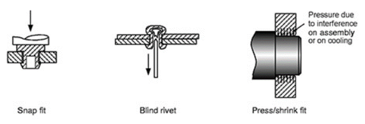
c. Non-permanent fastening process: When the joint required is temporary, then non-permanent fastening process is used. It includes Retaining, self-tapping, nut-bolt assembly, etc.

Q2) Explain Welding terminology.
A2) Welding is referred a material joining process where two or more parts are joined at their contacting surfaces through appropriate application of heat and pressure. Most of the welding processes are achieved via means of heat alone or with pressure alone. In few welding processes, filler material is introduced to facilitate bonding. The assemblage of elements which are joined by welding is known as weldment. Welding is most commonly related to metal parts, whereas the process is additionally used for joining plastics.
WELDING TERMINOLOGY
Actual Throat: The shortest distance between the weld root and the face of a fillet weld.
Air Carbon Arc Cutting (CAC-A): A cutting process by which metals are melted by the heat of an arc using a carbon electrode. Molten metal is forced away from the cut by a blast of forced air.
Alternating Current (AC): An electrical current that reverses its direction at regular intervals, such as 60 cycles alternating current (AC), or 60 hertz.
Arc: The physical gap between the end of the electrode and the base metal. The physical gap causes heat due to resistance of current flow and arc rays.
AWS: American Welding Society.
Constant Current (CC) Welding Machine: These welding machines have limited maximum short circuit current. They have a negative volt-amp curve and are often referred to as “droopers”.
a relatively flat volt-amp curve.
Flux Cored Arc Welding (FCAW): An arc welding process which melts and joins metals by heating them with an arc between a continuous, consumable electrode wire and the work. Shielding is obtained from a flux contained within the electrode core. Added shielding may or may not be provided from externally supplied gas or gas mixture.
Gas Metal Arc Welding (GMAW): See MIG Welding.
Gas Tungsten Arc Welding (GTAW): See TIG Welding.
Carbon Steel, Bronze, Aluminum and Monel are just some of the materials we are certified and experienced in working with.
MIG Welding (GMAW or Gas Metal Arc Welding): Also referred to as solid wire welding. An arc welding process which joins metals by heating them with an arc. The arc is between a continuously fed filler metal (consumable) electrode and the work piece. Externally supplied gas or gas mixtures provide shielding.
Pulsed MIG (MIG-P): A modified spray transfer process that produces no spatter because the wire does not touch the weld puddle. Applications best suited for pulsed MIG are those currently using the short circuit transfer method for welding steel, 14 gauge (1.8 mm) and up.
Pulsed TIG (TIG-P): A modified TIG process appropriate for welding thinner materials.
Shielded Metal Arc Welding: See Stick Welding.
Shielding Gas: Protective gas used to prevent atmospheric contamination of the weld pool.
Spatter: The metal particles blown away from the welding arc. These particles do not become part of the completed weld.
Spot Welding: Usually made on materials having some type of overlapping joint design. Can refer to resistance, MIG or TIG spot welding. Resistance spot welds are made from electrodes on both sides of the joint, while TIG and MIG spots are made from one side only.
Stick Welding (SMAW or Shielded Metal Arc): An arc welding process which melts and joins metals by heating them with an arc, between a covered metal electrode and the work. Shielding gas is obtained from the electrode outer coating, often called flux. Filler metal is primarily obtained from the electrode core.
Stud Welding: A technique similar to flash welding where a fastener or specially formed nut is welded onto another metal part, typically a base metal or substrate.
Submerged Arc Welding (SAW): A process by which metals are joined by an arc or arcs between a bare metal electrode or electrodes and the work. Shielding is supplied by a granular, fusible material usually brought to the work from a flux hopper. Typically provides deeper base metal penetration and fusion.
Tungsten Inert Gas (TIG) Welding: A welding method where an electric arc is maintained between a non-consumable tungsten electrode and the part to be welded. The TIG or GTAW torch feeds inert gas, such as Argon or Helium, to serve as a barrier between the weld and contaminants that may be present in the surrounding air.
Weld Metal: The electrode and base metal that was melted while welding was taking place. This forms the welding bead.
Q3) Define different types of Joint.
A3) Types of joints
The term ‘weld joint design’ refers to the way pieces of metal are put together or aligned with each other. Each joint’s design affects the quality and cost of the completed weld. Selecting the most appropriate joint design for a welding job requires special attention and skill
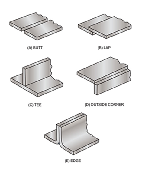
There are five basic welding joint types commonly used in the industry, according to the AWS:
• Butt joint
• Tee joint
• Corner joint
• Lap joint
• Edge joint
Butt Joint Welding
A butt joint is a joint where two pieces of metal are placed together in the same plane, and the side of each metal is joined by welding. A butt weld is the most common type of joint that is used in the fabrication of structures and piping systems. It’s fairly simple to prepare, and there are many different variations that can be applied to achieve the desired result.
Butt welds are made in a variety of ways, and each one serves a different purpose. Varying factors include the shape of the groove, layering and width of the gap. Listed below are some typical examples of butt weld joints.
• Square
• Single bevel
• Double bevel
• Single J
• Double J
• Single V
• Double V
• Single U
• Double U grooves
The area of the metal’s surface that is melted during the welding process is called the faying surface. The faying surface can be shaped before welding to increase the weld’s strength, which is called edge preparation. The edge preparation may be the same on both members of the butt joint, or each side can be shaped differently.
Reasons for preparing the faying surfaces for welding include the following:
• Codes and standards
• Metals
• Deeper weld penetration
• Smooth appearance
• Increased strength
In some cases, the exact size, shape and angle can be specified for a groove. If exact dimensions are not given, the groove can be made to the necessary size. However, it’s important to remember that the wider the groove, the more welding it will require to complete.
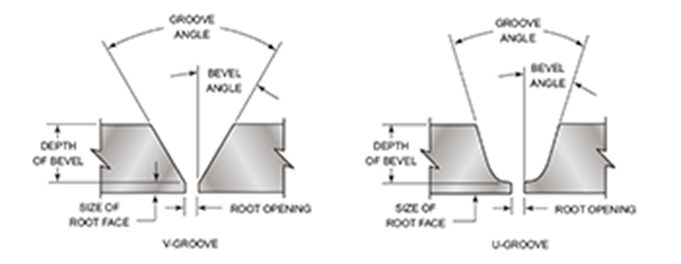
As the metal becomes thicker, you must change the joint design to ensure a sound weld. On thin sections, it is often possible to make full penetration welds using a square butt joint. When welding on a thick plate or pipe, it is often impossible for the welder to get 100% penetration without some type of groove being used.
When it comes to butt joints, commonly occurring defects may include burn through, porosity, cracking or incomplete penetration. However, these can be avoided by modifying the welding variables.
Tee Joint Welding
Tee welding joints are formed when two pieces intersect at a 90° angle. This results in the edges coming together in the center of a plate or component in a ‘T’ shape. Tee joints are considered to be a type of fillet weld, and they can also be formed when a tube or pipe is welded onto a base plate.

With this type of weld, it’s important to always ensure there is effective penetration into the roof of the weld. There are a handful of welding styles that can be used to create a tee joint:
• Plug weld
• Slot weld
• Bevel-groove weld
• Fillet weld
• J-groove weld
• Melt-through weld
• Flare-bevel-groove weld
Tee joints are not usually prepared with groove, unless the base metal is thick and welding on both sides cannot withstand the load the joint must support. A common defect that occurs with tee joints is lamellar tearing—which happens due to restriction experienced by the joint. To prevent this, welders will often place a stopper to prevent joint deformities.
Corner Joint Welding
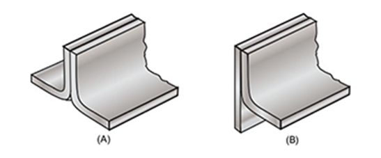
Corner joints have similarities to tee welding joints. However, the difference is the location of where the metal is positioned. In the tee joint, it’s placed in the middle, whereas corner joints meet in the ‘corner’ in either an open or closed manner—forming an ‘L’ shape.
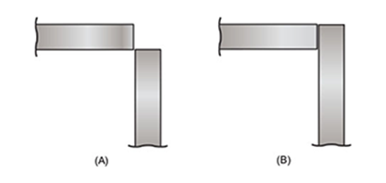
These types of joints are among some of the most common in the sheet metal industry, such as in the construction of frames, boxes and other applications. There are two ways of fitting up an outside corner joint—either it forms a V-groove (A) or forms a square butt joint (B), as seen in the diagram below.
The styles used for creating corner joints include V-groove, J-groove, U-groove, spot, edge, fillet, corner-flange, bevel-groove, flare-V-groove and square-groove or butt.
Lap Joint Welding
Lap welding joints are essentially a modified version of the butt joint. They are formed when two pieces of metal are placed in an overlapping pattern on top of each other. They are most commonly used to joint two pieces with differing thicknesses together. Welds can be made on one or both sides.

Lap joints are rarely used on thicker materials, and are commonly used for sheet metal. Potential drawbacks to this type of welding joint include lamellar tearing or corrosion due to overlapping materials. However, as with anything, this can be prevented by using correct technique and modifying variables as necessary.
Edge Joint Welding
In an edge joint, the metal surfaces are placed together so that the edges are even. One or both plates may be formed by bending them at an angle.
The purpose of a weld joint is to join parts together so that the stresses are distributed. The forces causing stresses in welded joints are tensile, compression, bending, torsion and shear, as seen in the image below.
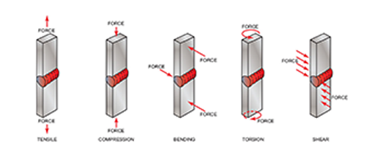
The ability of a welded joint to withstand these forces depends upon both the joint design and the weld integrity. Some joints can withstand certain types of forces better than others.
The welding process to be used has a major effect on the selection of the joint design. Each welding process has characteristics that affect its performance. The rate of travel, penetration, deposition rate and heat input also affect the welds used on some joint designs. The following styles are applicable for edge joints:
• U-groove
• V-groove
• J-groove
• Corner-flange
• Bevel-groove
• Square-groove
• Edge-flange
Due to overlapping parts, this type of joint is more prone to corrosion. Welders must keep in mind other defects like slag inclusion, lack of fusion and porosity, which can also occur.
Q4) Explain Principle and equipments of single carbon arc welding.
A4) Carbon arc welding (CAW) is a process which produces coalescence of metals by heating them with an arc between a non-consumable carbon (graphite) electrode and the work-piece. It was the first arc-welding process developed but is not used for many applications today, having been replaced by twin-carbon-arc welding and other variations. The purpose of arc welding is to form a bond between separate metals. In carbon-arc welding a carbon electrode is used to produce an electric arc between the electrode and the materials being bonded. This arc produces temperatures in excess of 3,000 °C. At this temperature the separate metals form a bond and become welded together.
Q5) Explain FCAW
A5) FCAW
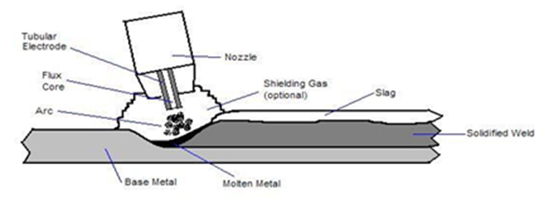
Flux-cored arc welding (FCAW or FCA) is a semi-automatic or automatic arc welding process. FCAW requires a continuously-fed consumable tubular electrode containing a flux and a constant-voltage or, less commonly, a constant-current welding power supply. An externally supplied shielding gas is sometimes used, but often the flux itself is relied upon to generate the necessary protection from the atmosphere, producing both gaseous protection and liquid slag protecting the weld. The process is widely used in construction because of its high welding speed and portability.
FCAW was first developed in the early 1950s as an alternative to shielded metal arc welding (SMAW). The advantage of FCAW over SMAW is that the use of the stick electrodes used in SMAW is unnecessary. This helped FCAW to overcome many of the restrictions associated with SMAW.
Q6) Explain TIG.
A6) TIG
Tungsten inert gas (TIG) welding or gas tungsten arc is an inert gas shielded arc welding using a non-consumable electrode. This electric arc is produced by the passage of current through a conductive ionized inert gas that provides shielding of the electrode, molten weld pool, and solidifying weld metal from contamination by the atmosphere. The process may be used with or without the addition of filler metal using metal rods. (a) The gas tungsten arc welding process, formerly known as TIG (for tungsten g inert-gas) welding. (b) Equipment for gas tungsten-arc welding operations.
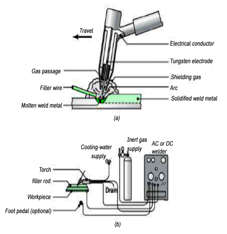
Electrode: In TIG welding, tungsten refers to the element used on the electrode. The function of the electrode is to serve as one of the electric terminals which supply the heat required to the weld. Care must be taken so that the tungsten electrode does not come in contact with the weld pool in any way to avoid its contamination resulting in the faulty weld. Pure tungsten is less expensive and will carry less current. Some other elements may be added to the tungsten, like cerium, lanthanum, thorium, and zirconium creating electrode alloys to improve arc stability, emissivity, and bring higher melting points. The electrode may contain 1 to 2% thoria (thorium oxide) mixed along with the core tungsten or tungsten with 0. 15 to 0. 40% zirconia (zirconium oxide). The thoriated tungsten electrodes carry a high current, and more desirable as they can strike, and maintain a stable arc. The zirconia added with tungsten is better than pure tungsten but inferior to the thoriated tungsten electrode.
Tungsten inert gas welding set up: It consists of a welding torch at the center of which is the tungsten electrode. The inert gas supplied to the welding zone through the annular path surrounding the tungsten electrode to effectively displace the atmosphere around the weld puddle.
Q7) Explain MIG.
A7) MIG
This is also known as Metal inert-gas arc welding (MIG) because it utilizes a consumable electrode. Other gas-shielded arc-welding processes are utilizing consumable electrodes such as flux-cored arc welding, all of which coming under MIG. It’s quite stable for thicker sheets because filler metal requirement in the welding process makes gas-tungsten arc welding (GTAW or TIG) difficult to use, which is more suitable for thin sheets. (a) Schematic illustration of the gas metal-arc welding process, formerly known as MIG (for metal inert-gas) welding. (b) Basic equipment used in gas metal-arc welding operations.
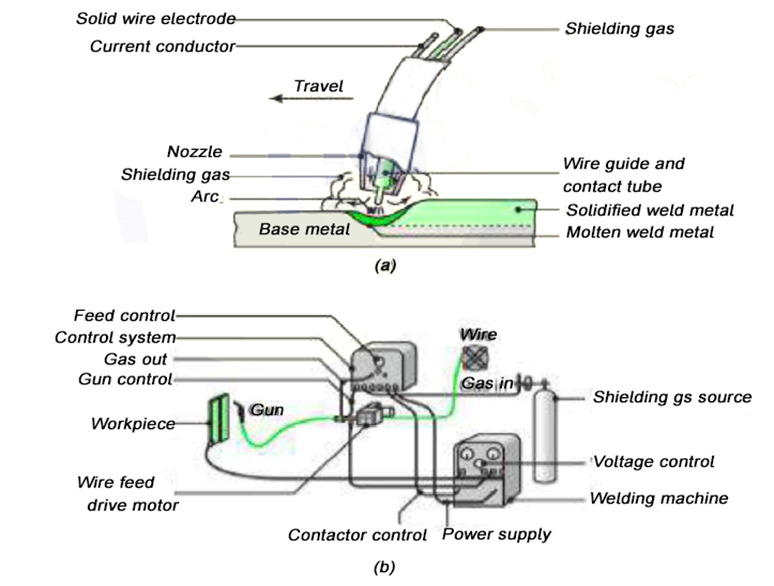
The consumable electrode is in the form of a wire reel fed at a constant rate through the feed rollers. The welding torch is connected to the gas supply cylinder, which provides the necessary inert gas. The electrode and the work piece are connected to the welding power supply. The power supply is always of the constant voltage type. The current from the welding machine is changed by the rate of feeding of the electrode wire. Normally, DC arc-welding machines are used for GMAW with electrode positive (DCEP). The DCEP increases the metal- deposition rate, and also provides a stable arc and smooth electrode metal transfer. With DCEN the arc becomes highly unstable, and also results in spatter. But special electrodes having calcium, and titanium oxide mixtures as coatings are found to be good for steel with DCEN.
Metal Transfer
The short-circuiting metal transfer occurs with relatively low current settings of the order of 75 to 175 A for an electrode diameter of 0. 9 mm. The number of times that the pinching takes place depends on the inductance of the welding machine used, and the parameters set. The rate at which the short-circuiting current increases is controlled by the inductance of the welding machines. Too low an inductance gives rise to a very high short-circuiting current, and consequently a high pinching rate. With high inductance, the short-circuiting becomes low and results in a somewhat lower pinching force. The effect of inductance is measured in terms of response rate (raising rate of current due to short-circuiting, kA/s). It can be observed that the optimum response rate depends on the electrode wire size. Hence, he is welding machines to be used for short-circuiting transfer make use of a variable choke system which can be tuned for different wire sizes. The frequency of metal transfer may be of the order of 50 to 200per second. This rate also depends on the open-circuit voltage, and wire-feed rate employed.
Shielding gases
Argon, helium, nitrogen, oxygen, carbon dioxide, and a mixture of the above gases in various proportions are used in GMAW as shielding gases. Argon is the most widely used of all the shielding gases, because it reduces the spatter, and concentrates the arc, which in turn gives deep penetration welds. Besides, argon ionizes easily requiring smaller arc voltages, and also has lower thermal conductivity, and hence conducts heat very slowly from the arc to the weld zone. Thus, it is good for welding thin sheets. Because of the lower voltages employed, it is suitable for out-of-position welding. For spray transfer of metal, a large percentage of argon is required. Helium is the most expensive of all the shielding gases. Due to its better thermal conductivity, it is suitable for thicker sheets as well as for metals having higher thermal conductivity such as copper, and aluminum. The filler metal-deposition rate by helium is much higher compared to argon because of the higher current-carrying capacity. The arc in carbon dioxide shielding gas is unstable, and therefore a short arc is to be used to reduce the metal spatter. It is the least expensive of all the shielding gases. Since about 7. 5% of the carbon dioxide decomposes into carbon monoxide, and oxygen in the arc, deoxidizers such as aluminum, and silicon are to be used while using carbon dioxide. It is a heavy gas, and therefore it covers the weld zone very well. The metal transfer is globular only with the carbon dioxide shielding gas. Sometimes the mixtures of gases such as argon-helium, argon-carbon dioxide, argon-oxygen are used for special applications. Shielding gases should always flow in a laminar manner without causing any turbulence because turbulence causes weld contamination. The gas flow rates to be used depend upon the thickness of the sheet being welded, the position of the weld as well as the base material.
Electrodes
The electrode wire comes generally in the form of coils, and normal sizes may be of the order of 0. 5 to 3. 2 mm. Depending upon the base material, various wire compositions are available. For steels, electrodes wire having deoxidizers are used because the deoxidizers help in the reduction of oxidation of the weld metal as well as the porosity. The electrode wire is produced by wire drawing, and uniform diameter throughout otherwise the arc may saunter.
Q8) Explain SAW.
A8) SAW
Submerged arc welding is used for faster welding jobs. It is possible to use larger welding electrodes (12 mm) as well as very high currents (4000 A) so that very high metal deposition rates of the order of 20 kg/h or more can be achieved with this process. Also, very high welding speeds (5 m/min) are possible in a saw. Some submerged arc welding machines can weld plates of thicknesses as high as 75 mm in butt joint in a single pass. Though it can weld very small thickness, of the order of 1 mm, it is very economical for larger welds only. Schematic illustration of the submerged-arc welding process, and equipment. The un-fused flux is recovered and reused.
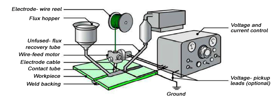
The arc is produced in the same manner as in GMAW. The welding zone is completely covered by means of a large amount of granulated flux, which is delivered ahead of the welding electrode by means of a flux-feed tube. The arc between the electrode and the workpiece is completely submerged under the flux and is not visible from the outside. A part of the flux melts and forms the slag, which covers the weld metal. The unused flux can be recycled. The power source used with submerged arc welding can either be AC or DC. Both constant voltage and constant current type machines can effectively use though, for larger electrodes a constant-current type of power supply is used. The current ratings of the SAW machines are, in general, two to three times higher than those of the GMAW machines. Arc blow is not encountered with AC supply with a single wire SAW. But sometimes two wires may be used to deposit larger amounts of metal. These two electrodes being connected to two separate power sources, the arc blow is likely to occur because of the interference of the two magnetic fields surrounding the two electrodes, if the two currents are in phase. To avoid the setting of opposite magnetic fields, the two power supplies are adjusted in such a way that, one of the supplies is in a peak, and the other is set to zero current. One of the electrodes is called leading, and the other is called trailing. In this way, the aforementioned problem is reduced. There is no spatter of the molten metal since the arc is completely submerged in the flux. Because of the usage of loose granulated flux to cover the joint, it is difficult to carry out in any position other than the flat or down-hand position. Also, because of the large metal pool generation in the SAW process, the out-of-position welds are difficult to carry out. The electrode wires normally used are of sizes 1. 6, 2, 2. 5, 3. 15, 4, 5, 6. 3, and 8mm. The wires should be smooth with no surface imperfections or contaminants. It is difficult to manually feed the wire into the joint because of the very high wire-feed rate. As the SAW process produces a large amount of molten weld metal, it takes sometimes for solidification. Hence, it is imperative in SAW to provide some way of containing this molten metal. Weld metal backing is normally used. The backing slaves can be with or without grooves, but in general, copper plates are used, which can easily be cooked with internal running water, when necessary. For thin plates, plain copper backing plates without any cooling water would be enough. Pure copper removes heat quickly from the molten weld pool because of its high thermal conductivity.
Q9) Define Spot, seam projection weld process
A9) Spot, seam projection weld process
Resistance welding processes differ from other welding processes in that no fluxes are employed, the filler metal is rarely used, and the joints are often of the lap type. The amount of heat generated in the workpiece depends on the magnitude of the current, the resistance of the current-conducting path, and the time for which the current is made to flow.
This is expressed in terms of joule heating. By the simple application of Ohm’s law, the voltage (V) required for a current flow (I) is given by the relationship
V = IR,
where R is the resistance offered by the workpiece to the flow of current.
The heat generated is, thus, expressed by the formula:
H = IVt
= I (IR) t
= I2 Rt
where, H = heat generated, joules
I = current, rms amperes
R = resistance, ohms
t = time of current flow, seconds.
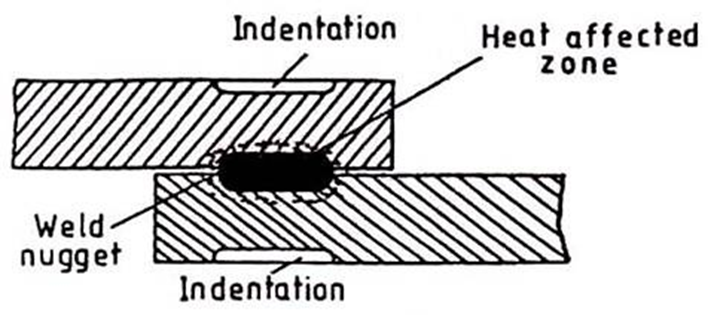
The heat generated is, thus, directly proportional to the resistance offered by any point in the circuit. As the interface of the two surfaces forming the lap joint is the point of greatest resistance, it is also the point of greatest heat. In simple resistance welding processes, a low voltage high amperage current flows from one adjoining plate to the other until the metal at the interface is heated to a high enough temperature to cause localized fusion which under the applied pressure squeezes the molten metal from the two parts to a homogenous mass called the weld nugget, as shown in Fig.
Resistance Spot Welding:
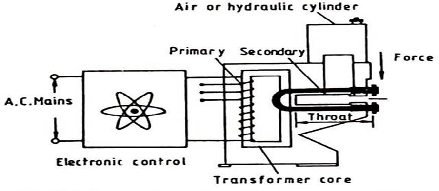
In this process, overlapping sheets are joined by local fusion, at the interface, by the concentration of current flowing between two electrodes. It is characterized by low cost, high speed, and dependability making it, at present the most widely used resistance welding process. Fig. shows the essential features of the process, and the basic circuit components are shown in Fig.
Spot Welding Sequence
All resistance welding operations are automatic, and therefore all process variables are pre-set, and maintained constant. Once a welding operation has been initiated there is no way in which its progress can be controlled, and, thus, the weld cycle is completed as per the pre-set times.
Welding Cycle:
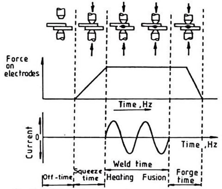
The welding cycle for spot, seam, and projection welding consists basically of four elements viz., squeeze time, weld time, hold time, and off time. These timings are pre-set for a particular metal, and a thickness range and the shop operator normally cannot change them on his own. Each one of these four-time phases has its role to play in achieving a sound weld of the required size.
Squeeze Time:
The time interval between the application of electrode pressure to the work, and switching on the welding current is called the squeeze time. This time interval is provided to assure the contact between the electrode, and the work, and to initiate the application of force on it.
Weld Time:
It is the time for which the welding current flows to melt the metal at the interface.
Hold Time:
It is the time for which the electrodes are kept in position, after the welding current is switched off, to assure the application of pressure to consolidate the molten metal into a nugget which is then cooled by the dissipation of heat to the surrounding work material. If the applied force is excessive it may result in the expulsion of molten metal from in-between the sheets.
Off Time:
The time allowed to shift the work to the next location before the cycle is repeated is referred to as the off-time. The electrodes are kept off the work during this time interval.
All these phases of a weld cycle are shown in fig. 12. 4:
Machine Rating:
The actual welding is done in the secondary circuit of the resistance welding machine but the voltage is not known, and the current flowing, for a fraction of a second for each weld cycle, is very heavy. It is, therefore, not easy or economical to measure these electrical parameters in the secondary circuit. The machine rating is, thus, based upon the current drawn by the system at the mains supply, and is given in the KVA unit. Some part of this power is lost in the system which goes to heat up the windings, and stampings.
This leads to a rise in temperature of the transformer which necessitates water cooling of the system otherwise the insulation may get damaged. To give a higher margin of safety the KVA ratings of these machines are quoted based upon the power that can be drawn for thirty seconds in each minute, this accounts for the cooling requirements of the system. The KVA rating of the resistance welding machines for spot, seam, and projection welding, normally varies between 5 to 500 KVA.
Spot Welding Electrodes:Electrodes are an important part of a resistance spot welding unit. They serve four important functions viz., conduct the welding current to the work, transmit the desired force to the workpieces, dissipate a part of the heat from the work, and provide jigging action to it.
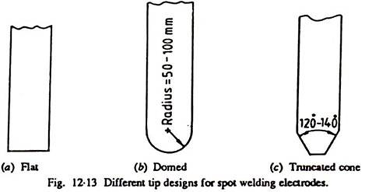
To achieve the desired current density, it is important to have a proper electrode shape for which three main types of electrodes are used; these are pointed, domed, and flat electrodes.
Pointed tips are most widely used particularly for ferrous materials; with continued wear, they mushroom uniformly. The pointed electrodes are basically truncated cone electrodes with an angle of 120° – 140°. Compared with other types, the contact area can be controlled more accurately with a truncated cone or pointed electrodes, and any wear in service can be easily seen. However, the pointed tip electrodes make more obvious surface marking on the workpiece, and require more accurate alignment.
Domed electrodes are characterized by their ability to withstand heavier pressure and severe heating without mushrooming which makes them particularly useful for welding non-ferrous metals. The radius of the dome varies but a 50 to 100 mm radius is most commonly used. Filing of electrodes while on the machine should not be permitted as it is not possible to reproduce their original shape by that method.
When inconspicuous or invisible welds are desired or where the weld indentation is to be minimum, a flat lip electrode is used. A combination of one flat and one domed electrode is usually used in such cases. All three types of electrodes are shown in Fig.10
Offset electrodes can be used to make spot welds in places that are inaccessible to weld by conventional type electrodes e. g., for making comer welds, and for welding parts with overhanging flanges as shown in Fig. 11. If there is excessive off-set undue tip deflection, skidding, and surface deformation may result. If the size of the electrode is restricted to accommodate the joint, overheating may result.

Spot welding electrodes are made of materials with higher electrical, and thermal resistivities, and with sufficient strength to withstand high pressure at elevated temperatures, for example, copper-base alloys such as copper beryllium, and copper tungsten are often chosen for the purpose.
Q10) Define Heat Balance in resistance welding.
A10) Quite often sheets of different thicknesses or dissimilar materials are required to be spot welded. Such situations result in heat dissipation or generation of different amounts from the two sheets (or workpieces) which may cause the nugget to develop with its centerline away from the interface resulting in a weak weld. To achieve symmetrical growth of nugget on both sides of the interface it is essential to control the pattern of heat generation (or dissipation).
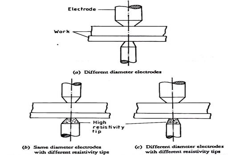
This is done by using electrodes of different diameters or by using high resistivity inserts, such as that of tungsten, in one of the electrodes. The weld nugget will then develop closer to the electrode with a smaller diameter due to the higher current density or electrode with high resistivity tip due to reduced thermal conductivity hence lower heat dissipation.
Four cases may arise for spot welding two sheets:
(i) Sheets of the same material but different thicknesses,
(ii) Sheets of different materials but the same thickness,
(iii) Thinner sheet of higher electrical resistivity (or lower electrical conductivity),
(iv) Thinner sheet of lower electrical resistivity (or higher electrical conductivity).
In the light of the above discussion the solution for these cases will be as follows:
(i) Thicker sheet has higher resistance (R = ρ 1/a, more thickness means longer 1, therefore higher R, as resistivity (ρ) of the material is constant at a given temperature) or lower conductivity (α), (α =√ρ)/and the nugget tends to penetrate deeper into it.
Therefore, use a bigger diameter electrode on the side of the thicker sheet. Heat balance can thus be achieved by decreasing the current density in the thicker sheet or by decreasing the heat loss for the thinner sheet by using high resistivity (or low conductivity) tip or maybe by a combination of both the methods as shown in Fig. 13.
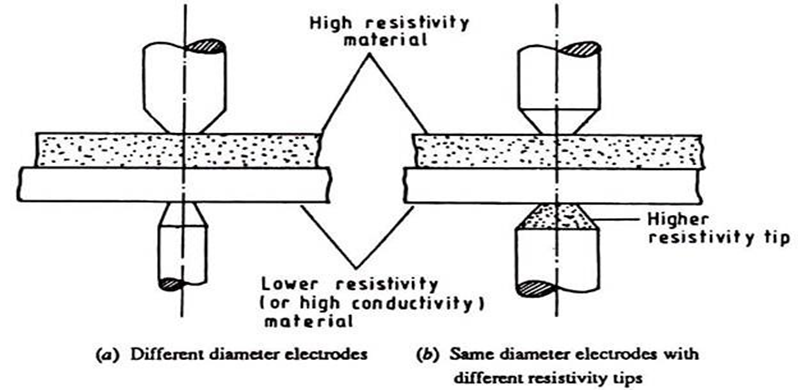
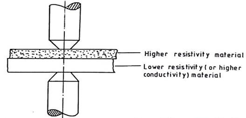
(ii) For sheets of different materials but the same thickness, resistance will depend directly on resistivity. Thus, more heat will be generated in a material with higher resistivity (or lower conductivity).
Therefore, use an electrode with a larger diameter on high resistivity (or lower conductivity) material. Alternatively, use an electrode with a high resistivity tip on the lower resistivity material as shown in Fig.
(iii) With a thinner sheet of higher electrical resistivity, the case may be self-compensating. Therefore, depending upon the cumulative effects of resistivity, and thickness the electrodes can be chosen as per the net effect which if completely compensated for may result in the use of same the diameter electrodes, as shown in Fig.
(iv) With a thicker sheet of higher resistivity, the differential effect of thickness and resistivity will be accentuating hence the use of a large diameter electrode on the side of the thicker sheet, and at the same time use of an electrode with a smaller diameter, and higher resistivity tip on the side of the thinner sheet may be required to get a completely symmetrically placed nugget as shown in Fig.
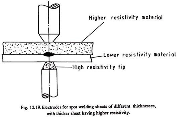
Fig. Electrodes for spot welding sheets of different thicknesses, with a thicker sheet having higher resistivity.
Q11) Explain Heat balance:
A11) Heat Balance:
Due to the collapse of projection during the welding operation, there is a tendency for the part containing projections to get hotter than the other part. That is why in projection welding dissimilar materials projections are made on material with higher thermal conductivity. As in spot welding, the nugget is formed closer to the electrode with low thermal conductivity. Thus, heat balance can be achieved when required by manipulation of these factors.
Applications:
One of the attractive features of projection welding is that it gives longer electrode life, as the electrodes can be made of harder material with less wear, and maintenance. The outer surface of the work can be produced without any electrode marks thus eliminating subsequent processing before painting or polishing.
The process is not used for seams longer than 250 mm. It finds wide use in joining small attachments to sheet structures. It is used in the production of automobile bodies, domestic equipment, office furniture, and machine parts.
The maximum thickness ratio of the workpieces which can be welded by this process is 6 to 1. The process is generally used for section thickness ranging from 0. 5 to 4 mm.

Specific applications include welding of captive nuts to chassis panels of automobiles, as shown in Fig.22. Reinforcing rings are often projection welded around holes in sheet metal tanks. Threaded studs can be welded to the backing bar or plate by this process, as is shown in Fig.

Cross-wire welding is another important application of projection welding. Cross-wire products include such items as refrigerator racks, grills of all kinds, lampshade frames, wire baskets, fencing, grating, and concrete reinforcing mesh.
Projection welding can, however, be used for a small group of metals, and alloys. These include low carbon steels, high carbon, and low alloy steels, stainless, and high alloy steels, zinc die castings and titanium.
Q12) Explain Gas welding, and cutting
A12) Gas welding, and cutting
Gas welding is also named oxy-fuel gas welding (OFW). Gas welding derives heat from the combustion of fuel gas such as acetylene in combination with oxygen. The process is a fusion welding process where the joint is completely melted to obtain the fusion. Necessary considerations for gas welding.
Fuel Gases
Fuel gas for Gas welding used is acetylene due to its high temperature in the flame. Thereby the gas welding may be known as oxy-acetylene welding (OAW).
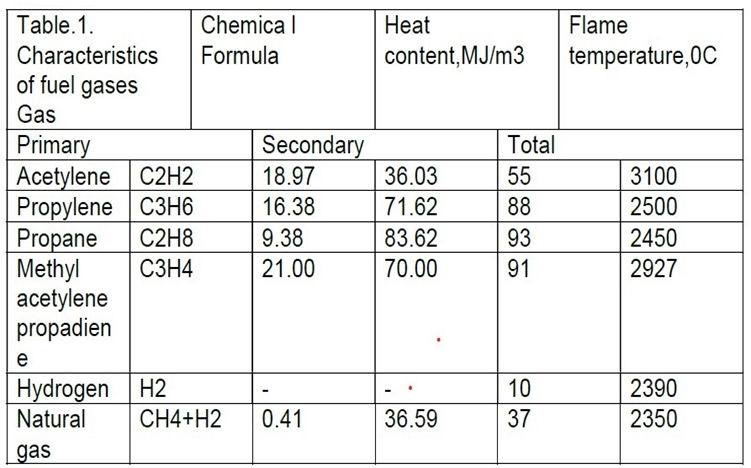
The following table shows the useful fuel gases for gas welding with their calorific values, and temperatures.
Three basic types of oxyacetylene flames are used in oxyfuel gas welding, and cutting operations: (a) neutral flame; (b) oxidizing flame; (c) carburizing, or reducing, flame.
The gas mixture in (a) is equal volumes of oxygen and acetylene.
(d) The principle of the oxyfuel gas welding process.

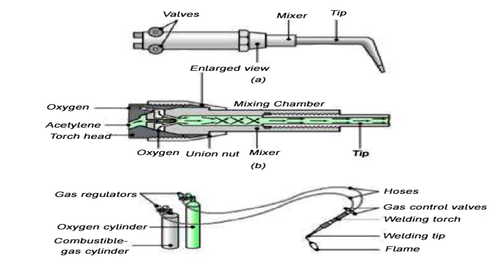
(a) General view of, and (b) cross-section of, a torch used in oxyacetylene welding. The acetylene valve is opened first. The gas is lit with a spark lighter or a pilot light. Then the oxygen valve is opened, and the flame adjusted. (c) Basic equipment used in oxyfuel gas welding. To ensure correct connections, all threads on acetylene fittings are left-handed, whereas those for oxygen are right-handed. Oxygen regulators usually are painted green, and acetylene regulators red.
Schematic illustration of the pressure-gas welding process: (a) before, and
(b) after. Note the formation of a flash at the joint; later the flash can be trimmed off.
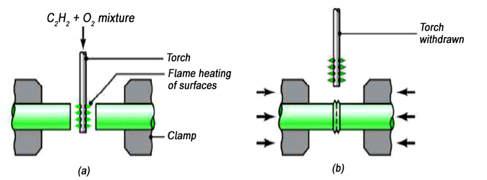
The acetylene valve on the torch is opened slightly with the help of a friction spark lighter. The acetylene valve is opened to get the required flow of acetylene. The oxygen valve is slowly opened till the intermediate flame feather of the reducing flame.
Key points:
1) Gas welding is also named oxy-fuel gas welding (OFW).
2) Gas welding derives heat from the combustion of fuel gas such as acetylene in combination with oxygen
Q13) Explain soldering.
A13) Soldering
Soldering is a process of joining two metals by using another low-temperature metal alloy. The metal used for the joining purpose is called solder. Solders are of two types:
Hard solder is an alloy of copper, and zinc whereas soft solder is an alloy of tin, and lead.
Process
The surfaces to be joined are cleaned, and are placed on each other. A flux is employed to prevent oxidation. Zinc chloride is commonly used for this purpose. The soldering iron is heated either electrically or by some external heat. Then the heart, and is dipped into the flux, and solder is pressed against the surfaces to be joined. A joint is formed by melting the solder.
Applications
Soldering is widely used for sheet metal work, and in radio, and television work for joining wires.
Advantages
Disadvantages
Q14) Difference between soldering, and brazing
A14)
SR. No. | Brazing | Soldering |
1 | Filler metal has the melting point above 400°c | Filler metal has the melting point below 400°c |
2 | More stable joints can be made | Less stable joints can be made |
3 | High pressure, and temperature do not affect the joint | Joints are affected by high temperature, and pressure |
4 | Equipment cost is more | Equipment cost is very low. |
Q15) Explain Brazing.
A15) Brazing
The process of joining two metal surfaces by heating, and adding a non-ferrous alloy with a melting point above 400-degree Celsius is known as brazing.
Process
The surfaces to be joined are cleaned from all oil, dirt oxides. Then both the surfaces are placed in the joining position. Flux is sprinkled or placed on it. The heat is given to the surface and the filler metal. The molten filler metal flows to the surfaces to be joined. On cooling, a brazing joint is formed. The filler metals used are copper, copper alloy, silver alloy, and Aluminium alloys. In brazing, the filler metal melts but the surfaces to be joined remain unmelted. The various methods used to melt the filler metal, and flux are:
Applications
Brazing is used for electrical items, radiators, heat exchangers comma pipes, and pipe fittings, and tooltips.
Advantages
Disadvantages
Key points
1) Soldering is a process of joining two metals by using another low-temperature metal alloy. The metal used for the joining purpose is called solder.
2) The process of joining two metal surfaces by heating, and adding a non-ferrous alloy with a melting point above 400-degree Celsius is known as brazing
Q16) Explain Braze welding.
A16) Braze welding
Braze welding is the use of a bronze or brass filler rod coated with flux to join steel workpieces. The equipment needed for braze welding is basically identical to the equipment used in brazing. Since braze welding usually requires more heat than brazing, acetylene or methylacetylene-propidine (MAP) gas fuel is commonly used. The name comes from the fact that no capillary action is used.
Braze welding has many advantages over fusion welding. It allows the joining of dissimilar metals, minimization of heat distortion, and can reduce the need for extensive pre-heating. Additionally, since the metals joined are not melted in the process, the components retain their original shape; edges and contours are not eroded or changed by the formation of a fillet. Another effect of braze welding is the elimination of stored-up stresses that are often present in fusion welding. This is extremely important in the repair of large castings. The disadvantages are the loss of strength when subjected to high temperatures and the inability to withstand high stresses.
Carbide, cermet and ceramic tips are plated and then joined to steel to make tipped band saws. The plating acts as a braze alloy.
Q17) Explain welding metallurgy and heat affected zone
A17) Welding metallurgy deals with the interaction of different metals and interaction of metals with gases and chemicals of all types. Welding metallurgy describes a microcosm of metallurgical processes occurring in and around a weld that influence the microstructure, properties, and weldability of the material ƒ Due to the rapid heating and cooling rates associated with most welding processes, metallurgical reactions often occur under transient, non-equilibrium conditions
The heat affected zone (HAZ) is a non-melted area of metal that has undergone changes in material properties as a result of being exposed to high temperatures. These changes in material property are usually as a result of welding or high-heat cutting. The HAZ is the area between the weld or cut and the base (unaffected), parent metal.
The HAZ area can vary in severity and size depending on the properties of the materials, the concentration and intensity of the heat, and the welding or cutting process used.
Q18) Define weld inspection
A18) Many characteristics of a weld can be evaluated during welding inspection - some relating to weld size, and others relating to the presence of weld discontinuities. The size of a weld can be extremely important, as it often relates directly to the weld's strength and performance. For instance, undersized welds may not withstand stresses applied during service.
Depending on their size and/or location, weld discontinuities (imperfections within or adjacent to the weld) can prevent the weld from meeting its intended performance. Weld discontinuities are often referred to as welding defects, and they can sometimes cause premature weld failure due to a reduction of strength or added stress concentrations within the welded component.
Weld inspections are conducted for several reasons, the most common of which is to determine whether the weld is of suitable quality for its intended application. To evaluate the quality of a weld, you must first have criteria to which you can compare the weld's characteristics. Codes and standards developed specifically for a variety of welding fabrication applications are used during welding inspections to dictate what levels of weld discontinuities are acceptable. It is important to choose a welding standard that is intended for use within your industry or application.
Quality acceptance criteria can originate from several sources. The welding fabrication drawing or blueprint will typically provide sizes and other dimensional information, such as length and location of welds. These dimensional requirements are typically established through design calculations or are taken from proven designs known to meet the performance requirements of the welded connection.
Q19) Explain External welding defects.
A19) External Welding Defects
External defects are also known as surface of visual defects because they manifest themselves on the surface itself. They include surface cracks, overlaps, undercuts, porosity, and spatter. We will discuss each one of them in the next section.
i. CracksCracks are the most common defects and they can occur anywhere on the surface of the weld material. Some cracks can also be present inside the weld material especially on areas that are affected by direct heat (HAZ). Cracks presents themselves in two major types:
Overlap results when the weld pool overflows on the surface of the weld metal. The molten metal does not fuse with the base metal leading to an overlap which may extend to form an angle not exceeding 90 degrees.
Causes of OverlapsUndercuts presents themselves as narrow gutters on the base metal next to the weld metal near the edge. This occurs when the base metal melts away from the weld area reducing the thickness of the base metal and the result is a weakened workpiece. These undercuts run parallel to the metal weld.
Causes of UndercutsPorosity is a condition that manifests itself inform of gases or air bubbles that are trapped in the weld metal. It is mainly as a result of contamination of the weld metal which is weakened and it can actually collapse with time.
Causes of PorositySpatter occurs when metal particles from the weld is stuck on the area adjacent to the weld area. This defect is common in gas metal arc welding and it is sometimes very hard to remove the particles.
Causes of Spatter
Q20) Define Internal Welding defects.
A20) Internal Welding Defects
These are defects that occur at some depth in the material. They are visually invisible since they are not present on the surface but they carry equal weight as the external ones. These defects include incomplete fusion, slag inclusion, and incomplete penetration.
i. Incomplete FusionLack of fusion or incomplete fusion occurs when the weld metal and the base metal are not accurately welded due to improper melting resulting into unfilled gap. Improper fusion can also occur between layers within the weld itself. Although this is an internal problem, it can be manifested on the outer surface too if the outer sidewall is not properly fused with the parent metal.
Causes of Incomplete fusionIncomplete penetration results when the depth of the weld is not sufficient. As such, the metal grove is not filled fully meaning that the weld does not extend through the entire joint.
Causes of an Incomplete PenetrationSlag inclusions are compounds such as oxides that are mainly trapped in the weld or on the surface of the weld zone. These compounds are byproducts of welding processes such as stick welding and arc welding. In addition, insufficient cleaning can leave some slag behind which reduces the strength of the weld and also it can act as a starting point of serious cracking. Serious slag inclusion may require you to do a re-weld.
Causes of Slag Inclusion