Unit – 6
Manufacturing of Composites
Q1) Define Composites.
A1) Composites exist in nature. A piece of wood is a composite, with long cellulose fibres held together by a substance called lignin. Composite materials are formed by combining two or more materials that have quite different properties, and they do not dissolve or blend into each other. The different materials in the composite work together to give the composite unique properties. Humans have been using composite materials for thousands of years in different areas.
The first uses of composites date back to the 1500 BC, when early Egyptians and Mesopotamian settlers used a mixture of mud and straw to create strong and durable buildings. The combination of mud and straw in a block of brick provides it a strong property against both squeezing and tearing or bending.
The straw continued to provide reinforcement to ancient composite products, including pottery and boats. In 1200 AD, the Mongols invented the first composite bow using a combination of “animal glue”, bone, and wood. The bows were pressed and wrapped with birch bark. These bows were powerful and accurate. Composite Mongolian bows helped to ensure Genghis Khan’s military dominance.
Due to their advantages such as being light weight and strong, many of the greatest advancements in composites were the result of wartime needs. During World War II, many composite materials were developed and moved from the laboratory into actual production.
The development and need for composite materials also result in the fibre-reinforced polymers (FRP) industry. By 1945, more than 7 million pounds of glass fibres were used for various products, primarily for military applications. Composite materials continued to take off after the war and grew rapidly through the 1950s.
The composite innovators were ambitiously trying to introduce composites into other markets such as aerospace, construction, and transportation. Soon the benefits of FRP composites, especially its corrosion resistance, became known to the public sector. Boats were one obvious product that benefited. The first composite commercial boat hull was introduced in 1946.
A full automobile body was made from composite and tested in 1947. This led to the development of the 1953 Chevrolet Corvette. The advent of the automobile age gave rise to several new methods for moulding such as compression moulding of bulk moulding compound (BMC) and sheet moulding compound (SMC). The two techniques emerged as the dominant method of moulding for the automotive industry and other industries. In the early 1950s, manufacturing methods such as large-scale filament winding, pultrusion, and vacuum bag moulding were developed. In the 1960s, the marine market became the largest consumer of composite materials.
In 1961, the first carbon fibre was patented and several years later became commercially available. In the 1970s the composites industry began to mature. Many better resins and improved reinforcing fibres were developed during this period for composite applications. In the 1970s, the automotive market surpassed marine as the number one market—a position it retains today.
During the late 1970s and early 1980s, composites were first used in infrastructure applications in Asia and Europe. The first all-composites pedestrian bridge was installed in Aberfeldy, Scotland, in the 1990s. In this period, the first FRP-reinforced concrete bridge deck was built in McKinleyville, West Virginia, and the first all-composites vehicular bridge deck was built in Russell, Kansas. Composites continue to find applications today.
Nanomaterials are incorporated into improved fibres and resins used in new composites. Nanotechnology began to be used in commercial products in the early 2000s. Bulk carbon nanotubes can be used as composite reinforcement in polymers to improve the mechanical, thermal, and electrical properties of the bulk product.
Nowadays, the composite industry is still evolving, with much of the growth now focused around renewable energy. Wind turbine blades, especially, are constantly pushing the limits on size and require advanced composite materials, for example, the engineers can design to tailor the composite based on the performant requirements, making the composite sheet very strong in one direction by aligning the fibres that way, but weaker in another direction where strength is not so important.
The engineers can also select properties such as resistance to heat, chemicals, and weathering by choosing an appropriate matrix material. In recent years, an increasing environmental consciousness and awareness of the need for sustainable development have raised interest in using natural fibres as reinforcements in composites to replace synthetic fibres. This chapter seeks to provide an overview of the science and technology in relation to the composite material, manufacturing process, and utilisation.
Q2) Explain composite properties.
A2) Composite properties:
In the selection of a composite material, an optimum combination of properties is usually being sought, rather than one particular property. For example, the fuselage and wings of an aircraft must be lightweight as well as strong, stiff, and tough. Finding a monolithic material that satisfy es these requirements is difficult. Several fi be reinforced polymers possess this combination of properties.
Another example is rubber. Natural rubber is a relatively weak material. In the early 1900s, it was discovered that by adding significant amounts of carbon black (almost pure carbon) to natural rubber, its strength is increased dramatically.
The two ingredients interact to provide a composite material that is significantly stronger than either one alone. Rubber, of course, must also be vulcanized to achieve full strength.
Q3) What is Matrices? Explain Types of Composite Matrix Materials.
A3) Matrices
A fiber-reinforced composite (FRC) is a high-performance composite material made up of three components - the fibers as the discontinuous or dispersed phase, the matrix acts as the continuous phase, and the fine interphase region or the interface.
The matrix is basically a homogeneous and monolithic material in which a fiber system of a composite is embedded. It is completely continuous. The matrix provides a medium for binding and holding reinforcements together into a solid. It offers protection to the reinforcements from environmental damage, serves to transfer load, and provides finish, texture, color, durability and functionality.
Types of Composite Matrix Materials
There are three main types of composite matrix materials:
Ceramic matrix - Ceramic matrix composites (CMCs) are a subgroup of composite materials. They consist of ceramic fibers embedded in a ceramic matrix, thus forming a ceramic fiber reinforced ceramic (CFRC) material. The matrix and fibers can consist of any ceramic material. CMC materials were designed to overcome the major disadvantages such as low fracture toughness, brittleness, and limited thermal shock resistance, faced by the traditional technical ceramics.
Metal matrix - Metal matrix composites (MMCs) are composite materials that contain at least two constituent parts – a metal and another material or a different metal. The metal matrix is reinforced with the other material to improve strength and wear. Where three or more constituent parts are present, it is called a hybrid composite. In structural applications, the matrix is usually composed of a lighter metal such as magnesium, titanium, or aluminum. In high temperature applications, cobalt and cobalt-nickel alloy matrices are common. Typical MMC's manufacturing is basically divided into three types: solid, liquid, and vapor. Continuous carbon, silicon carbide, or ceramic fibers are some of the materials that can be embedded in a metallic matrix material. MMCs are fire resistant, operate in a wide range of temperatures, do not absorb moisture, and possess better electrical and thermal conductivity. They have also found applications to be resistant to radiation damage, and to not suffer from outgassing. Most metals and alloys make good matrices for composite applications.
Polymer matrix - Polymer matrix composites (PMCs) can be divided into three sub-types, namely, thermoset, thermoplastic, and rubber. Polymer is a large molecule composed of repeating structural units connected by covalent chemical bonds. PMCs consist of a polymer matrix combined with a fibrous reinforcing dispersed phase. They are cheaper with easier fabrication methods. PMCs are less dense than metals or ceramics, can resist atmospheric and other forms of corrosion, and exhibit superior resistance to the conduction of electrical current.
Q4) State Composite Matrix Material Applications.
A4) The following are common application areas of composite matrix materials:
Q5) Explain Fiber reinforcement.
A5) Fiber reinforcement
A fiber-reinforced composite (FRC) is a composite building material that consists of three components:
This is a type of advanced composite group, which makes use of rice husk, rice hull, rice shell, and plastic as ingredients. This technology involves a method of refining, blending, and compounding natural fibers from cellulosic waste streams to form a high-strength fiber composite material in a polymer matrix. The designated waste or base raw materials used in this instance are those of waste thermoplastics and various categories of cellulosic waste including rice husk and saw dust.
FRC is high-performance fiber composite achieved and made possible by cross-linking cellulosic fiber molecules with resins in the FRC material matrix through a proprietary molecular re-engineering process, yielding a product of exceptional structural properties.
Through this feat of molecular re-engineering selected physical and structural properties of wood are successfully cloned and vested in the FRC product, in addition to other critical attributes to yield performance properties superior to contemporary wood. This material, unlike other composites, can be recycled up to 20 times, allowing scrap FRC to be reused again and again.
The failure mechanisms in FRC materials include elimination, intralaminar matrix cracking, longitudinal matrix splitting, fiber/matrix debonding, fiber pull-out, and fiber fracture.
Determining mechanical properties of composites from constituent properties is usually more involved. The rule of mixtures can sometimes be used to estimate the modulus of elasticity of a fiber-reinforced composite made of continuous fibers where Ec is measured in the longitudinal direction.
The situation is depicted in Figure 9.5(a); it is assumed that the fiber material is much stiffer than the matrix and that the bonding between the two phases is secure. Under this model, the modulus of the composite can be predicted as follows:
Ec= fm Em+ fr Er
These MMCs are of interest because they combine the high tensile strength and modulus of elasticity of a fiber with metals of low density, thus achieving good strength-to-weight and modulus-to-weight ratios in the resulting composite material. Typical metals used as the low-density matrix are aluminum, magnesium, and titanium. Some of the important fiber materials used in the composite include Al2O3, boron, carbon, and Sic
Properties of fiber-reinforced MMCs are anisotropic, as expected. Maximum tensile strength in the preferred direction is obtained by using continuous fibers bonded strongly to the matrix metal. Elastic modulus and tensile strength of the composite material increase with increasing fiber volume. MMCs with fiber reinforcement have good high-temperature strength properties; and they are good electrical and thermal conductors. Applications have largely been components in aircraft and turbine machinery, where these properties can be exploited.
Q6) Explain Ceramic matrix composites and polymer matrix composites.
A6) Ceramic Matrix Composites
Ceramics have certain attractive properties: high stiffness, hardness, hot hardness, and compressive strength; and relatively low density. Ceramics also have several faults: low toughness and bulk tensile strength, and susceptibility to thermal cracking.
Ceramic matrix composites (CMCs) represent an attempt to retain the desirable properties of ceramics while compensating for their weaknesses. CMCs consist of a ceramic primary phase imbedded with a secondary phase. To date, most development work has focused on the use of fibers as the secondary phase. Success has been elusive. Technical difficulties include thermal and chemical compatibility of the constituents in CMCs during processing. Also, as with any ceramic material, limitations on part geometry must be considered.
Ceramic materials used as matrices include alumina (Al2O3), boron carbide (B4C), boron nitride (BN), silicon carbide (Sic), silicon nitride (Si3N4), titanium carbide (TiC), and several types of glass [10]. Some of these materials are still in the development stage as CMC matrices. Fiber materials in CMCs include carbon, SiC, and Al2O3.
The reinforcing phase in current CMC technology consists of either short fibers, such as whiskers, or long fibers. Products with short fibers have been successfully fabricated using particulate processing methods, the fibers being treated as a form of powder in these materials. Although there are performance advantages in using long fibers as reinforcement in ceramic matrix composites, development of economical processing techniques for these materials has been difficult. One promising commercial application of CMCs is in metal-cutting tools as a competitor of cemented carbides, illustrated in Figure 9.10. The composite tool material has whiskers of SiC in a matrix of Al2O3. Other potential applications are in elevated temperatures and environments that are chemically corrosive to other materials.
Polymer Matrix Composites
A polymer matrix composite (PMC) consists of a polymer primary phase in which a secondary phase is imbedded in the form of fibers, particles, or flakes. Commercially, PMCs are the most important of the three classes of synthetic composites. They include most plastic molding compounds, rubber reinforced with carbon black, and fiber-reinforced polymers (FRPs). Of the three, FRPs are most closely identified with the term composite. If one mentions “composite material” to a design engineer, FRP is usually the composite that comes to mind.
Q7) Define Hand lay-up concept.
A7) Hand lay-up:
Hand lay-up is the most common and least expensive open-molding method because it requires the least amount of equipment. Fiber reinforcements are placed by hand in a mold and resin is applied with a brush or roller. This process is used to make both large and small items, including boats, storage tanks, tubs and showers.
Hand lay-up is an open molding method suitable for making a wide variety of composites products from very small to very large. Production volume per mold is low; however, it is feasible to produce substantial production quantities using multiple molds. Hand lay-up is the simplest composites molding method, offering low-cost tooling, simple processing, and a wide range of part sizes. Design changes are readily made. There is a minimum investment in equipment. With skilled operators, good production rates and consistent quality are obtainable.

Process:
Gel coat is first applied to the mold using a spray gun for a high-quality surface. When the gel coat has cured sufficiently, roll stock fiberglass reinforcement is manually placed on the mold. The laminating resin is applied by pouring, brushing, spraying, or using a paint roller. FRP rollers, paint rollers, or squeegees are used to consolidate the laminate, thoroughly wetting the reinforcement and removing entrapped air. Subsequent layers of fiberglass reinforcement are added to build laminate thickness. Low density core materials such as end-grain balsa, foam, and honeycomb, are commonly used to stiffen the laminate. This is known as sandwich construction.
Molds:
Simple, single cavity molds of fiberglass composites construction are generally used. Molds can range from small to very large and are low cost in the spectrum of composites molds.
Q8) Define Spray-up concept.
A8) Spray-Up
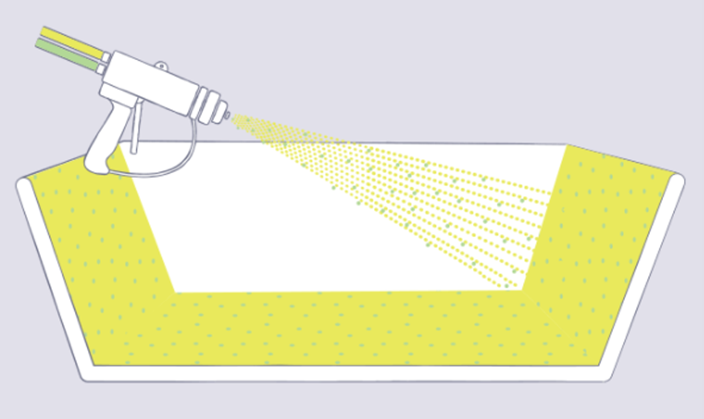
Spray-up, or chopping, is an open mold method similar to hand lay-up in its suitability for making boats, tanks, transportation components, and tub/shower units in a large variety of shapes and sizes. A chopped laminate has good conformability and is sometimes faster to produce than a part made with hand lay-up when molding complex shapes.
In the spray-up process, the operator controls thickness and consistency, therefore the process is more operator dependent than hand lay-up. Although production volume per mold is low, it is feasible to produce substantial production quantities using multiple molds. This process uses simple, low-cost tooling and simple processing. Portable equipment permits on-site fabrication with virtually no part size limitations. The process may be automated.
Process:
As with hand lay-up, gel coat is first applied to the mold and allowed to cure. Continuous strand glass roving and initiated resin are then fed through a chopper gun, which deposits the resin-saturated “chop” on the mold. The laminate is then rolled to thoroughly saturate the glass strands and compact the chop. Additional layers of chop laminate are added as required for thickness. Roll stock reinforcements, such as woven roving or knitted fabrics, can be used in conjunction with the chopped laminates. Core materials of the same variety as used in hand lay-up are easily incorporated.
Molds:
These are the same molds as hand lay-up: simple, single cavity molds of fiberglass composites construction. Molds can range from small to very large and are low cost in the spectrum of composites molds.
Q9) Explain in detail Filament winding process.
A9) Filament winding process:
Composites have proved to be a worthy alternative to other conventional materials even in the high - pressure situations of chemical processing. Besides higher corrosion resistance, composite materials demonstrate good resistance to extreme temperatures, particularly in industrial settings.
The modification ability of composites for precise applications has been one of its advantages. The larger industry has now begun to acknowledge that these composites assure to offer tremendous business opportunities in an array of application.
Manufacturing Techniques
The end properties of a composite part are not only dependent upon the properties of fibre & resin matrix, but also depended on the way by which they are developed. There are ranges of processing techniques for fabricating composite parts or structures like resin transfer moulding (RTM), autoclave moulding, pultrusion and filament winding.
Out of these processes, filament winding is a cost-effective and efficient technique for manufacturing of fibre toughened cylindrical components and high-pressure pipes.
Process Technology
A large number of fibre roving’s is pulled from series of creels into bath containing liquid resin, catalyst and other ingredients such as pigments and UV retardants. Fibre tension is controlled by the guides or scissor bars positioned between each creel and resin bath. Just before entering the resin bath, the rovings are usually gathered into a band by passing them through a textile thread board or stainless-steel comb. At the end of the resin tank, the resin-impregnated rovings are pulled through a wiping device that removes the surplus resin from the rovings and controls the resin coating thickness around each roving.
The most commonly used wiping device is a set of squeeze rollers in which the position of the top roller is accustomed to control the resin content as well as the tension in fibre rovings. Another technique for wiping the resin-impregnated rovings is to pull each roving separately through an orifice. The concluding method results in better control of resin content. Once the rovings have been meticulously impregnated and wiped, they are gathered together in a flat band and situated on the mandrel.
Band formation can be achieved by passing through a stainless-steel comb and later through the collecting eye. The transverse speed of the carriage and the winding speed of the mandrel are controlled to create the required winding angle patterns.
After winding, the filament wound mandrel is subjected to curing and post curing operations during which the mandrel is constantly rotated to maintain uniformity of resin content around the circumference. After curing, product is removed from the mandrel, either by hydraulic or mechanical extractor.
Materials Used
Glass fibre is the fibre most commonly used for filament winding, carbon and aramid fibres are also used. Most high strength critical aerospace structures are produced with epoxy or polyurethane resins, with epoxy, polyurethane or cheaper polyester resins being specified for most other applications. The ability to use continuous strengthening without any breaks or joins is a definite advantage, as is the high fibre volume fraction that is accessible, about 60% to 80%. Only the inner surface of a filament wound structure will be smooth except a secondary operation is performed on the outer surface. The component is generally cured at high temperature before removing the mandrel. Finishing operations such as machining or grinding are normally not required.
Q10) Explain in detail Resin transfer moulding.
A10) Resin Transfer Moulding:
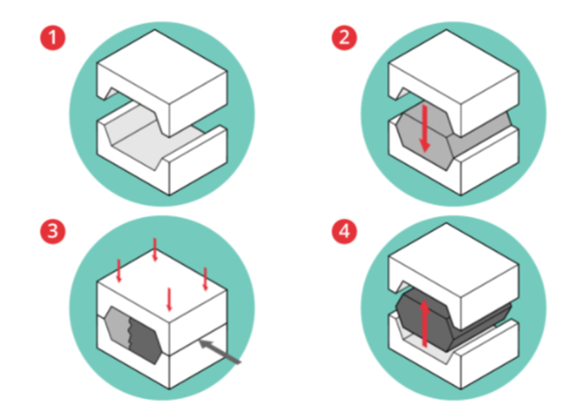
Resin transfer moulding (RTM) is a closed-mould process for manufacturing high performance composite components in medium volumes (1,000s to 10,000s of parts). Moulds typically consist of matched metal tools into which a dry fibre preform is inserted 1. The mould is then closed 2 and clamped shut before pumping resin into the tool cavity to thoroughly wet-out the fibres 3. The tool will often be heated to assist with the curing of the resin. Once the resin is cured, the tool can be opened and the part removed 4.
Process Strengths
Process Limitations
Q11 What is Pultrusion.
A11) Pultrusion:
The Pultrusion process is a highly automated continuous fibre laminating process producing high fibre volume profiles with a constant cross section. Having a high fibre volume fraction makes pultrusion an ideal process for structural component production giving a high strength to weight ratio.
The process starts with the support of the reinforcements. These can be glass, carbon or aramid and in a roving/tow, mat, woven or stitched format. The material is pulled into the infeed area where it is accurately formed to the required shape and impregnated with a resin matrix. The resin matrix can be polyester, vinylester, epoxy or phenolic. From the infeed area the impregnated reinforcement is pulled into the heated pultrusion die. The resin matrix is such that it solidifies and cures within the die. The cured profile exiting the die is allowed to cool before being clamped and pulled by the reciprocating puller units. The puller units reciprocate in a hand over hand motion, with the return stroke being faster than the pulling stroke to give a smooth continuous pull at a constant speed irrespective of the pulling force required. From the puller units the profile passes into the flying cut off saw where it is cut to the required length.
Q12) Explain in detail compression moulding process.
A12) Compression moulding process:
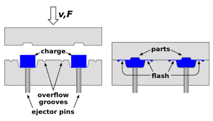
Compression Molding is a molding method in which the molding material (especially Thermoplastics or Thermoset plastics) is generally preheated and is placed in a mold cavity. The heating or cooling given to the cavity depends upon the type of plastic used.
The below diagram represents Compression Molding Process for both Thermoplastics as well as Thermoset Plastics.
Compression Molding Process Working Principle:
The working principle of Compression Molding process is as follows.
It is used for both thermoplastics and thermosetting plastics, but I can classify them under two cases and they are as follows.
Case 1: For Thermosetting Plastics
Case 2: For Thermoplastics
Q13 State advantages and disadvantages of molding process.
A13) Advantages of Compression Molding Process:
Disadvantages of Compression Molding Process:
Q14) Explain Vacuum impregnation process.
A14) Vacuum impregnation process:
Vacuum impregnation in metal castings and powdered metal parts refers to the sealing of leaks resulting from porosity. In this post, we will discuss in detail one of the selection variables, the three different types of vacuum impregnation processes.
In general, all vacuum impregnation process types follow the same four steps:
The impregnation process type is defined by the first step, which will largely determine if the castings are sealed. The subsequent steps will have a greater impact on assembly characteristics than on sealing performance. Armed with this understanding, the three commercially viable impregnation process types are:
Dry Vacuum and Pressure (DVP)
Dry Vacuum (DV)
Wet Vacuum (WV)
The 4 Steps to the Vacuum Impregnation Process
Vacuum impregnation seals porosity and leak paths that form during the casting or molding process. Vacuum impregnation stops casting porosity and allows manufacturers to use parts that would otherwise be scrapped. Read the following four steps to learn how porosity can be sealed through the vacuum impregnation process.
Beginning Part
Porosity in Casting
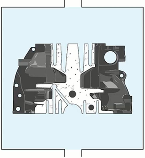
The porosity of the cross section of this part is shown as the black squiggly lines.
The porosity will cause:
-Pitting or blemishes on the surface
-Inability to hold fluids or gases under pressure
-Corrosion results from fluids penetrating the pores.
Step 1
Casting in vacuum impregnation chamber
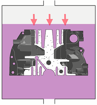
In the impregnation chamber (also known as an autoclave, pressure vessel or vacuum vessel) air is evacuated from the leak path in the part by using a deep vacuum. The evacuated leak path is filled with sealant by covering the part with the sealant and applying pressure. More energy is required to penetrate the porosity with sealant than to evacuate the air.
Step 2
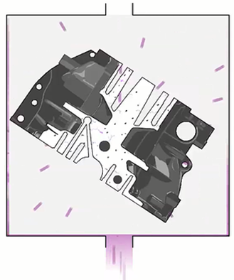
In the recovery station (also known as drain station, centrifuge) excess sealant is recovered for reuse.
Step 3
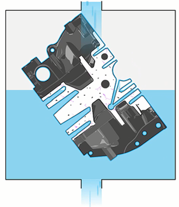
In the wash/rinse station (also known as surge station, rolling rinse or pump over station) residual sealant is washed from the part’s internal passages, taps, pockets and features where sealant is undesirable.
Step 4
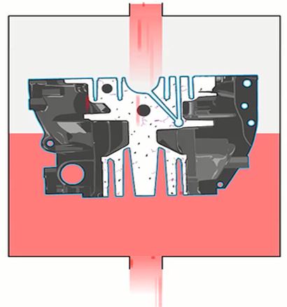
In the cure station (also known as standing, rolling cure or pump over station) the sealant, impregnated into the walls of the part, is polymerized in the leak path.
Final Part
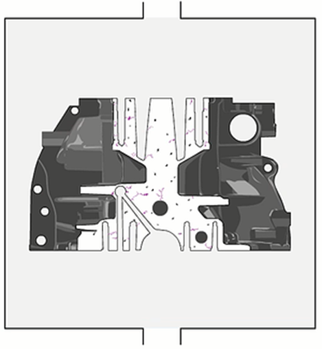
As shown in purple, the porosity is fully sealed without changing dimensional or functional characteristics.
Q15) Define Processing of metal matrix composites and explain one state of processing.
A15) Processing of metal matrix composites:
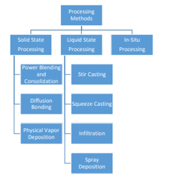
Processing of metal matrix composites (MMC) can be classified into three main categories:
- Solid State Processing
- Liquid State Processing
- In-Situ Processing
1. Solid State Processing
The main fabrication methods for solid state processing of metal matrix composites are powder blending and consolidation, and physical vapor deposition.
a) Powder Blending and Consolidation:
Metal alloy powder is blended with ceramic whisker/short fiber/particles in dry condition or in liquid suspension. After blending, the mixture is further processed by cold compaction, canning, degassing, and high temperature consolidation. There are some oxide particles in volume fraction of 0.05-0.5 depending on the powder and processing conditions that help Processing Methods Solid State Processing Power Blending and Consolidation Diffusion Bonding Physical Vapor Deposition Liquid State Processing Stir Casting Squeeze Casting Infiltration Spray Deposition In-Situ Processing 7 dispersion-strengthening of the metal matrix composites. This method is usually used for the processing of aluminum and magnesium metal matrix composites.
b) Diffusion Bonding:
The inter diffusion atoms at the metallic surfaces under pressure creates bonding between the metal matrix and fiber. This fabrication method is widely used for aluminum or magnesium MMCs reinforced with continuous/discontinuous fibers.
c) Physical Vapor Deposition: Fibers are continuously passed through a region of high partial pressure of metal to be deposited. The vapor is produced and inserted in the process, then the condensation occurs at this region to produce a coating on the fiber. The rate of deposition is about 5-10 micrometer per minute. The coated fibers are then consolidated by hot pressing or hot isostatic pressing.
Q16) Explain in detail Liquid state processing and In-Situ Processing.
A16) Liquid State Processing
a) Stir Casting:
Particulate reinforcements are mixed with liquid metal melt and the mixture then solidifies. Specifically, the pre-treated particles are inserted into the vortex of molten alloy, which is created by a rotating impeller. A problem arises during the stir casting process as the reinforcements are not uniformly distributed and form sediments in the molten alloy. Generally, up to 30% particles in the size of 5-100 micrometer can be incorporated into the metal alloy. An example of this method is Al-(10-15%) B4C MMCs. In another variant of the stir casting method, particles are introduced into the metal alloy in the semi-solid state.
b) Squeeze Casting
Molten metal is introduced into an open die. The dies are then closed so that the molten metal solidifies under pressure within the dies. The heat is rapidly transferred from the molten metal to the dies under high pressure and through the contact between the metal and the die surface. As a result, a fine-grain casting with little to no pore is produced using this method.
c) Infiltration Process:
Liquid metal alloy is infiltrated into the porous forms of fibers/whiskers reinforcements. The volume fraction of the reinforcements usually ranges from 10-70%, depending on the level of porosity. Silica and metal-based mixtures are often employed as binder to retain the integrity and shape of the porous forms.
d) Spray Deposition
Particle/whisker/short fiber reinforcements are injected into the spray, creating a deposition layer of porosity of 5-10% on the metal surface. The depositions are then consolidated to full density by further processing [9]. For continuous (long) fiber reinforced metal matrix composites, matrix metals are sprayed onto the fibers. The fiber spacing and fiber layer in this processing method impact the fiber volume fraction and distribution.
3. In-Situ Processing
In-situ processing involves chemical reactions that result in the creation of reinforcing phase within a metal matrix. The reinforcements can be formed from the precipitation in liquid or solid. This method provides thermodynamic compatibility at the matrix reinforcement interface. The reinforcement surfaces are also likely to be free of contamination and, therefore, a stronger matrix-dispersion bond can be achieved.
Q17) Explain Fabrication of Ceramic Matrix Composites by Direct Oxidation.
A17) Process Direct Metal Oxidation (DIMOX) - description
Direct metal oxidation process (Dimox) of Ceramic Matrix Composites fabrication is a type of Reactive Melt Infiltration (RMI) technique, involving a formation of the matrix in the reaction of a molten metal with an oxidizing gas.
Preform of dispersed phase (fibers, particles) is placed on the surface of parent molten metal in an atmosphere of oxidizing agent (Oxygen).
Two conditions are necessary for conducting Direct oxidation process: dispersed phase is wetted by the melt; dispersed phase does not oxidize in an atmosphere of oxygen.
Liquid metal oxidizes when it is in contact with oxygen, forming a thin layer of ceramic with some dispersed phase incorporated in it.
Capillary effect forces the melt to penetrate through the porous ceramic layer to the reaction front where the metal reacts with the gas resulting in growing the ceramic matrix layer.
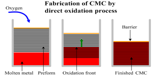
The melt advances to the reaction front continuously at a rate limited by the oxidation reaction rate.
Some residual metal (about 5-15% of the material volume) remains in the inter-granular spaces of the ceramic matrix.
The resulting materials have no pores and impurities, which are usually present in ceramics fabricated by sintering (binders, plasticizers, lubricants, deflocculants, water etc.).
Commonly Direct Melt Oxidation (DIMOX) technique is used for fabrication composites with the matrix from aluminum oxide (Al2O3). A reinforcing preforms (SiC or Al2O3 in either particulate or fibrous form) is infiltrated with a molten aluminum alloy heated in a furnace to a temperature 1652-2102°F (900-1150°C).
The aluminum alloy is doped with additives (e.g., magnesium, silicon) improving the wettability of the reinforcing phase with the melt and enhancing the oxidation process.
The typical rate of DIMOX process is 0.04-0.06”/hr (1-1.5 mm/hr). In principle the direct oxidation process and the oxide growth may continue even after the reaction front has reached the outer surface of the preform. In this case the aluminum oxide will be deposited over the preform changing its dimensions. In order to prevent an advance of the reaction front beyond the preform surface it is coated with a gas permeable barrier. The ceramic matrix growth stops when the reaction front reaches the barrier.
Q18) Explain Direct Metal Oxidation (DIMOX) process. state its advantages and disadvantages.
A18) Direct Metal Oxidation (DIMOX) process
Advantages and disadvantages of Direct Metal Oxidation (DIMOX) process
Advantages of DIMOX process:
The disadvantages of DIMOX process:
Q19) Explain the concept carbon- carbon composites.
A19) Carbon-carbon composites
Carbon/carbon composites, carbon fiber-reinforced carbon matrix composites, under the Carbon Alloys project have been investigated to develop new starting (parent) materials and new functionalities. Carbon/carbon composites consist of carbon fibers and carbon matrices. However, despite an abundance of research papers, there is a need for high performance carbon fibers to develop high performance carbon/carbon composites. The term ‘carbon fibers’ includes carbon fibers, carbon nanotubes and micro-carbon coils. Carbon matrices can contain fullerenes such as C60, graphite, and composites of carbon with metals. Selected combinations of carbon fibers with carbon matrices produce high performance carbon/carbon composites. Reviews and books on carbon/carbon composites, including applications to nuclear fission and fusion fields, are available.
First, we discuss fundamental research on carbon fibers with high compressive strengths. Carbon coils with new functions have been developed with applications to carbon/carbon composites being investigated. Novel composites containing carbon nanotubes instead of carbon fibers with the C60 fullerene as carbon matrix have been developed and their properties examined.
The mechanical properties and oxidation resistance of carbon/carbon composites which control the microstructures of the interfaces between carbon fiber and carbon matrix have received attention. The additions of copper and small amounts of titanium to carbon/carbon composites are effective in increasing thermal conductivities compared with conventional carbon/carbon composites. Fracture mechanisms in carbon/carbon composites have been examined theoretically making use of various material parameters. Microstructures of interfaces between carbon fibers, carbon matrices and impregnated metals have been studied by transmission electron microscopy.
Availability of carbon fibres in the late 1950s led to development of improved materials now known as carbon-carbon (C/C) composites. These composites are a family of materials which consist of a carbon (or graphite) matrix reinforced with carbon (or graphite) fibres. Thus, the attractive properties of carbon are combined with the high strength, versatility and toughness of composites. The C/C family is unique in that it is the only elemental composite.
Carbon-carbon composites range from simple unidirectional fibre reinforced structures to complex woven 3-dimensional structures. The variety of carbon fibres and multidirectional weaving techniques now available allow tailoring of C/C composites to meet complex design requirements. By selection of fibre-type, lay-up (or fibre-weave), matrix and composite heat treatment, the properties can be suited to different applications.
In the early 1960s, carbon-carbon composites were developed for elevated temperature aerospace applications such as nose cones and rocket nozzles. These composites can be tailored to higher strengths and stiffness than other engineering metallic alloys and, unlike metals, can maintain these properties to high temperatures as indicated in Figure 1.
However, the fabrication costs for these materials are high and this has limited their use to primarily aerospace and military applications at present. Therefore, reduction in costs will be achieved by an improvement in the carbon yield. An increase in pressure from ambient, where a 50% carbon yield is achieved, to 100MPa improves the carbon yield to 90%. This is the basis of high-pressure carbonisation and pyrolysis, a technique being investigated by TWI and others.
Q20) Explain the concept Polymer matrix.
A20) Polymer Matrix:
Polymer matrix composites (PMCs) are present in almost all aspects of modern life - from gadget components to a vast selection of automotive accessories. Derived from its name, meaning many repeating units, polymers are often made up of branches of carbon and hydrogen chemically linked together to make a chain.
Polymers that are often used as composites are either thermoplastic polymers, thermosetting polymers or elastomers. They are a source of a wide variety of low-priced, raw materials which offer many advantages like
Yet, they suffer from some deficiencies as in strength and stiffness. To make up for those deficiencies, reinforcements are integrated into polymer materials to enhance their mechanical properties.
What is a polymer matrix composite?
Polymer matrix composites are materials made up of fibres that are embedded in an organic polymer matrix. These fibres are introduced to enhance selected properties of the material.
Polymer matrix composites are classified based on their level of strength and stiffness into two distinct types:
Properties of a PMC
The constituents of a PMC, which affect its overall properties, are [3]:
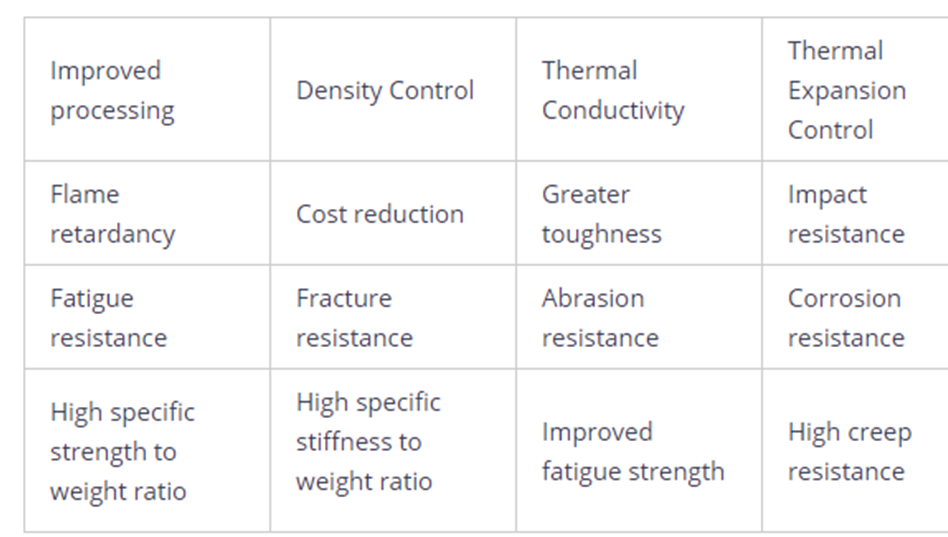
The main advantages of polymer matrix composite materials are their strength and stiffness. Other qualities that come with the reinforcement of polymers are as follows
Production of polymer matrix composites
Polymers are reinforced with fibres which are 8 to 12 μm in diameter either as continuous single or chopped multi-filaments that are woven into cloth and other types of preformed textiles. These fibres are then impregnated into the matrix polymer in liquid form by injection, extrusion, pressing or stamping and then cured to produce the final composite.
During the fabrication and shaping of polymer matrix composites into finished products, often the formation of the material itself is incorporated in the fabrication process. These processes include:
What is a PMC used for?
PMCs are regarded due to their low cost and straightforward fabrication methods. Applications for PMCs include
Automotive industry - Body panels, leaf springs, driveshaft, bumpers, doors, racing car bodies, and so on.
Aircraft and aerospace industry - Used in the construction of structural parts for military aircraft, space shuttles, and satellite systems. The main purposes of using PMCs are to reduce aircraft weight, which can improve its performance, and to reduce its costs.
Marine - Fibreglass boat bodies, as well as canoes and kayaks.
Sports goods - Used in performance footwear, sports equipment and other sporting goods because of their lightweight and high-strength properties.
Biomedical applications - Medical implants, orthopedic devices, MRI scanners, X-ray tables, and prosthetics.
Electrical - Panels, housing, switchgear, insulators, and connectors. It also covers electronic devices like capacitors, Li-ion and flexible batteries and covers for digital portable equipment like headphones, etc.
Protective equipment - Since polymer matrix composites can withstand extreme hot or cold and other hazardous conditions, they are often made as raw materials for bulletproof vests and other armour.
Industrial - Chemical storage tanks, pressure vessels, pump housing, and valves. PMCs are also used in impellers, blades, blower and pump housings, and motor covers.
Structural - Polymer matrix composites are used to repair bridges and other construction materials and equipment like booms and cranes.
Q21) Explain Nano-composites.
A21) Nano-composites
Background
Nanocomposites are materials that incorporate nanosized particles into a matrix of standard material. The result of the addition of nanoparticles is a drastic improvement in properties that can include mechanical strength, toughness and electrical or thermal conductivity. The effectiveness of the nanoparticles is such that the amount of material added is normally only between 0.5 and 5% by weight.
Improved Properties
Nanocomposites can dramatically improve properties like:
• Mechanical properties including strength, modulus and dimensional stability
• Electrical conductivity
• Decreased gas, water and hydrocarbon permeability
• Flame retardancy
• Thermal stability
• Chemical resistance
• Surface appearance
• Optical clarity
How Nanocomposites Work
Nanoparticles have an extremely high surface to volume ratio which dramatically changes their properties when compared with their bulk sized equivalents. It also changes the way in which the nanoparticles bond with the bulk material. The result is that the composite can be many times improved with respect to the component parts. Some nanocomposite materials have been shown to be 1000 times tougher than the bulk component materials.
Applications
Nanocomposites are currently being used in a number of fields and new applications are being continuously developed. Applications for nanocomposites include:
• Thin-film capacitors for computer chips
• Solid polymer electrolytes for batteries.
• Automotive engine parts and fuel tanks
• Impellers and blades
• Oxygen and gas barriers
• Food packaging.