Unit - 5
Threaded joints and Welded joints
Q1) Explain bolt of uniform strength with neat sketch.
A1)
- Resilience of the bolt is important design consideration to prevent breakage at the threads.
- Resilience is defined as the ability of the material to absorb energy when deformed elastically and to release this energy when unloaded.
- It can be shown that the energy absorbed during elastic deformation is proportional to the square of the stress induced in the material and the volume of the material under the stress.
- Fig. (a) shows ordinary Bolt with usual shape.
- The major diameter of the thread as well as the diameter of the shank is 'd'.
- The core diameter of the threads is
 .
. - When this bolt is subjected to tensile force, there are two distinct regions of stress. They are as follows
- The diameter of threaded portion
 is less than shank diameter 'd'.
 - The threaded portion is also subjected to stress concentration.
- Therefore, stress-induced in threaded portion is more than the stress in the shank portion.
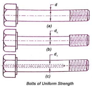
- The energy absorbed by each unit volume of bolt material is proportional to the square of the stress.
- Hence, a large part of the energy is absorbed in the threaded portion of the Bolt.
- The diameter of the shank is more than the core diameter of the threaded portion. There is no stress concentration in the shank.
- Therefore, when the bolt is subjected to tensile force, the stress in the shank portion is less than the stress in the threaded portion.
- The energy absorbed in the shank, which is proportional to the square of the stress, is less than the energy absorbed in the threaded part.
- The shock absorbing capacity of bolt can be increased if the shank of the bolt is turned down to a diameter equal to the root diameter of the threads or even less.
- In this case, the shank is subjected to higher stress and hence absorbs a greater proportion of strain energy and relieves the threaded portion of high stress.
- The resilience of the bolt can also be increased by increasing its length.
- The strain energy absorbed by the shank is linearly proportional to its length.
- Therefore, there are two methods of increasing the shock absorbing capacity of bolt. They are as follows:
(i)Reduces the shank diameter to core diameter of threads or even less.
(ii) Increase the length of shank portion of bolt.
- The ideal Bolt will be one, which is subjected to same stress level at different cross-sections in the Bolt.
- It is called the Bolt of uniform strength. In Bolt of uniform strength, the entire bolt is stressed to the same limiting value, thus resulting in maximum energy absorption.
- There are two ways to reduce the cross-sectional area of shank and convert ordinary Bolt into a Bolt of uniform strength.
- They are illustrated in figure (b) and (c).
- One method is to reduce the diameter of the shank as shown in figure (b).
- In another method, the cross-sectional area of the shank is reduced by drilling a hole, as illustrated in figure (c).
- In first method, the diameter of the shank is usually reduced to the core diameter of the threads. Therefore, the cross-sectional area of the shank is equal to the cross sectional area of the shaded portion.
- When this bolt is subjected to tensile force, the stress in the shank and the stress in the threaded portion are equal.
- In second method, the diameter of the hole
 is obtained by equating the cross-sectional area of the shank to that of threaded part. Therefore,

Where, d= nominal or major diameter of the bolt
 core or minor diameter of the threads.
 diameter of the hole
Q2) Write the procedure to find size of the bolts subjected to eccentric load perpendicular to the axis of the bolts.
A2)
Eccentric Load Perpendicular to Axis of bolt
- A bracket, fixed to the Steel structure by means of four bolts is shown in figure (a).
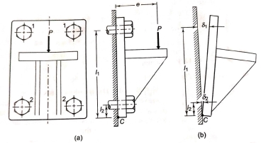
- It is subjected to eccentric force P at a distance e from the structure.
- The force P is perpendicular to the axis of each bolt.
- The lower two bolts are denoted by 2 while the upper two bolts by 1.
- The force P results in direct shear force on the bolts.
- Since the bolts are identical, the shear force on each bolt is given by,
 …… 1
…… 1
- The moment (P × e) tends to tilt the bracket about the edge C.
- As shown in figure (b), each bolt is stretched by an amount
 which is proportional to its vertical distance from the point C. Or,

- The resisting force induced in any Bolt, due to the tendency of the bracket to tilt under the moment (P × e), is proportional to its distance from the tilting edge.
- If
 are the resisting forces induced in the bolts,

 ……. (a)
Where C is constant of proportionality.
Equating the moment due to resisting forces with the moment due to external force P about edge C,

Substituting (a) in (b)

From (a) and (c),
 …….. 2
- The bolts denoted by 1 are subjected to maximum force.
- In general, A Bolt, which is located at the farthest distance from the tilting edge C is subjected to maximum force.
- Equations 1 and 2 give shear and tensile forces that act on the Bolt due to eccentric load perpendicular to the axis of the bolts.
- The direct shear stress in the bolt is given by

- The tensile stress in the bolt is given by

Where A is the cross sectional area of the Bolt at minor or core diameter.
- The bolts can be designed on the basis of principal stress theory or principal shear stress theory.
- The principal stress
 is given by

- The principal shear stress is given by

- Using following relationships, the cross sectional area of bolts and its size can be determined.

Q3) Write the procedure to find size of the bolts subjected to eccentric load parallel to the axis of the bolts.
A3)
- A bracket, fixed to the Steel structure by means of four bolts is shown in figure (a).
- It is subjected to eccentric force P.
- The force P is parallel to the axis of each bolt.
- The force P results in direct tensile force on the bolts.
- Since the bolts are identical, the tensional force on each bolt is given by,
 …… 1
…… 1
- The moment (P × l) tends to tilt the bracket about the edge C.
- As shown in figure (b), each bolt is stretched by an amount
 which is proportional to its horizontal distance from the point C. Or,

- The resisting force induced in any Bolt, due to the tendency of the bracket to tilt under the moment (P × l), is proportional to its distance from the tilting edge.
- If
 are the resisting forces induced in the bolts,

 ……. (a)
Where C is constant of proportionality.
- Equating the moment due to resisting forces with the moment due to external force P about edge C,

Substituting (a) in (b)

From (a) and (c),
 …….. 2
- The bolts denoted by B are subjected to maximum force.
- In general, a Bolt, which is located at the farthest distance from the tilting edge C is subjected to maximum force.
- Equations 1 and 2 give tensile forces that act on the Bolt due to eccentric load parallel to the axis of the bolts.
- Therefore, resultant tensile force is given by

- The tensile stress in the bolt is given by

Where A is the cross sectional area of the Bolt at minor or core diameter.
- Using following relationships, the cross sectional area of bolts and its size can be determined.

Q4) Write the procedure to find size of the bolts subjected to eccentric load on circular base.
A4)
- A round flange bearing fastened by means of four bolts is shown in figure (b).
- It is subjected to external force P at a distance l from the support.

- As shown in figure (a), when the load tense to tilt the bearing about point C, each bolt is stretched by an amount
 , which is proportional to its vertical distance from the point C. Or,
 and so on.
- The resisting force acting on any Bolt due to the tendency of the bearing to tilt is proportional to its distance from the tilting edge.
If  are the resisting forces induced in the bolts


Where C is the constant of proportionality.
- Equating the moment due to external force P about C with moments due to resisting forces,

From (a) and (b),


From (a) and (c), the force acting on Bolt 1 is given by

Suppose, a = radius of the flange
b= radius of pitch circle of the bolts
From figure (b)


Therefore, 


=4a2+2b2 (cos2 α+sin2 α)
Or,  ……. (e)
From (d) and (e) 
Multiplying the numerator and denominator of right-hand side by 2

- Four bolts are considered in above analysis.
- If the procedure is repeated for n equally spaced bolts, we get the general expression in the following form

- The force
 has maximum value when the term
  has minimum value.
 - The minimum value of
 is (-1), when
  .
. - With reference to figure (b), the Bolt 1 will occupy the topmost position, at the farthest distance from C, when
 , substituting
  in above equation

- Above equation gives absolute maximum value of the force acting on any of the bolts.
- It should be used for finding out the size of the boats, when the direction of external force P can change with respect to the bolts, as in case of the base of a vertical pillar crane.
- When the direction of external force P is fixed and known, the maximum load on the bolts can be reduced so that two of them can be equally stressed as shown in figure (c).
- In this particular case, the number of bolts is 4 and angle made by the centre line of bolt 2 is 135°.
- For a general case with n number of bolts,


Therefore,

Substituting above value of  in equation 1,

- The above equation is applicable only when two bolts are equally stressed.
Q5) Derive expression to determine strength of butt weld.
A5)
Strength of Butt Wields
- A butt welded joint, subjected to tensile force P is shown in figure.
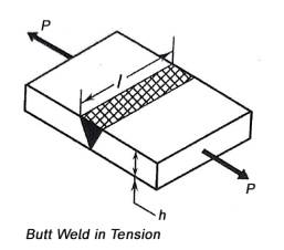
- The average tensile stress in the weld is given by,

Where,  =tensile stress in the weld (N/m
P = tensile force on the plates (N)
h = throat of the butt weld (mm)
l = length of the weld (mm)
- Equating the throat of the weld 'h' to the plate thickness 't' in equation 1, the strength equation of butt joint can be written as
P=σt t l (2)
Where, P= tensile force on plates (N)
 = Permissible tensile stress for the weld (N/m
t = thickness on the plate (mm)
- There are certain codes, like code for unfired pressure vessels, which suggest reduction in strength of butt welded joint by a factor called efficiency of the joint. Where the strength is to be reduced, equation 2 is modified and rewritten in the following way

Where, = efficiency of the welded joint (in fraction)
- Butt welded joint, when properly made, has equal or better strength than the plates and there is no need for determining the stresses in the weld or the size and the length of the weld.
- All that is required is to match the strength of the weld material to the strength of the plates.
Q6) Derive expression to determine strength of parallel fillet weld.
A6)
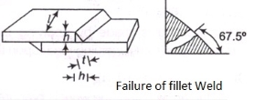
- A parallel Fillet weld subjected to tensile force P is shown in figure (a).
- The enlarged view of fillet weld is shown in figure (c).
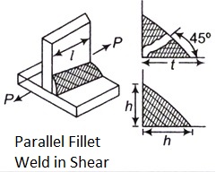
- There are two terms related to the dimensions of the fillet weld leg h and throat t.
- The size of the weld is specified by the leg length.
- The cross section of the fillet weld consists of a right-angle triangle having two equal sides.
- The length of each of the two equal sides is called leg.
- As a rule, the leg length h is equal to the plate thickness.
- The throat is the minimum cross section of the weld located at 45 degree to the leg dimension. Therefore

- Failure of the fillet weld occurs due to shear along the minimum cross section at the throat.
- The shear failure of the weld is shown in figure (b).
- The cross sectional area at the throat is (t l) or (0.707 hl).
- The shear stress in the fillet weld is given by

Rearranging the terms of equation 2, the strength equation of the parallel fillet weld is written in the following form
P=0.707 h l τ (3)
Where,
P = tensile force on plates (N)
h = leg of the weld (mm)
l = length of the weld (mm)
 = Permissible shear stress of the weld N/m
- Usually, there are two welds of equal length on two sides of the vertical plate. In that case,

- In determining the required length of the weld 15mm should be added to the length of each weld calculated by equation 3 and 4 to allow for starting and stopping of the weld run.
- In case of static load, the permissible shear stress for the fillet weld it is taken as 94 N/m
 as per the code of American Welding society (A.W.S).
Q7) Derive expression to determine strength of transverse fillet weld.
A7)
- A transverse fillet welds subjected in tensile force P is shown in figure (a).
- The transverse fillet welds are subjected to tensile stress.
- The minimum cross section of the weld is at the throat.
- Therefore, the failure due to tensile stress will occur at the throat section.
- The cross sectional area at the throat is (tl).
- The tensile stress in the transverse fillet weld is given by


Rearranging the terms of equation 1, the strength equation of the transverse fillet weld is written in the following form

Where,  = permissible tensile stress for the weld N/m
- Usually, there are two welds of equal length on two sides of the plate as shown in figure (a). In such cases


- The nature of stresses in the cross section of the transverse fillet weld is complex.
- The weld is subjected to normal stress as well as shear stress.
- In addition, the throat is subjected to bending moment.
- In order to simplify the design of fillet welds, many times shear failure is used as the failure criterion.
- It is assumed that the stress in the transverse fillet weld is shear stress on the throat area for any direction of applied load.
Q8) Derive expression to determine strength of axially loaded unsymmetrical welded joint.
A8)
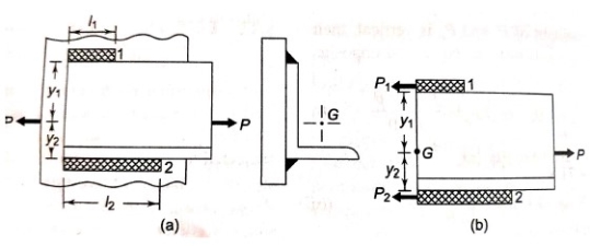
- In certain applications, unsymmetrical section such as angle or T are welded to the steel plate for the beams.
- Figure (a) shows an angle section welded to a vertical beam by means of two parallel fillet welds 1 and 2.
- G is the centre of gravity of the angle section.
- The external force acting on the joint passes through G.
- Suppose
 are the resisting forces set up in the welds 1 and 2 respectively.

 (b)
(b)
- The free body diagram of forces acting on the angle section with two variants is shown in figure (b).
- Since the sum of horizontal forces is equal to zero.

- Since the moment of forces about the centre of gravity is equal to zero,
 (c)
(c)
Substituting expressions (a) and (b) in expression (c)

Assuming total length of welds as l,
 (2)
(2)
Above equations are used to find out the required lengths  of two welds.
Q9) Explain eccentric load in plane of welds.
A9)
- The design of welded joint subjected to an eccentric load in the plane of welds, consists of calculation of primary and secondary shear stresses.
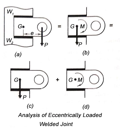
- A bracket subjected to an eccentric force P and attached to the support by means of two fillet welds
 is shown in figure (a).
 - In such problems, the first step is to determine the centre of gravity of welds, treating the weld as a line.
- Suppose G is the centre of gravity of two welds and e is the eccentricity between the centre of gravity and the line of action of force P.
- According to the principal of applied mechanics the eccentric force P can be replaced by an equal and similarly directed force acting through the centre of gravity G, along with the couple (M = P× e) lying in the same plane.
- The effect of force P and couple M are treated separately as shown in figure (c) and (d) respectively.
- The stresses in this welded joint as shown in figure.
- Therefore, force P acting through the centre of gravity causes direct shear stress in the welds (a).
- It is called the primary shear stress. It is assumed that the primary shear stress is uniformly distributed over the throat area of all welds. Therefore,

Where A is the throat area of the welds.
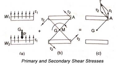
- The couple M causes torsional shear stress on the throat area of welds[figure(b)]. They are called secondary shear stress and given

Where, r = distance of a point in weld
J = polar moment of inertia of all weld
- The secondary shear stress at any point in the weld is proportional to its distance from the centre of gravity. It is maximum at the farthest point such as A.
- The shear stress at any point is obtained by vector addition of primary and secondary shear stresses [fig.(c)].
- Figure shows a weld length l and throat t.
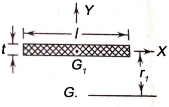
 is the centre of gravity of the weld, while G is the centre of gravity of a group of welds.
 - The moment of inertia of this weld about its centre of gravity G is given by

Since t is very small compared with  is negligible compared with


Therefore,

Where A is the throat area of the weld and  is the polar moment of inertia of the weld about its centre of gravity.
- The polar moment of inertia about its passing through G is determined by the parallel theorem. Thus,

Where  is distance between
  . From above equations

Where there are number of welds, with polar moment of inertia  bout the centre of gravity G, the resultant polar moment of inertia is given by

The above value of G is to be used to determine secondary shear stresses.
Q10) Explain welded joint subjected to bending moment.
A10)
- A cantilever beam of rectangular cross-section is welded to a support by means of two fillet welds
 as shown in figure.
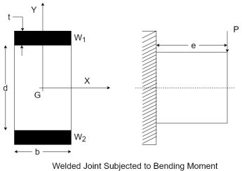
- According to the principal of Applied Mechanics, the eccentric force P can be replaced by an equal and similarly directed force P acting through the plane of welds, along with the couple
 as shown in figure.
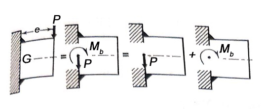
- The force P through the plane of welds causes the primary shear stress
 which is given by

Where A is the throat area of all welds.
- The moment
 causes bending stresses in the welds. The bending stresses are given

Where, I = moment of inertia of all welds based on the throat area
y = distance of the point weld from the neutral axis.
- The bending stresses are assumed to act normal to the throat area.
- The resultant shear stress in the weld is given by

- Referring back to figure and using parallel axis theorem the moment of inertia of weld about the x-axis is given by

- The throat dimension is very small compared to b and d.
- Therefore, the first term in the above expression is neglected.

Since there are two such symmetrical welds,

The above expression should be used in equation 1 to determine the bending stresses.
Q11) Explain welded joint subjected to torsional moment.
A11)
- A shaft of circular cross section is welded to the plate by means of circumferential fillet weld as shown in figure.
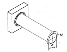
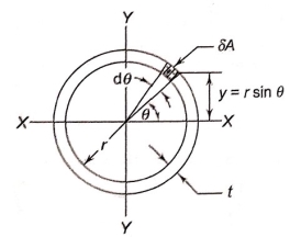
- The shaft is subjected to torsional moment
 that induces torsional shear stresses in the weld.
 - Refer to figure and consider and elemental section in the weld having an area
 .
. - It is located at an angle
 with x-axis and subtends angle
  .
. - The area of the elemental section is given by


- The moment of inertia of annular fillet weld is obtained by integrating the above expression. Therefore,


By symmetry,

The polar moment of inertia is given by


The torsional shear stress in the weld is given by

Q12) A steel plate is fixed to channel by 3 identical bolts. Syt = 380 N/mm ^ 2. Fos 3. Determine size of bolt.
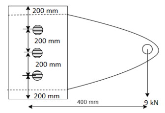
A12)
16 mm


Draw the free body diagram of each bolt
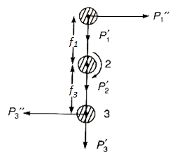
The centre of gravity of the bolts system lies at centre of second bolt.
The force is replaced by a force and couple acting at centre of gravity of the bolt system.
Now primary shear force on each bolt

Now, secondary shear force due to mometn on each bolt


Given 


Total shear force acting on bolt 1


The total shear force on bolt 2=3×
The total shear force on bolt 3

Bolts 1 and 3 are subjected to maximum shear stress


Nominal diameter 
Q13) A steel plate subjected to a force of 8 KN by 2 identical bolts. Syt = 380 N/mm^2 and FOS is 5.
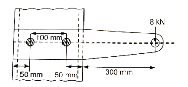
A13)
42 mm


Step 1: First of all, find the centre of gravity of the bolt system and then, distance between centre of bolt and centre of gravity.

Calculate the primary shear force on each bolt

Step 3 Calculate the secondary shear force on each bolt due to moment


Step 4
Now we will draw the free body diagram of the bolts system
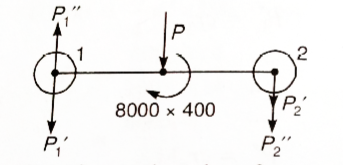
The direction of secondary shear force is in the direction of (moment) couple and perpendicular to radial distances of the bolt centres from the centre of gravity.
We can see from FBD of bolts, system, the maximum shear force subjected to bolt 2.
Step 5:
Calculate the total shear force.
(Maximum value among all the shear forces acting on each bolt.)
The total shear force


Step 6:
Now, we will calculate the bolt diameter.


Nominal diameter=42 mm
Q14) A bolted assembly include a preload of 2.5 KN. External load P acting on the assemble is 5000 N. The bolt has Syt = 400 Mpa & FOS = 5 is taken. The effective stiffness of parts together by bot is 2.5 times the stiffness of bolt. The size of bolt?
A14)
10 mm
Given, 


Nominal diameter =10mm
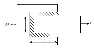
Q15) 85 * 10 mm thick plate is joined by single transverse & double parallel fillet welds to another plate. Max tensile force is 60 KN. Sut & Syt is 70 & 50 N/mm ^2. Length of each parallel fillet.
A15)
50.73
Length of transverse fillet weld =85 mm
Strength of transverse fillet weld + Strength of parallel fillet weld=Strength of the plate
0.707 h 
0.707×10×85×70+1.414×10×50×l’=60×1

Q16) What are benefits of threaded joints?
A16)
i) The components are held together by a strong clamping force. The clamping force is increased due to wedge action at the threads. There has been no loosening of the as a result, threaded joints are dependable joints.
(ii) The parts are assembled with a spanner. The spanner's length is long in comparison to the thread's radius. As a result, the mechanical advantage is greater, and the force required to tighten the joint is minimal.
(iii) Threaded joints have small overall dimensions as a result of their design compacted
(iv) The threads themselves are self-locking. As a result, threaded joints can be installed in any orientation-vertical, horizontal, or inclined.
(v) Threaded fasteners are inexpensive to produce. Their production is straightforward. Threaded components can be manufactured with high precision.
(vi) The threaded joints that connect the parts allow them to be detached as needed. This requirement is required in certain applications for inspection, repair, or replacement.
(vii) Threaded fasteners are standardized, and a wide range is available to suit a variety of operating conditions and applications.
Threaded joints have a number of drawbacks. These are their names: I Threaded joints necessitate the drilling of holes in the machine parts to be clamped. As a result, there is a concentration of stress near the threaded portion of the parts. These areas are prone to fatigue failure.
(ii) When subjected to vibrations, threaded joints loosen.
(iii) Threaded fasteners are regarded as a major impediment to efficient assembly. Tightening a screw in manual assembly can cost six to ten times the cost of the screw itself. As a result, the Design for Manufacture and Assembly (DFMA) standard recommends a minimum number of threaded fasteners.
Q17) Explain Bolt and Screw
A17)
There is a fundamental distinction between a bolt and a screw. A bolt is a fastener with a head and a straight threaded shank that is intended to be used in conjunction with a nut to clamp two or more parts together. When a bolt is threaded into a tapped hole in one of the parts rather than the nut, it is referred to as a screw. Although a bolt and a screw are similar, there is a significant difference in how they are assembled. A bolt is held stationary while torque is applied to the nut to form a threaded joint, and torque is applied to the screw to form matching threads in one of the parts.
Q18) Define & Draw Nut & Define Washers.
A18)
A nut is a small symmetrical part with matching internal threads that is usually hexagonal or square in shape.
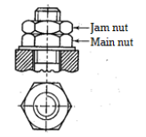
Jam nut
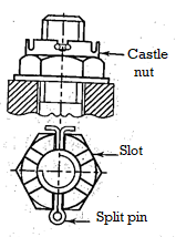
Castle nut
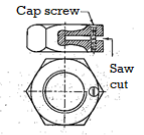
Split nut
Simple washers are thin metallic discs with an annular shape. A washer's functions are to distribute the load over a large area on the surface of the clamped part and to provide a bearing surface over large clearance hole.
Q19) Compare welded vs Riveted joints
A19)
- Riveted joints necessitate the use of additional cover plates, gusset plates, straps, clip angles, and a large number of rivets, all of which add to the weight. Welded assembly results in lightweight construction because there are no such extra parts. Welded steel structures are 50% lighter than corresponding iron castings and 30% lighter than steel castings.
- The cost of welded assembly is lower than that of riveted joints due to the elimination of these components.
- Welded assemblies can be easily and affordably modified to meet changing product requirements. Welding allows for simple changes and additions to the existing structure.
- When compared to riveted assemblies, welded assemblies are more tight and leakproof. Welded assemblies have a shorter production time.
- When two parts are riveted together, holes in the parts are drilled to accommodate the rivets. The holes reduce the cross-sectional area of the members, which causes stress concentration. Welded connections do not have this issue.
- The appearance of a welded structure is smooth and pleasing. The projection of the rivet head has a negative impact on the appearance of the riveted structure.
- The welded joint has a high strength. The strength of the weld is frequently greater than the strength of the plates that are joined together.
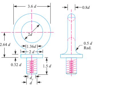
Q20) An eye bolt is to be used for lifting a load of 60 kN. Find the nominal diameter of the bolt, if the tensile stress is not to exceed 100 MPa. Assume coarse threads.
A20)
Given: P = 60 kN = 60 × 103 N; = 100 MPa = 100 N/mm2
An eye bolt for lifting a load is shown in  Fig.11.22
 Nominal diameter of the bolt, and
 Core diameter of the bolt
We know that load on the bolt (P)


We find that the standard core diameter ( is 28.706 mm and the corresponding nominal diameter (d) is 33mm
Q21) Two shafts are connected by means of a flange coupling to transmit torque of 25 N-m. The flanges of the coupling are fastened by four bolts of the same material at a radius of 30 mm. Find the size of the bolts if the allowable shear stress for the bolt material is 30 MPa.
A21)
Given T=25 Nm=25×1 N.mm; n=4;
  ;
; 
We know that the shearing load carried by flange coupling
 (i)
(i)
Let  Core diameter of the bolt
Resisting load on the bolts
 (ii)
(ii)
From equations (i) and (ii) we get

We find that the standard core diameter of the bolt is 3.141 mm and the corresponding size of the bolt is M4.