Unit - 5
Controllers
Q1) The block diagram of a system using PI controllers is shown in the figure. Calculate:
(a). The steady state without and with controller for unit step input?
(b). Determine TF of newly constructed sys. With controller so, that a CL Poles is located at -5?

Fig 1 System with PI controller
A1)
(a). Without:
C(S)/R(S) = 0.2/ (S + 1)
C(S) = R(S) 0.2/ (S + 1) + 0.2
For unit step
Ess = 1/1 + Kp
Kp = lt G(S)
S 0
= lt 0.2/ (S + 1)
S 0
Kp = 0.2
Ess = 1/1.2 = 5/6 = 0.8
(b). With controller:
Gc(S) = Kp + Ki/S
G’(S) = Gc(S). G(S)
= (Kp + Ki/S )0.2/ (S + 1)
= (KpS + Ki)0.2/S (S + 1)
Ess = 1/1 + Kp = 0
So, the value of ess is decreased.
(b). Given
Kpi/Kp = 0.1
G’(S) = (Kp + Ki/S) (0.2/S + 1)
= (KpS + Ki)0.2/S (S + 1)
As a pole is to be added so, we have to examine the CE,
1 + G’(S) = 0
1 + (Kp + Ki)0.2/S (S + 1) = 0
S2 + S + 0.2KpS + 0.2Ki = 0
S2 + (0.2Kp + 1) S + 0.2Ki = 0
Given,
Kpi = 0.1Ki
Kp = 10Ki
S2 + (2Ki + 1) S + 0.2Ki = 0
Pole at S = -5
25 + (2Ki + 1) (-5) + 0.2Ki = 0
-10Ki – 5 + 25 + 0.2Ki = 0
-9.8Ki = -20
Ki = 2.05
Kp = 10Ki
= 20.5
Now,
G’(S) = (KpS + Ki) (0.2)/S (S + 1)
= (20.5S + 2.05) (0.2)/S (S + 1)
G’(S) = 4.1S + 0.41/S (S + 1)
Q2) The block diagram of a system using Pd controller is shown, the PD is used to increase ξ to 0.8. Determine the T.F of controller?

Fig 2 System with PD Controller
A2)
(1). Kp = 1
Without controller:
C(S)/R(S) = 16/S2 + 1.6S + 16
wn = 4
2 ξwn = 16
ξ = 1.6/2 x 4 = 0.2
(b). With derivative:
ξS = 0.2 to 0.8
Undamped to critically damped,
G’(S) = (1 + KdS) (16)/ (S2 + 1.6S)
CE:
S2 + 1.6S + 16(1 + KdS) = 0
S2 + (1.6 + Kd)S + 16 = 0
2 ξwn = 1.6 + Kd1.6
wn = 4
ξS = 0.8
2 x 4 x 0.8 = 1.6 + Kd1.6
6.4 – 1.6 = Kd1.6
4.8/16 = Kd
Kd = 0.3
TF = (1 + 0.3S)16/S (S + 16)
Q3) Explain PID characteristics?
A3)
The manual method for obtaining the characteristics is to set Ki and Kd to zero.
Keeping the values zero we set Kp such that there are oscillations at output. The below figure shows that when Kp is reduced to half the value at which it gave oscillations the output decays.
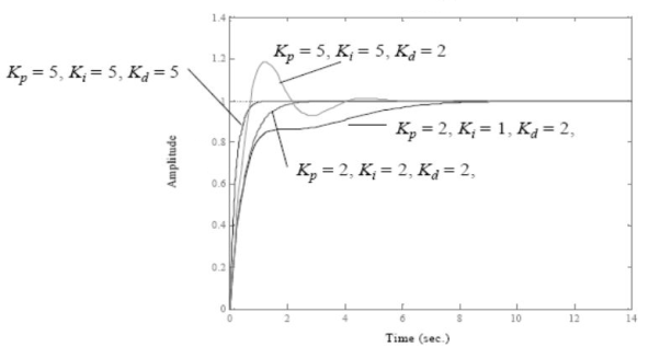
Fig 3 PID characteristics
If Ki is increased the system becomes unstable. So, Ki can be increased to an extent. The value of Kd can be increased so that the output reaches its reference values. If Kd is increased more than it causes overshoot. The system which are overdamped require Kp to be half the value which was making oscillations at output.
Q4) What is the effect of KP, Ki, Kd on performance parameters?
A4)
CL Response | Rise Time | Overshoot | Settling Time | S-S Error |
 | Decrease | Increase | Small Change | Decrease |
 | Decrease | Increase | Increase | Eliminate |
 | Small Change | Decrease | Decrease | Small Change |
Q5) Explain concept of Zeigler-Nicholas Method?
A5)
They proposed the rules for determining values of proportional gain kp, derivative time Td and integral time Ti. They have proposed from (1) methods.
1) First Method: The basic PID controller is shown in figure below. In this method a unit step response of a plant. Is obtained if the plant has neither integrator non dominant complex conjugal poles, then the output step curve is of shape s. As shown below. These curves are generated experimentally.
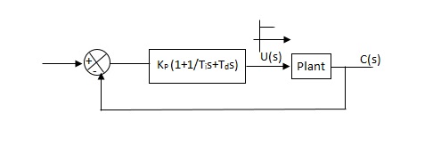
Fig 4 PID Controller
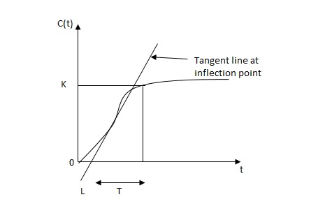
Fig 5 S-Shaped Response Curve
 delay time -L calculated by drawing
Time constant -j tangent
c(s) / l(s) = ke-l1s / ts+1
The values of KP, Ti and td should be set according to the table suggested by Ziegler Nichols tuning rules shown below.
Type of controller
Types of controllers | Kp | Ti | Td |
|
P | T/L | 00 | 0 |
|
PI | 0.9T/L | L/0.3 | 0 |
|
PID | 1.2T/L | 2L | 0.5L |
|
Controller gain Gc(s)= kp(1+1/Tis+Tds)
= 1.2T / L (1+1 / 2LS+0.5 LS)
= 1.2t/l+0.6t / L2S+0.6TS
= 0.6T(2/L+1/L2S+S)
Gc(s) = 0.6 T(S+1/L)2/S
Thus, the PID controller has a pole at the origin and double zeros at S=-1/ L
Second Method -
1) Firstly, set Ti= and Td=0
2) Use proportional control action only, increase kp from 0 to Kcr (Critical value).
3) Then Kcr and pcr (period) are determined experimentally.

Fig 6 Closed loop with proportional controller
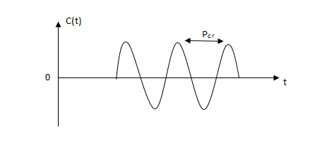
Fig 7 Sustained oscillation with period pcr
4)For this method Ziegler Nichols suggested new set of values for kp, ti and td shown in table below.
Types of controllers | KP | TI | Td |
P | 0.5Kcr |  | 0 |
PI | 0.45 KCR | 1/1.2PCR | 0 |
PID | 0.6KCR | 0.5PCR | 0.125PCR |
|
|
|
|
GC(S) = KP (1.1/Tis+Tds)
=0.6 Kcr(1+1/0.5PcrS+ 0.125 PCRS)
=0.075 KcrPcr(s+4/Pcr)2 / s
Thus, the PID controller has a pole at the origin and double zeros at s= -4/Pcr
Q6) Explain P controllers?
A6)
Effects of controller are viewed on time response and stability.
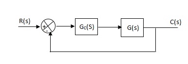
Fig 8 Controller with unity feedback system
Gc(S) = TF of the controller
G(S) = OLTF without controller
G’(S) = Gc(S). G(S)
= OLTF with controller
Proportional means scalar Multiplier.
Gc(S) = Kp Stability can be controlled
Q7) Explain I controllers?
A7)
Integral Controller
The transfer function of this controller is
Gc(S) = Ki/S
Integral controller is used to improve the steady state response or reduce the steady state error.
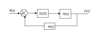
Fig 9 Integral Controller
G’(S) = Gc(S). G(S)
G(S) = 1/S + 5, Gc(S) = Ki/S
G’(S) = Ki/S (S + 5). After applying the Gc(S) the type of system is increasing and hence, the steady state error is decreasing (Refer Time Response).
Disadvantage -
By using integral controller, the stability of closed loop system decreases.
G(S) = 1/S + 5
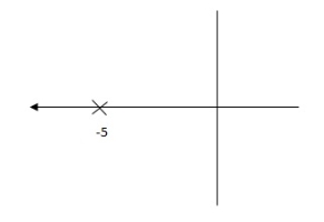
Fig 10 Pole Locations For given system
G’(S) = Ki/S (S + 5)
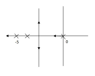
Fig 11 Pole Location after Integral controller
Fig (10), is more stable than (11) as more the away the pole from origin (imaginary axis) more is the stability.
Q8) Explain D controllers?
A8)
Derivative Controller
Gc(S) = Kd(S)
They are used to improve the stability.
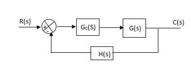
Fig 12 Derivative controller system
G’(S) = KdS/S2(S + 10)
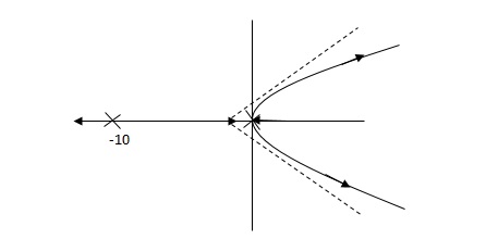
Fig 13 Root Locus for system without controller
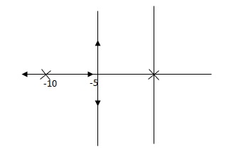
Fig 14 Root locus with controller
Fig 14 is stable i.e., more stable than the Fig 13.
Disadvantage –
It increases the steady state i.e., o/p will not track the input at steady state.
Q9) For system G(S) = 1/S (S + 8) find the system response after P controller is introduced?
A9) CLTF = 1/S2 + 8S + 1
w2n = 1
wn = 1
2ξWn = 8
ξ = 4
ξ>/1 so, overdamped.
Now introducing Gc(S) = K
G’(S) = Kp/S (S + 8)
CLTF = Kp/S2 + 8S + Kp
wn = √Kp
2 ξwn = 8
ξ = 4/√Kp
If,
Kp = 16; ξ = 1; critically damped
Kp> 16; ξ< 1; undamped
Kp< 16; ξ> 1; overdamped
Q10) Explain how we could get control over the system dynamics by use of feedback?
A10)
The dynamics of the system can be controlled by the feedback by adjusting the location of poles. In this section we will see how the location of poles effect the dynamics of the system.
Let us consider a system which has open loop transfer function of G(s) defined as
G(s) =  (1)
(1)
Let K =  /
/
 = 1/
= 1/
The poles for the above system lie at s= - and
and  =1/
=1/ is time constant.
The dc gain of the system is given by G (0) = K =  /
/
For closed loop system the transfer function is given by
 (2)
(2)
 =
= 
 =
=  /(1+K)
The above equation shows that due to feedback the system pole shifts from - to (–
to (– +K’). Due to this change the dynamic response of the system is also affected. For studying the dynamic response, we assume that the input to the system is an impulse.
r(t) =  (t)
(t)
And it can also be written as
R(s) = 1
Taking inverse Laplace transform of equation 1 we get
For open loop system
c(t) = K’
Taking inverse Laplace transform of equation 2 we get
For closed loop system
c(t) = K’
The system dynamic response decays in both the open system as well as closed loop system. The closed loop system time constant is  =
=  /(1+K) so its response decays faster than open loop system by factor of (1+K).
Q11) Explain basic ON-OFF controller?
A11)
The elements which are used to control only two positions either ON or OFF are called as ON-OFF controllers. They do not operate for any other value. In this kind of system, the output will change in process variable. As the output is affected the process variable again changes in reverse direction and at this stage when the process variable exceeds certain limits the output is closed. As the output is closed the process variable will again change in its normal direction and when the pre-set level is crossed the output is open. This process continues making the valve ON-OFF. These are mainly used in electrical power transformer for cooling purpose.
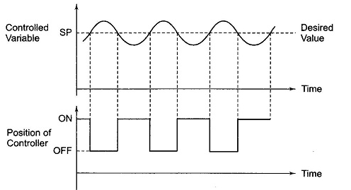
Fig 15 ON-OFF controller
The fan used for cooling the transformer uses these controllers. When the temperature (process variable) is more than the preset value the fan is turned ON and when temperature comes below the preset value the fan is turned OFF. In practical application there is a time lag in the switching of the circuit from ON to OFF and this is defined as dead time. This dead time or delay changes the actual curve of the system.
Q12) Mention need of controller?
A12) The important uses of the controllers include:
- They decrease the steady state error and hence improve the steady-state accuracy.
- The improvement in steady state accuracy results in improvement of system stability.
- Controllers also help in reducing the unwanted offsets produced by the system.
- They also help in controlling the maximum overshoot of the system.
- The noise signals produced by the system are also reduced by using controllers.
- The over damped system has slow response, Controllers helps to improve and increase the response.
Q13) Explain manual tuning of PID controller?
A13) Manual PID tuning is done by setting the reset time to its maximum value and the rate to zero and increasing the gain until the loop oscillates at a constant amplitude. (When the response to an error correction occurs quickly a larger gain can be used. If response is slow a relatively small gain is desirable). Then set the gain of the PID controller to half of that value and adjust the reset time so it corrects for any offset within an acceptable period. Finally, increase the rate of the PID loop until overshoot is minimized.
To tune a PID use the following steps:
- Set all gains to zero.
- Increase the P gain until the response to a disturbance is steady oscillation.
- Increase the D gain until the oscillations go away (i.e., it's critically damped).
- Repeat steps 2 and 3 until increasing the D gain does not stop the oscillations.
- Set P and D to the last stable values.
- Increase the I gain until it brings you to the set point with the number of oscillations desired (normally zero but a quicker response can be had if you don't mind a couple oscillations of overshoot)
Q14) Explain any example of automotive control system?
A14) Automatic control becomes more and more important for the automobile industry. In application areas such as passenger safety, environmental protection and passenger comfort, control functions are implemented in the vehicle electronic control units. In the engine control unit for example, there are several algorithms to reduce emissions, to improve the engine power output and to protect against damage from engine failures.
Compensation of drivetrain oscillations and the adaptive control of automatic gear boxes are examples for applications in the drivetrain area. ABS control, suspension control and vehicle dynamic control increase the driveability of the vehicle and support the driver in dangerous situations. Airbag-systems with automatic recognition of seat occupancy improve passive safety of the passengers in case of an accident. Another large area of control applications are comfort functions like air-condition or navigation systems. Most of these functions require sophisticated signal processing and control algorithms, which are based on models for the system dynamics.
This term is used for the engine and transmission control systems. The engine control unit (ECU) aims to ensure that the engine operates at optimal conditions at all times and includes such items as fuel-injection control, carburettor control, spark-timing control, idle-speed control and anti-knock control. It does this by reading values from many sensors within the engine bay, interpreting the results and then adjusting engine actuators accordingly. Transmission control is primarily involved in automatic transmissions. Often a single engine control unit is used for both engine and transmission control. The engine control unit includes a microcontroller, with the operating software stored in EPROMs or flash memory
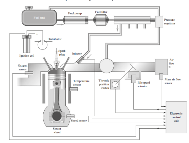
Fig 16 Engine control system
There are a number of control systems in an automobile, and a network is used to communicate information between them. The standard network used to allow microcontrollers and devices to communicate with each other is the controller area network (CAN)
The air–fuel ratio (AFR) is the mass ratio of air to fuel present in an internal combustion engine. If exactly enough air is provided to completely burn all of the fuel, the ratio is known as the stoichiometric mixture. For gasoline fuel, the stoichiometric air–fuel mixture is about 14.7:1 and so, for every 1 g of fuel, 14.7 g of air are required. The air–fuel equivalence ratio, λ (lambda), is the ratio of actual AFR to that at stoichiometry for a given mixture. Thus, if we have λ = 1.0, the mixture is at stoichiometry, for a rich
Mixture λ < 1.0, and for a lean mixture λ > 1.0. The exhaust gas oxygen sensor (EGO) is thus the key sensor in the engine fuel control feedback loop, producing a voltage output that is related to the amount of oxygen in the exhaust. The zirconium dioxide exhaust gas oxygen sensor is widely used. When hot, the zirconium dioxide element produces a voltage that depends on the amount of oxygen in the exhaust compared to that in the outside air. A stoichiometric field mixture gives an output of about 0.45 V, the voltage ranging from about 0.2 V when lean to 0.8 V when rich. The control system used with the lambda sensor is basically a PI controller of essentially a first-order engine system. Figure shows the
Basic system model. The engine can be modelled basically as a first-order system

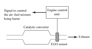
Fig 15 Lambda control circuit
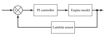
Fig 16 Lambda control system
The PI controller will have a transfer function Gc of KP + KI/s, where KP is the proportional control constant and KI the integral control constant. Thus, taking the lambda sensor to have a transfer function of 1, the closed loop control system will have an overall transfer function T(s) of

However, there is a time delay TL in the lambda sensor responding to a change in oxygen level, typically 50–500 ms, and so to take account of this the transfer function for the engine can be modified by introducing a delay term:
