Unit 5
MECHANICAL POWER TRANSMISSION AND ENERGY CONVERSION DEVICES
QUESTIONS
Question 1) Which material is used in belts of belt drive?
Answer 1) MATERIALS USED FOR BELTS:
The Materials used for belts and ropes must be strong, flexible, and durable. It must have high coefficient of friction: like
1- Leather belts
2- Cotton belts
3- Rubber belts
4- Balata belts
Question 2) Explain Creep in Belts?
Answer 2)
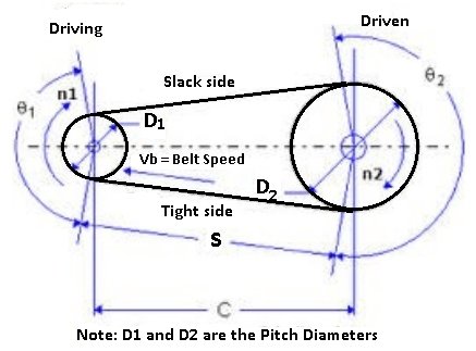
Consider as an open belt drive rotating in the clockwise direction. The portion of the belt leaving the driven and entering the driver is known as the tight side and a portion of the belt leaving the driver and entering the is known as the slack side. During rotation, there is an expansion of a belt on a tight side and contraction of the belt on the slack side.
Due to this uneven expansion and contraction of the belt over the pulleys, there will be a relative movement (motion) of the belt over the pulleys this phenomenon is known as Creep in a belt.
Question 3) Explain Slip in Belts?
Answer 3) Consider an open belt drive rotating in a clockwise direction, this rotating of the belt over the pulleys is assumed to be due to firm frictional grip between the belt and the pulleys.
When this frictional grip becomes insufficient, there is a possibility of forwarding motion of driver without pulley with it, this is known as the slip in a belt.
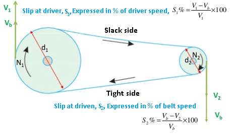
Therefore slip may be defined as the relative motion between the pulley and the belt in it. This reduces the velocity ratio and usually expressed in % and it is denoted by S.
Belt slip is caused due to the following reasons:
(a) Continuous run of the belt, pulley rim surface becomes very smooth,
(b) Decrease in the coefficient of friction in between the two surfaces.
(c) Increase in the length of belt due to constant operation.
(d) Large difference in the tension of the tight side (T1) and the slack side (T2).
Question 4) Explain the difference between belt drive and chain drive?
Answer 4) Belt Drive vs Chain Drive:
Belt Drive | Chain Drive | ||
1) Belt drive is used for transferring the power. | The chain drive is also used for transferring power. | ||
2) The belt drive is powered by only a belt. | The chain drive is powered by a chain loop. | ||
3) Belt drives are made up of synthetic material. This is not stronger as compared to the belt drive. | Chain drives are made up of metal which is stronger and more durable. | ||
4) Belt drives are used in mills. | The chain drive is used in bicycles, motorcycles, and many more engines. | ||
5) In belt drive, little difficulties have when it gets damaged. | It is easier to change or fix when its get damage | ||
6) Low or medium in price | Price is high | ||
7) The belt drive is not the lubricating system | The chain drive is a lubricating system. | ||
8) The belt drive is quieter than the chain drive. | The chain drive is not quittered than a belt drive. | ||
Question 5) What are the different types of chains?
Answer 5)
In the field of Mechanical Engineering chains can be classified into three broad categories and those are:
- Hoisting Chains
-Oval Link Chains
-Stud-Link Chains
2. Conveyor Chains
3. Power transmission Chain
-Block Chain
-Roller Chain
-Silent Chain or Inverted Tooth Chain
Question 6)Write applications of chain drives?
Answer 6)
Applications of chain drives
They are used for power transmission
They are used in transportation industry
They are used in wood working machinery
They are used in agricultural machinery
They are used in oil well drilling rigs
They are used in building construction
They are used in material handling equipment
They are used for lifting load
They are used for carrying materials
Question 7) what are the different materials used to manufacture the gears?
Answer 7) Materials used to manufacture gears:
Tempered steel is one of the most common materials for different types of gears, and aluminium is also common. Other materials used are:
- High strength steels
- Forged stainless steels
- Copper-based alloys
- Cast or forged aluminium alloys
- Cast iron or grey cast iron
- Magnesium alloys
Question 8) what are the applications and utilities of gears?
Answer 8) Applications & Utilities of Gears
The different types of gears are present in many sectors, such as:
- The agricultural sector, in which they play a key role in carrying out mechanized tasks, such as sowing, ploughing or irrigation, as well as in the tractors themselves.
- In the automotive field, their function is usually to act as transmitters of forces and to regulate speed.
- As for naval vehicles, gears operate on fishing boats, submarines, workboats or yachts.
- In the generation of wind power, gears increase the speed of generators, a function that is also used by cement manufacturing industries. Roller mills are used for the transport of slabs and for wire rolling mills.
- In addition, there are four applications of gears that are particularly emblematic, and which are implemented in countless sectors and fields:
Question 9) Describe all the characteristics of gears?
Answer 9)
Characteristics of Gears by Type
Note: If applicable, “A” indicates advantageous characteristics and “D” indicates disadvantageous characteristics | |
Type of Gear | Characteristics |
Spur |
|
Helical |
|
Bevel |
|
Worm |
|
Rack and Pinion |
|
Question 10) What are the parameters we should consider in gear selection process?
Answer 10) Gear Selection Considerations
Gears are employed in a variety of mechanical devices, and, consequently, several different types and designs are available. The suitability of each type of gear and its exact design for a motion or power transmission application is dependent on the specifications and requirements of the application. Some of the principal factors which may be considered when designing and choosing a gear include:
1) Operational and environmental conditions
2) Dimensional restrictions
3) Transmission requirements
4) Design standards
5) Costs
Question 11) Explain the difference between open belts drive and crossed belt drive?
Answer 11) Differences between open belt drive and crossed belt drive
Open Belt Drive | Crossed Belt Drive |
In open belt drive, belt proceeds from top of one pulley to the top of other pulley without crossing. | In crossed belt drive, belt proceeds from top of one pulley to the bottom of other pulley and thus crosses itself. |
In open belt drive, driving shaft and driven shaft rotate in same direction. | In crossed belt drive, driving shaft and driven shaft rotate in opposite direction. |
Contact angle (or wrap angle) between the belt and pulley is comparatively small (always below 180º in smaller pulley). | Contact angle between the belt and pulley is comparatively large (always above 180º in smaller pulley). |
Length of the open belt is smaller as compared to cross belt. | For the same pulley diameter and same centre distance between driver and driven shafts, longer belt is required in cross belt drive. |
Here belt remains in same plane in every rotation during its operation. | Here belt bends in two different planes in every rotation during its operation. |
Here belt does not rub with itself. So belt life is considerably high. | Here belt rubs with itself and thus life of the belt reduces. |
Open belt drive is suitable when driving and driven shafts are in horizontal or little bit inclined. | Cross belt drive can be advantageously applied for horizontal, inclined and vertical positions of driving and driven shafts. |
Power transmission capacity is small due to smaller wrap angle. | It can transmit more power as wrap angle is more. |
Question 12) what are the configurations of centrifugal pumps?
Answer 12) Centrifugal pump configurations
Generally centrifugal pumps are used for high flow low head applications. In order to achieve different sorts of flow the pump can be configured in various ways.
• Pumps in series
• Pumps in parallel
Pumps in series are used for high head requirements. Flow rate remains the same for each pump. Total pressure delivered is the summation of number of pumps that are connected in series.
Pumps in parallel are used for high flow rate applications. Pressure developed is same for each pump. The flow rate produce is the summation of number of pumps that are connected in parallel.
There are several factors that affect the performance of a centrifugal pump. They are
• Working fluid
• Specific gravity of working fluid
• Operating temperature and pressure
• Viscosity
• Net positive suction head
• Vapour pressure of the working fluid
• Cavitation’s
Question 13) Explains the types of centrifugal pumps?
Answer 13) Types of Centrifugal Pumps -Centrifugal Pumps are classified into many types based on many categories, they are:
Based on number of impellers in the pump,
- Single stage pump
- Two-stage pump
- Multi-stage pump
Based on orientation of case-split,
- Axial split Pump
- Radial split Pump
Based on type of impeller design,
- Single suction Pump
- Double suction Pump
Based on the basis compliance with industry standards,
- ANSI pump – (American National Standards Institute)
- API pump – (American Petroleum Institute)
- DIN pump – DIN 24256 specifications
- ISO pump – ISO 2858, 5199 specifications
- Nuclear pump – ASME (American Society of Mechanical Engineers) specifications
Based on type of volute
- Single volute Pump
- Double volute Pump
Based on where the bearing support is,
- Overhung
- Between-bearing
Based on on shaft orientation
- Horizontal Pump
- Vertical Pump
Question 14) Explain the different type of reciprocating compressor
Answer 14) Types of Reciprocating air compressor
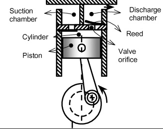
Single acting
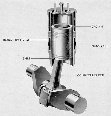
They are the reciprocating compressor which has piston working only in one direction. The other end of the piston is often free or open from which no work is performed. There is only one side compression or the upper part of the piston is used to compress the air. The bottom part is open to crankcase and is not utilized for the compression of air.
Double acting
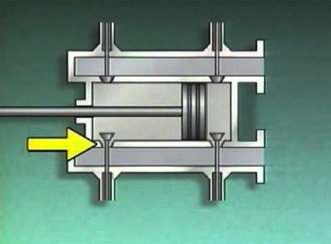
As from its name it uses its both sides to compress the air. These type of compressors have two sets of suction/intake and delivery/exhaust valve on both sides of the piston. As the piston moves up and down, both sides of the piston is utilized in compressing the air .The intake and exhaust valve operates corresponding to the movement of the piston or with the stroke of the compressor. The air is compressed accordingly and delivered continuously as compared to single-acting air compressor.
Here both of sides are effectively used for compressing the air.
Diaphragm
Its name clarifies the design of the compressor. The cylinders of various stages are found in a straight line when seen from the top that’s why they are called in line compressors. These are most commonly used compressors in the area where there is a need of varying pressure. They have simple design and commonly driven by electric motors or diesel engines.
V-shaped compressors
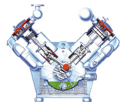
They are come under air cooled compressors with concentric valves mounted on each cylinder head unit which are placed in V-shaped i.e. at the angle of 90 degrees from each other and may or may not be connected to same crank pin on the crank shaft.
They are compressors of higher capacity so the cooling is required. The v-shaped is given to such compressor for achieving better torque and balancing by displacing different units at some angle.
Question 15) Define the design aspects of pelton wheel turbine?
Answer 15) Design aspects of Pelton Turbine
Following are the aspects to be considered while designing the Pelton wheel turbine.
- Velocity of jet
- Velocity of wheel
- Angle of deflection of jet
- Mean diameter of the wheel
- Jet ratio
- Bucket dimensions
- Number of jets
- Number of buckets
1. Velocity of Jet
The velocity of the jet at inlet is given by

Where Cv = co-efficient of velocity =0.98 or 0.99.
H= Net head on turbine.
2. Velocity of Wheel
The velocity of wheel (u) is given by

Where,  = speed ratio = 0.43 to 0.48
3. Angle of Deflection of Jet :The angle of deflection of jet after striking the buckets is taken as 165o if no deflection angle is given.
4. Mean Diameter of The Wheel
The mean diameter or the pitch diameter D of the pelton turbine is given by

5. Jet Ratio
It is defined as the ratio of the pitch diameter (D) of the pelton turbine to the diameter of the jet (d). It is denoted by m and is given as
m = D/d
Jet ratio (m) is lies between 11 to 16 for maximum hydraulic efficiency. However, In most of the cases it is taken as 12.
6. Bucket Dimensions
Buckets dimensions are designed in such a way that its breadth should be 3 to 4 times of diameter of jet, length should be 2 to 3 times of diameter of jet and thickness should be 0.8 to 1.2 times the diameter of jet.
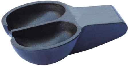
Fig 7: Pelton Wheel Bucket
7. Number of Jets
It is obtained by dividing the total rate of flow through the turbine by the rate of flow of water through a single jet.
In general, Number of jets are limited to two in case of vertical runner and six in case of horizontal runner.
8. Number of Buckets
The number of buckets (z) on a runner is given by

Where,
D = Pitch diameter
d = Diameter of Jet
m = jet ratio