A1) Pipe flow, a branch of hydraulics and fluid mechanics is a type of liquid flow within a closed conduit (conduit in the sense of a means of containment). The other type of flow within a conduit is open channel flow. These two types of flow are similar in many ways but differ in one important aspect. Pipe flow does not have a free surface which is found in open-channel flow. Pipe flow, being confined within a closed conduit, does not exert direct atmospheric pressure but does exert hydraulic pressure on the conduit.
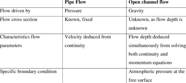
Not all flow within a closed conduit is considered pipe flow. Storm sewers are closed conduits but usually maintain a free surface and therefore are considered open-channel flow. The exception to this is when a storm sewer operates at full capacity and then can become pipe flow.The energy in pipe flow is expressed as head and is defined by the Bernoulli equation. To conceptualize head along the course of flow within a pipe, diagrams often contain a hydraulic grade line (HGL). The differences between pipe flow and open channel flow are as follows:
|
A2) Open Channels are classified as:
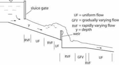
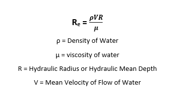
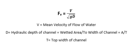
A3) The flow in the channel can be classified as:
1. Steady and Unsteady FlowIn an open channel flow, if the flow parameters such as depth of flow, the velocity of flow, and the rate of flow at a particular point on the fluid do not change concerning time, then it is called steady flow.If v is the velocity of the fluid, Q is the rate of flow and d is the depth of flow, then for a steady flow:dv/dt = 0; dQ/dt = 0; dy/dt = 0;And is at any point on the open channel flow, the flow parameters like depth of flow, the velocity of flow, and rate of flow do change their value concerning time, then it is called an unsteady flow. It is hence given by:dV/dt, dQ/dt and dy/dt not equal to Zero2. Uniform Flow and Non-Uniform FlowThe flow in the channel is said to be uniform, if, for a given length of the channel, the velocity of flow, the depth of flow remains constant. i.e.dy/dS = 0 ; dv/dS=0;In a Non-uniform flow, the flow parameters like velocity, depth of flow, etc do not remain constant for a given length of the channel.dy/dS and dv/dS not equal to zero.The Non-uniform flow can be again defined as Rapidly varying flow (R.V.F) and Gradually Varied Flow (G.V.F). In the case of R.V.F, the depth of flow rapidly changes over a smaller length of the channel. It rises suddenly for a short length and settles back. While in a G.V.F, the depth of flow changes gradually over a longer length of the channel.
|
|
|
|
|
Hence, Kinetic energy transfer through area ΔA per unit time = = Kinetic energy transfer through an area A per unit time=
Definition sketch
|
 ( ∫ V3.dA)/Vm3.∫dA (1.5)The second figure shows a typical cross-section of a natural river comprising of the main river channel and the flood plain on each side of the main channel. The flow velocity in the floodplain is usually very low as compared to that in the main section. Also, the variation of flow velocity in each subsection is small. Therefore, each subsection may be assumed to have the same flow velocity throughout. In such a case, the integration of various terms of Eq. 1.5 may be replaced by summation as follows:α= (V13A1+V23A2+V33A3)/Vm3A1+A2+A3 (1.6)in whichVm=(V1A1+V2A2+V3A3)/A1+A2+A3 (1.7) By substituting Eq. 1.7 into Eq. 1.6 and simplifying, we obtainα =(V13A1+V23A2+V33A3)(A1+A2+A3)2/ V1A1V2A2V3A33 (1.8) Note that Eq. 1.8 is written for a section that may be divided into three subsections each having uniform velocity distribution. For a general case in which total area A may be subdivided into N such subareas each having uniform velocity, an equation similar to Eq. 1.8 may be written as
|
|
 ΔA. By integrating this expression over the total area, we getMomentum transfer through area A per unit time = ρ ∫ V2 dA By introducing the momentum coefficient, β, we may write the momentum transfer through area A in terms of the mean flow velocity, Vm, for the channel section, i.e.,Momentum transfer through an area A per unit time= βρV2 ∫ dA Hence, it follows from the previous two equations that
|
A7) Static pressure is what is commonly called simply the pressure of the fluid. It’s a measure of the amount that fluid pressure exceeds local atmospheric pressure. It is measured through a flat opening that is parallel with the fluid flow
Stagnation pressure is also a measure of the amount that fluid pressure exceeds local atmospheric pressure, but it includes the effect of the fluid velocity converted to pressure. It is measured through a flat opening that is perpendicular to the direction of fluid flow and facing into the fluid flow. Dynamic pressure (also called velocity pressure) is a measure of the amount that the stagnation pressure exceeds static pressure at a point in a fluid. It can also be interpreted as the pressure created by reducing the kinetic energy to zero.Q8) Describe methods of supporting current meters and measuring velocity.
A8) Method for supporting current meter
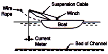
So far as possible, the current meter should be suspended similarly as it is done for ratings. When the depth of water in the channel is more, the current-meter is suspended using a fine cable or a wire rope and lowered to the required depth. Here it becomes necessary to use a boat for suspending the current-meter. The boat should be a pig. Current-meter measurement is equipped with the arrangement required for raising rivers and lowering the meter
Current meter measurement in rivers
The boat is moored to the wire rope which is stretched across the river, at the determined point in the river. When the channel carries water at shallow depths the suspension cable and the weight are removed and the current-meter is mounted on a wading rod. The rod is made to rest on the channel bed at a required position for taking measurements. In this method as the water is shallow boat is not required. The current-meter may be fixed at any depth on the wading rod for observing velocity.Methods of Measuring Velocity:When the velocity is measured by the current-meter at 0.5 D then to get the mean velocity of the section the observed velocity should be multiplied with a coefficient of 0.96. Alternatively, to obtain the mean velocity of flow at a particular section, velocities may be observed at 0.2 and 0.8 of depth from the water surface. The mean of these two readings gives the mean velocity of flow at that section. Generally, mean velocity of flow at a section is obtained by keeping the meter at 0.6 B. In the observed velocity, corrections are made for any obliquity of the current with the cross-section line and also for drift. It is necessary to conduct a vertical velocity distribution experiment at each site to decide the point of average velocity.Q9) The discharge in a channel with a bottom width of 3 m is 12 m3/s. If Manning’s 𝑛 is 0.013 m–1/3 s and the streamwise slope is 1 in 200, find the normal depth if: (a) the channel has vertical sides (i.e. rectangular channel); (b) the channel is trapezoidal with side slopes of 2H:1V.
A9)
𝑏 = 3 m (base width) 𝑄 = 12 m3 /s 𝑛 = 0.013 m−1⁄3 s 𝑆 = 0.005 (a) Discharge: 𝑄 = 𝑉𝐴 where, in normal flow,
Hence,
Rearranging as an iterative formula for ℎ:
Here, with lengths in metres, ℎ = 0.8316 (1 + 2ℎ/3)2/5 Iteration (from, e.g., ℎ = 0.8316) gives ℎ𝑛 = 1.024 m Answer: normal depth = 1.02 m. (b) Geometry: trapezoidal cross-section with base width b, surface width 𝑏 + 2 × (2ℎ) and two sloping side lengths √ℎ2 + (2ℎ)2 = ℎ√5. Area and wetted perimeter:
Hydraulic radius:
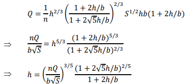
Discharge: 𝑄 = 𝑉𝐴 = 1/𝑛 𝑅ℎ2/3 S1/2 A Hence,
Here, with lengths in metres,
Iteration (from, e.g., ℎ = 0.8316) gives ℎ𝑛 = 0.7487 m Answer: normal depth = 0.749 m.
|
Q10) A rectangular concrete drive channel was constructed to conduct water to a small hydro-electric power plant. Concrete of both bed and walls of the channel has been done in a current way. The width of the channel bed is b = 2.0 m, the longitudinal slope of channel bed i0 = 0.6 ‰. What discharge will flow to the hydro-power plant, supposing that flow in the channel is uniform? The depth of water in the channel should be y0 = 1.20 m.
A10)
Rectangular area S = b.y = 2.0 x1.2 = 2.4 m2 . Wetted perimeter O = b + 2.y = 2.0 + 2 x1.2 = 4.4 m. Hydraulic radius R = S / O = 0.545 m. Slope 0.6% – for calculation, it has to be expressed as a dimensionless number, i.e. i0 = 0.0006. Velocity will be calculated from Chezy equation v = C⋅ √Ri and consequently, the discharge will be calculated from continuity equation Q = C⋅S⋅√Ri Velocity coefficient C can be calculated e.g. from the Manning formula. Value of roughness coefficient n– usual value for concrete channels should be n = 0.014.
Q = C⋅S⋅√Ri = 64.5 x 2.4x 0.545 x 0.0006 = 2.80 m3/s
|
