Back to Study material
FM 2

UNIT-6PUMPS AND TURBINES Q1) Classify hydraulic turbines with examples. A1) Hydraulic turbines are classified based on the following important factors: 1. Based on the action of water on blades or the energy available at the turbine inlet, hydraulic turbines are classified as impulse and reaction turbines. Impulse turbine: In this type of turbine the energy of the fluid entering the rotor is in the form of the kinetic energy of jets. Example: Pelton turbine. Reaction turbine: In this turbine, the energy of the fluid entering the rotor is in the form of the kinetic energy of jets and pressure energy of the turbine. Example: Francis turbine and Kaplan turbine. 2. Based on the direction of fluid flow through the runner, turbines are classified as tangential flow turbines, radial flow turbines, axial flow turbines, and mixed flow turbines. Tangential flow turbine: In this type of turbine water strikes the runner along the tangential direction, these turbines are also known as peripheral flow turbines. Example: Pelton turbine. Radial flow turbine: In this type of turbine water flows through the runner along the radial direction. Example: Francis turbine. Axial flow turbine: In this type of turbine water flows through the runner along the axial direction. Example: Kaplan turbine. Mixed flow turbine: In this type of turbine water enters the runner radially and leaves the runner axially. Example: Francis turbine. 3. Based on the specific speed of the runner, turbines are classified as low-specific speed turbines, medium-specific speed turbines, and high-specific speed turbines. Low specific speed turbines: Such turbines have usually high heads in the range of 200 m to 1700 m and these machines require low discharge. These turbines have specific speeds in the range of 10 to 30 for a single jet and 30 to 50 for a double jet. Example: Pelton turbine Medium specific speed turbines: Such turbines have usually medium heads in the range of 50 m to 200 m and these machines require medium discharge. These turbines have specific speeds in the range of 60 to 400. Example: Francis turbine. High specific speed turbines: Such turbines have usually very low heads in the range of 2.5 m to 50 m and these machines require high discharge. These turbines have a specific speed in the range of 300 to 1000. Example: Kaplan turbine.Q2) Mention the general characteristics features of Pelton, Francis, and Kaplan turbines.A2) Pelton wheel turbine is an impulse turbine. These turbines have usually high heads in the range of 200 m to 1700 m and these machines require low discharge, hence the specific speed is low in the range of 10 to 30. In this type of turbine, water strikes the runner along the tangential direction, these turbines are also known as peripheral (tangential) flow turbines. Francis turbine is a reaction turbine. These turbines have usually medium heat in the range of 50 m to 200 m and these machines require medium discharge, hence the specific speed is medium in the range of 60 to 400. In this type of turbine water enters radially and leaves axially or vice versa, these turbines are also known as mixed flow turbines. Kaplan turbine is also a reaction turbine. These turbines have usually very low heads in the range of 2.5 m to 50 m and these machines require high discharge, hence the specific speed is high in the range of 300 to 1000. In this type of turbine water flow through the runner along the axial direction, these turbines are also known as axial flow turbines. Q3) With a neat sketch explain the working of a Pelton turbine. A3) Pelton wheel turbine is an impulse turbine working under the high head and low discharge. In this turbine water carried from the penstock enters the nozzle emerging out in the form of a high-velocity water jet. The potential energy of water in the penstock is converted into kinetic energy by a nozzle which is used to run the turbine runner.


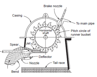
 Pelton WheelThe figure shows the main components of the Pelton wheel, water from a high head source or reservoir like a dam enters the turbine runner through large-diameter pipes known as penstocks. Each penstock pipe is branched in such a way that it can accommodate a nozzle at the end. Water flows through these nozzles as a high-speed jet striking the vanes or buckets attached to the periphery of the runner. The runner rotates and supplies mechanical work to the shaft. Water is discharged at the tailrace after doing work on the runner. In a Pelton wheel the jet of water strikes the bucket and gets deflected by the splitter into two parts, this negates the axial thrust on the shaft. Q4) Derive an expression for force, power, and efficiency of a Pelton wheel with the help of velocity triangles.A4)

) The total head available from the reservoir above the nozzle is H1

Head loss in pressure tunnel and penstock due to friction = hf

Head loss in the nozzle = hn

Net head available for power generation at the exit of nozzle = H


H=H1 - hf -hn


Where            hf = flv2/2gd


Where

l = length of penstock

v = Velocity in penstock

d = diameter of penstock

f = coeff. of friction


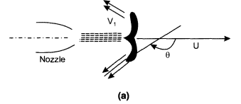
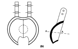
In practice, the penstock is usually sized so that at rated power the net head is usually 85-95% of the total head. The net head is taken to calculate the hydraulic efficiency of the turbine. The jet strikes the bucket at the center and takes a tum of almost 1800 and leaves on both sides of the bucket as shown in ( a), (b)


(a) Jet impingement (b) double hemispherical shape of buckets.

The velocity of the jet is given by

VI =√2gH                                                                                                         

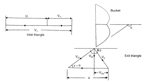
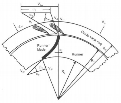
The inlet and exit velocity diagrams are shown in the next fig.

The total energy transferred to the wheel is given by Euler's Equation.


As the turbine is axial the tangential velocity is the same at the inlet and exit

ul = u2 = U            so that Euler's equation becomes


Velocity Diagram

The inlet velocity triangle is a straight line, we have

V rl = VI - u  and  VIw = VI

Also, Vr2 = k Vri, where k is coefficient ot-velocity due to friction.

The relative velocity vr2 is tangential to the exit tip of the buckets. Superimposing peripheral velocity u we obtain absolute velocity V2. The velocity Vr2 makes an angle θ with the central line of the bucket.

Vr2 = k Vri = k(VI - u) thus

V2w = u - Vr2 cos (π-θ)

Vr2 = U + Vr2 cos θ

V2w = U + k (VI - U ) cos θ

Writing Euler's equation


Substituting,  V2w = u + k(VI - u) cos θ ; as VIw = V1. we have


The equation shows that there is no energy transfer when the bucket velocity u is either zero or equal to jet velocity VI. It is reasonable to expect therefore the maximum energy transfer will occur at some intermediate velocity of the bucket velocity. Thus differentiating E for u and equating to zero for maximum energy transfer

Hence,     cannot be zero

We have u/V1=1/2

Thus tangential velocity is half the jet velocity for maximum energy transfer. Substituting this value in eq

Inlet kinetic energy to the jet= V12/2g

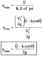
Thus maximum theoretical hydraulic efficiency of Pelton wheel,


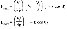
In an ideal case when θ = 180°, k = I; nmax = 100%. In practice, friction exists and the K value is in the region of 0.85 - 0.9 and also the value of θ = 165° to avoid interference between incoming and outgoing jets. Therefore u/V1 is always less than 0.5. For u/V1= 0.46 and θ = 165° , the maximum efficiency is around 90%. Rewriting the equation for Emax,

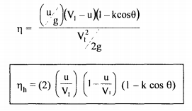
E = u/g(VI - u) (I - kcos θ) and also K.E of jet = V12/2g and hydraulic efficiency as


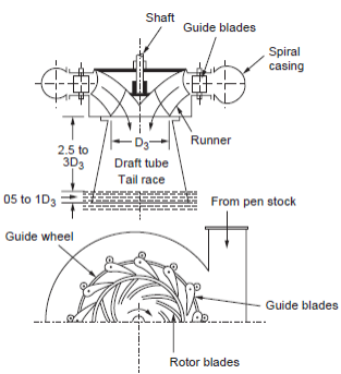
 Q5) With a neat sketch explain the working of the Francis turbine. Draw the velocity triangles of the Francis turbine. A5) Francis turbine is a reaction-type turbine. Earlier Francis turbines were purely radial flow types but modern Francis turbines are mixed flow types in which water enters the runner radially and leaves axially at the center. The figure shows the main components of Francis turbines. (i) Scroll (spiral) casing: It is also known as spiral casing. The water from penstock enters the scroll casing which surrounds the runner. The main function of the spiral casing is to provide a uniform distribution of water around the runner and hence to provide constant velocity. To provide constant velocity, the cross-sectional area of the casing gradually decreases as the water reaches the runner.


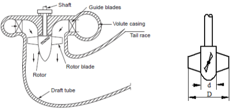
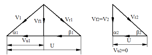
 Francis turbine(ii) Guide vanes (blades): After the scroll ring water passes over to the series of guide vanes or fixed vanes, which surrounds the turbine runner. Guide vanes regulate the quantity of water entering the runner and direct the water onto the runner. (iii) Runner (Rotor): The runner of a turbine consists of series of curved blades evenly arranged around the circumference. The vanes or blades are so shaped that water enters the runner radially at the outer periphery and leaves it axially at its center. The change in direction of flow from radial to axial when it passes over the runner causes the appreciable change in circumferential force which is responsible to develop power. (iv) Draft tube: The water from the runner flows to the tailrace through the draft tube. A draft tube is a pipe or passage of gradually increasing area which connects the exit of the runner to the tailrace. The exit end of the draft tube is always submerged below the level of water in the tailrace and must be airtight. Velocity triangles for Francis turbine: In the slow, medium, and fast runners of a Francis turbine the inlet blade angle (β1) is less than, equal to, and greater than 90° respectively. The whirl component of velocity at the outlet is zero (i.e., Vu2=0).


 Velocity diagram for Francis turbine Q6) Explain the functioning of a Kaplan turbine with the help of a sectional arrangement diagram. Draw the velocity triangles of the Kaplan turbine. A6) The Kaplan turbine is an axial flow reaction turbine in which the flow is parallel to the axis of the shaft as shown in the figure. In which water enters from penstock into the spiral casing. The guide vanes direct water towards the runner vanes without shock or formation of eddies. Between the guide vanes and the runner, the fluid gets deflected by 90° so that flow is parallel to the axis of rotation of the runner which is known as axial flow. The guide vanes impart whirl component to flow and runner vanes nullify this effect making flow purely axial. As compared to Francis turbine runner blades (16 to 24 numbers) Kaplan turbine uses only 3 to 8 blades. Due to this, the contact surface with water is less which reduces frictional resistance and losses.


 Kaplan turbineVelocity triangles for Kaplan turbine: At the outlet, the discharge is always axial with no whirl velocity component (i.e., Vu2=0). The inlet and outlet velocity triangles for the Kaplan turbine are as shown in the figure.

 Velocity triangles for Kaplan turbine Q7) What are the factors to be considered while selecting a turbine?

A7) The following points should be considered while selecting the right type of hydraulic turbines for a hydroelectric power plant.
1) Specific speed:
High specific aped is essential where the head is low and output is large because otherwise, the rotational speed will be low which means the cost of turbo-generator and powerhouse will be high. On the other hand, there is practically no need of choosing a high value of specific speed for high installations, because even with lo specific speed high rotational speed can be attained with medium capacity plants.

2) Rotational speed:
Rotational speed depends upon a specific speed. Also the rotational speed of an electrical generator with which the turbine is to be directly coupled depends on the frequency and number of pairs of poles. The value of the specific speed adopted should be such that it will give the synchronous speed of the generator.

3) Efficiency:
The efficiency selected should be such that it gives the highest overall efficiency of various conditions.

4) Part load operation:
In general, the efficiency at part loads and overloads is less than that with rated (design) parameters. For the sake of the economy, the turbine should always run with maximum possible efficiency to get more revenue.

When the turbine has to run at part or overload conditions Deriaz turbine is employed. Similarly, for low heads, the Kaplan turbine will be useful for such purposes in place of the propeller turbine.

5) Cavitations:
The installation of water turbines of reaction type over the tailrace is affected by cavitations. The critical values of cavitation indices must be obtained to see that the turbine works in a safe zone. Such values of cavitation indices also affect the design of the turbine, especially of Kaplan, propeller, and bulb types.

6) Deposition of turbine shaft:
Experience has shown that the vertical shaft arrangement is better for large-sized reaction turbines, therefore, it is almost universally adopted, whereas, in the case of large size impulse turbines, horizontal shaft arrangement is preferable.

7) Available head and its fluctuation:
a) Very high (350m and above): for heads greater than 350m, Pelton Turbine is generally employed and practically there is no choice except in very special cases.

b) High heads (150 m to 350 m): in this range either Pelton or Francis turbine may employ. For higher specific needs Francis turbine is more compact and economical than the Pelton turbine that for the same working conditions would have to be much bigger and rather cumbersome.

c) Medium heads (60 m to 150 m): a Francis turbine is usually employed in this range. Whether a high or low specific speed would be used depends on the selection of the speed.


d) Low heads (below 60m): between 30m to 60m both Kaplan and Francis turbines may be used. Francis is more expensive but yields higher efficiency at part loads and overloads. It is therefore preferable for variable loads. Kaplan turbine is generally employed less than 30m. Propeller turbines are, however, commonly used for heads up to 15m. They are adopted only when there is practically no load variation. 8) Water quality: (i.e. sand content chemical or other impurities)
Quality of water is more crucial for the reactive turbine than in reaction turbines. Reactive turbines may undergo rapid wear in high-head reactive turbines. 

Q8) Write a short note on draft tubes in reaction hydraulic turbines. Explain the functions of a draft tube in a reaction hydraulic turbine.

A8) Water, after passing through the runner is discharged through a gradually expanding tube called a draft tube. The free end of the draft tube is submerged deep into the water. Thus the entire water passage from the headrace to the tailrace is completely closed and hence doesnt come in contact with atmospheric air. It is a welded steel plate pipe or a concrete tunnel with a gradually increasing cross-sectional area at the outlet.

The functions of a draft tube are as follows,1. A reaction turbine is required to be installed above the tailrace level for easy of maintenance work, hence some head is lost. The draft tube recovers this head by reducing the pressure head at the outlet to below the atmospheric level. It increases the working head of the turbine by an amount equal to the height of the runner outlet above the tailrace. This creates a negative head or suction head. 2. Exit kinetic energy of water is a necessary loss in the case of the turbine. A draft tube recovers part of this exit kinetic energy. 3. The turbine can be installed at the tailrace level, above the tailrace level, or below the tailrace level.  Q9) What do you mean by NPSH? Is it desirable to have a lower or higher value of NPSH? A9) It is the head required at the pump inlet to keep the local pressure everywhere inside the pump above the vapour pressure. Net positive suction head (NPSH) is defined as the difference between the pumps suction stagnation pressure head and vapour pressure head.

 Where Vs is the velocity of the water in suction side, Ps and Pv are the static pressure at the suction and the vapour pressure respectively. In the suction the fluid is at atmospheric temperature so the vapour pressure remains constant, to increase the static head one has to increase net positive suction head. Therefore, NPSH should be a higher value. To have a cavitation-free operation of centrifugal pump, available NPSH should be greater than the minimum NPSH.

  Q10) What is cavitation in a centrifugal pump? What are the causes of cavitation? Explain the steps to be taken to avoid cavitation.A10) If the pressure at any point in a suction side of the centrifugal pump falls below the vapour pressure, then the water starts boiling forming saturated vapour bubbles. Thus, formed bubbles move at very high velocity to the more pressure side of the impeller blade and strike the surface of the blade and collapse there. In this way, as the pressure further decreases, more bubbles will be formed and collapses on the surface of the blades, physically enables to erosion and pitting, forming cavities on blades. This process takes place many thousand times in a second and damages the blade of a centrifugal pump. This phenomenon is known as cavitation. Causes of cavitation: The causes of cavitation are as follows, 1. The metallic surfaces are damaged and cavities are formed on the impeller surface. 2. Considerable noise and vibration are produced due to the sudden collapse of the vapour bubble. 3. The efficiency of the machine reduces. Steps to avoid cavitation: The following steps should be taken to avoid cavitation, 1. The suction losses should be minimized through the use of large diameter suction tubes with fewer bends than in the delivery pipe. 2. The pressure of the fluid flow in any part of the system should not fall below the vapour pressure. 3. The impeller should be made of better cavitation-resistant materials such as aluminium, bronze, and stainless steel.