
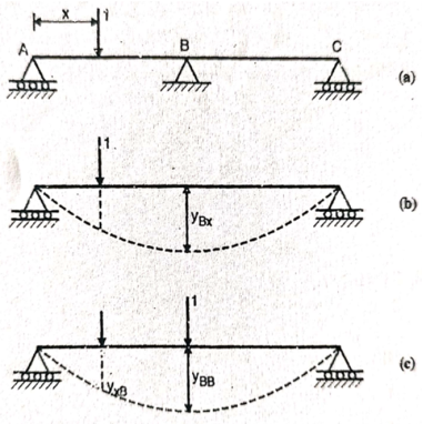
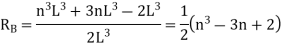
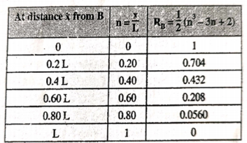
 This expression gives the reaction at BTo plot ILD for RB, take yBB = 1
|
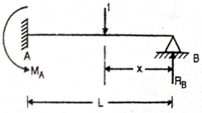
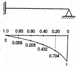
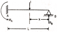
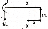
 Q2) Draw the influence line diagram using Muller Breslau’s principle for the propped cantilever of span L shown in figure fixed at A and simply supported at B for reaction at B.
|
|
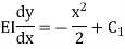
Integrating above equation,
Integrating it again we get,
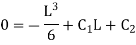
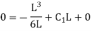
Applying boundary condition, at support A, both slope and deflection is zero. Hence, at Substituting above value,
And at Substituting above values,
Therefore,
|


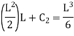


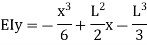
Substituting values of C1 and C2
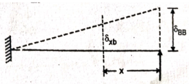
This is the general expression of deflection Deflection at B: At B, |


Substituting above value in expression of deflection,
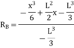
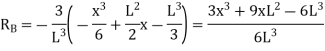
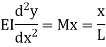
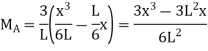
We know that, reaction at B,
Put
|


|
|
|
|
 Integrating this equation w.r.t. x
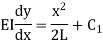 Integrating it again we get,
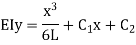
|
Hence, at B At B Substituting above value,
Substituting values of C1 and C2
This is the general expression of deflection And,
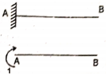
At A,
Slope at A
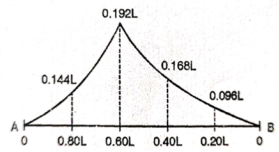
ILD for moment at A
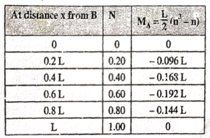
Put
Prepare a table of the values of MA for n ranging from 0 to 1, as under |


|
|
|
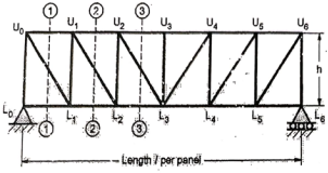
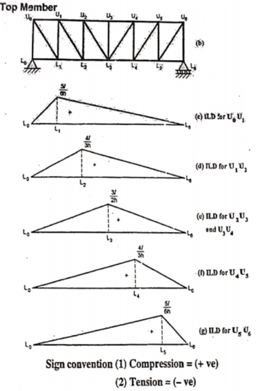
b. When unit load is at L1, R2 = 1/6
c. When unit load is in portion L1 to L6, taking moment about L1 we get,
When unit load is at L1, R1 = 5/6
When unit load is at L6, R1 = 0
|


|
|

|
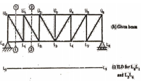
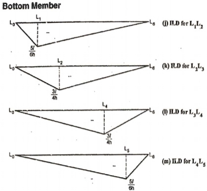
By observation Similarly, ii. ILD for L1 L2 : When unit load is on left part of section, consider right part of section in equilibrium section from figure (h)
When unit load is at L0, R2 = 0
When unit load is at L1, R2 = 5/6
When unit load is on right part,
When unit load is at L1, R2 = 5/6
When unit load is at L6, R1 = 0
|


|
|
|

|
|
|

|
|
|
|

|
|


