SM
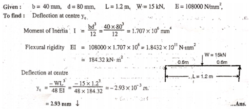
Unit - 5Slope and Deflection of Determinate BeamsQ1) A cast iron beam 40 mm wide and 80 mm deep is simply supported on a spam of 1.2 m. The beam carries a point load of 15 kN at the center. Find the deflection at the center. Take E=10800 N/mm2. A1)
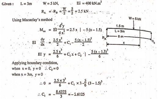
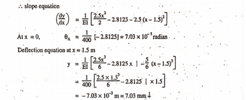
Q2) A simply supported beam of length 3 m is loaded centrally by a point load of 5 kN. Find the location and values of maximum deflection and slope (in radian) of the beam. Take flexural rigidity of the beam section as 400 kN-m2.A2)
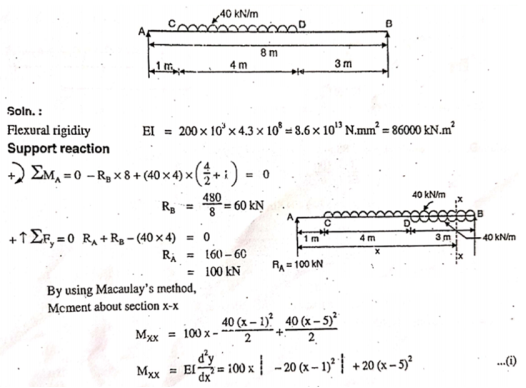
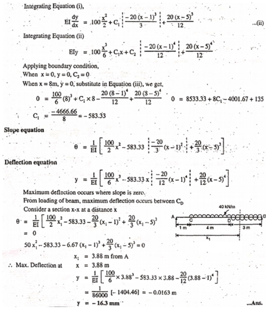
Q3) Following figure shows a simply supported beam of uniform section whose moment of inertia is 4.3 x 108 mm4. For loading shown, find the position and magnitude of maximum deflection. Take E = 200 kN/mm2.A3)
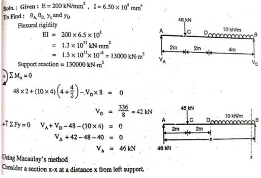
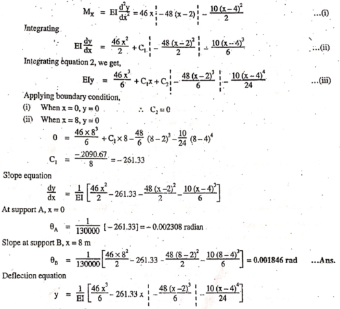
Q4) For simply supported beam shown in figure. Find 1. Slope at end and 2. Deflection at C and D. Take E = 200 kN/mm2 and I = 6.5 x 108 mm4.
A4)
Q5) Explain two theorems for Area-Moment Method.A5) Theorem 1 for Area Moment Method:The change in slope between the tangents drawn to the elastic curve at any two points A and B is equal to the product of  multiplied by the area of the moment diagram between these two points.
Theorem 2 for Area Moment Method:The deviation of any point B relative to the tangent drawn to the elastic curve at any other point A, in a direction perpendicular to the original position of the beam, is equal to the product of  multiplied by the moment of an area about B of that part of the moment diagram between points A and B.
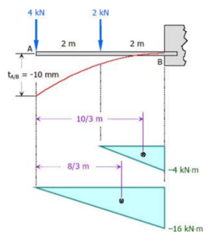
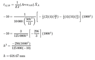
Q6) The cantilever beam shown in Figure below has a rectangular cross-section of 50 mm wide and is h mm high. Find the height h if the maximum deflection is not to exceed 10 mm. Use E = 10 GPa.
A6)
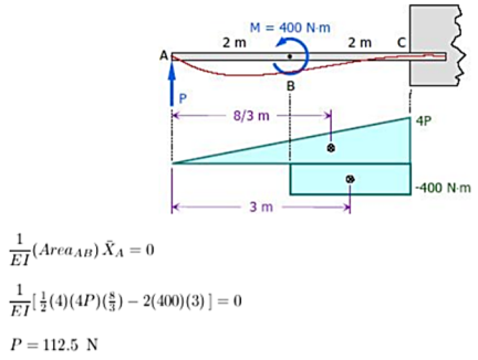
Q7) For the cantilever beam shown in Figure below, what is the force (P) at point A that will cause zero deflection at A?
A7)
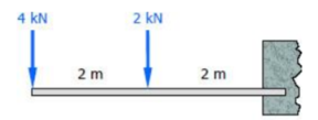
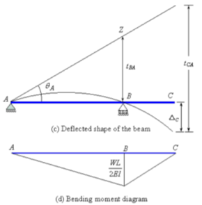
Q8) Determine the deflection at the free end of the beam shown in Figure below, using Area Moment method.
A8)
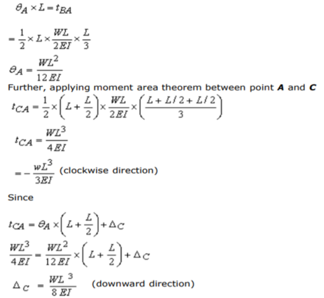
Applying second moment area theorem between points A and B will give the slope at A.
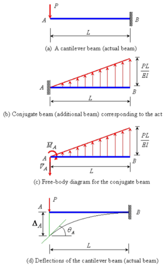
Q9) Determine the slope and deflection of point A of the of a cantilever beam AB of length L and uniform flexural rigidity EI. A concentrated force P is applied at the free end of beam.
A9) The conjugate beam of the actual beam is shown in Figure 4.8(b). A linearly varying distributed upward elastic load with intensity equal to zero at A and equal to PL/EI at B. The free-body diagram for the conjugate beam is shown in Figure 4.8(c). The reactions at A of the conjugate beam are given by
The slope at A,  and the deflection
  at the free end A of the actual beam in Figure (d) are respectively equal to the shearing force
  and the bending moment
  at the fixed end A of the conjugate beam in Figure (d)Hence,
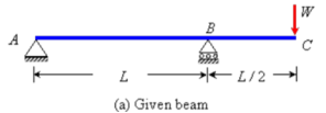
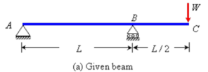
Q10) Determine the deflection at the free end of the beam shown in Figure below, using conjugate beam method.
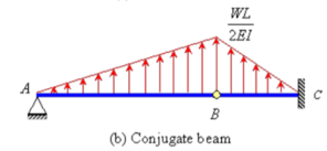
A10) The corresponding conjugate beam and loading are shown in Figure (b).
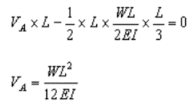
The loading is upward linearly distributed load with maximum value of  at B. Taking moment about point B, the vertical reaction at A in the conjugate beam is given by
The bending moment at C (by taking moment about C) is given by
Hence, the deflection of point C will be equal to  in the downward direction.
|
| |
| |
|
|
|
|
|
|
 multiplied by the area of the moment diagram between these two points.
|
 multiplied by the moment of an area about B of that part of the moment diagram between points A and B.
And
|
|
|
|
|
|
|
|
|
|
|
 and the deflection
  at the free end A of the actual beam in Figure (d) are respectively equal to the shearing force
  and the bending moment
  at the fixed end A of the conjugate beam in Figure (d)Hence,
|
|
|
 at B. Taking moment about point B, the vertical reaction at A in the conjugate beam is given by
|
|
 in the downward direction.
0 matching results found
