Unit 2
Principles of Pipelining and Vector Processing
Q1) What do you understand by Vector Processing Concepts? And also classify Vector instructions?
A1)
There is a category of machine issues that are beyond the capabilities of a conventional computer These issues need large range of computations on multiple data things, which will take a traditional computer (with scalar processor) days or maybe weeks to finish.
Such complicated instructions that operates on multiple data at constant time needs a much better approach of instruction execution that was achieved by Vector processors.
Scalar CPUs will manipulate one or 2 data things at time, that isn't terribly economical. Also, straightforward instructions like ADD A to B, and store into C don't seem to be much economical.
Addresses are used to point to the memory location wherever the information to be operated are going to be found, that ends up in value-added overhead of data search. Therefore till the information is found, the mainframe would be sitting ideal, that may be a huge performance issue.
Hence, the conception of Instruction Pipeline comes into image, during which the instruction passes through many sub-units successively. These sub-units perform varied freelance functions, for example: the primary one decodes the instruction, the second sub-unit fetches the information and also the third sub-unit performs the mathematics itself. Therefore, whereas the information is fetched for one instruction, mainframe doesn't sit idle, it rather works on decryption future instruction set, ending up operating like a mechanical system.
Vector processor, not solely use Instruction pipeline, however it additionally pipelines the information, functioning on multiple data at constant time.
A normal scalar processor instruction would be ADD A, B, that ends up in addition of 2 operands, however what if we will instruct the processor to add a {group a gaggle a bunch} of numbers(from zero to n memory location) to another group of numbers(let’s say, n to k memory location). This can be achieved by vector processors.
In vector processor one instruction, will provoke multiple data operations that saves time, as instruction is decoded once, and so it keeps on operational on completely different data things.
Vector instructions can be classified as below:
• Vector-Vector Instructions: In this type, vector operands are fetched from the vector register and stored in another vector register. These instructions are denoted with the following function mappings:
F1: V -> V
F2: V × V -> V
For example, vector square root is of F1 type and addition of two vectors is of F2.
• Vector-Scalar Instructions: In this type, when the combination of scalar and vector are fetched and stored in vector register. These instructions are denoted with the following function mappings:
F3: S × V -> V where S is the scalar item
For example, vector-scalar addition or divisions are of F3 type.
• Vector reduction Instructions: When operations on vector are being reduced to scalar items as the result, then these are vector reduction instructions. These instructions are denoted with the following function mappings:
F4: V -> S
F5: V × V -> S
For example, finding the maximum, minimum and summation of all the elements of
Vector are of the type F4. The dot product of two vectors is generated by F5.
• Vector-Memory Instructions: When vector operations with memory M are performed then these are vector-memory instructions. These instructions are denoted with the following function mappings:
F6: M-> V
F7: V -> V
For example, vector load is of type F6 and vector store operation is of F7.
Q2) What do you understand by pipelining? Also discuss pipeline throughput and pipeline efficiency of non-linear pipelining?
A2)
Ans. Pipelining is a technique of decomposing a sequential process into sub operations, with each sub process being executed in a special dedicated segment that operates concurrently with the other segments.
A pipeline can be visualized as a collection of processing segments through which binary information flows. Each segment performs partial processing dedicated by the way the task is partitioned.
The result obtained from the computation in each segment is transferred to the next segment in the pipeline. The final result is obtained after the data have passed through all segments. The name "pipeline" implies a flow of information analogous to an industrial assembly line. It is the characteristic of pipeline that several computations can be in program in distinct segments at the same time. The overlapping of computation is made possible by associating a register with each segment in the pipeline. The registers provide isolation between each segment so that each can operate on distinct data simultaneously.
Pipeline Efficiency – The stage utilization is the percentage of time that each pipeline stage is used over a sufficiently long series of task initiations. The pipeline efficiency is determined by the accumulated rate of all stage utilizations. There exists a relationship between the pipeline throughput and pipeline efficiency. A shorter latency cycle results in higher throughput. Higher efficiency specifies less idle time for pipeline stages.
The two measures are related with a function of the reservation table and of the initiation cycle adopted. At the steady state in any acceptable initiation cycle at least one stage of the pipeline should be fully (100%) utilized. Otherwise, the pipeline capability has not been fully explored. In such situations, the initiation cycle may not be optimal and another initiation cycle should be examined for enhancement.
Pipeline Throughput- The initiation rate or the average number of task initiations per clock cycle is the pipeline throughput. When N tasks are initiated within n pipeline cycles, the initiation rate or pipeline throughput is measured as N/n. This rate is determined mainly by the inverse of the MAL adapted. Hence, the scheduling strategy influences the pipeline performance.
Generally, the smaller the adapted MAL, the greater the throughput that can be expected. The maximum achievable throughput is one task initiation per cycle, when the MAL is 1 because 1 < MAL < the shortest latency of any greedy cycle. The pipeline throughput becomes a fraction unless the MAL is reduced to 1.
Q3) DefineSystolic Array ? Also discuss Characteristic, advantages and disadvantages of Systolic?
A3)
Parallel processing approach diverges from ancient von Neumann design. One such approach is that the concept of systolic process using systolic array.
A systolic array may be a network of processors that rhythmically compute and pass data through the system. They derived their name from drawing an analogy to however blood rhythmically flows through a biological heart because the data flows from memory during a rhythmic fashion passing through several elements before it returns to memory. It is also an example of pipelining alongside parallel computing. It was introduced in Seventies and was employed by Intel to create CMU’s iWarp processor in 1990.
In a systolic array there are an outsized range of identical straightforward processors or process elements (PEs) that are organized during a well union structure like linear or 2 dimensional array. Every process component is connected with the opposite PEs and has a restricted personal storage.
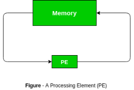
Characteristics:
Advantages of systolic array –
Disadvantages of systolic array –
Q4) What do you understand by Interleaved Memory organisation?
A4)
It is a way for compensating for the comparatively slow speed of DRAM (Dynamic RAM). During this technique, the most memory is split into memory banks which might be accessed severally with none dependency on the opposite.
For example: If we've got four memory banks(4-way Interleaved memory), with every containing 256 bytes, then, the Block destined scheme(no interleaving), can assign virtual address zero to 255 to the primary bank, 256 to 511 to the second bank. however in Interleaved memory, virtual address zero are going to be with the primary bank, one with the second memory bank, a pair of with the third bank and three with the fourth, and so four with the primary memory bank once more.
Hence, the C.P.U. will access alternate sections forthwith while not looking ahead to memory to be cached. There are multiple memory banks that move for the availability of information.
Memory interleaving could be a technique for increasing memory speed. It’s a method that creates the system a lot of economical, fast, and reliable.
For example: within the higher than example of four memory banks, information with virtual addresses zero, 1, 2, and three will be accessed at the same time as they reside in separate memory banks, thence we tend to don't have to be compelled to look ahead to the completion of information fetch, to start with, the next.
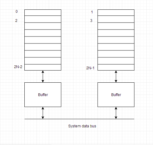
An interleaved memory with n banks is alleged to be n-way interleaved. In associate degree interleaved memory system, there are still 2 banks of DRAM however logically the system appears one bank of memory that's double as massive.
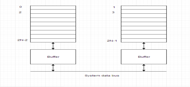
In the interleaved bank illustration below with a pair of memory banks, the primary long word of bank zero is followed by that of bank one, that is followed by the second long word of bank zero, that is followed by the second long word of bank one, and so on.
The following figure shows the organization of 2 physical banks of n long words. All even long words of the logical bank are settled in physical bank zero and every one odd long words are settled in physical bank one.
Q5) Discuss the technique of pipeline schedule optimization?
A5)
An optimisation scheme depending on the MAL is given below. the idea is to use non compute delay stage into the original pipeline. This will provide the modified reservation table, resulting in a new collision vector and an enhanced state diagram. The aim is to get an optimal latency cycle, which is absolutely the shortest.
In 1972, Shar identified the following bounds on the MAL (Minimal Average Latency) obtained by any control strategy on a statically reconfigured pipeline executing a given reservation table-
(i) The MAL is less than or equal to the average latency of any greedy cycle in the state diagram.
(ii) The MAL is lower-bounded by the maximum number of checkmarks in any row of the reservation table.
(iii) The average latency of any greedy cycle is upper-bounded by the number of l's in the initial collision vector plus 1. This is also an upper bound on the MAL. These results imply that the optimal latency cycle must be chosen from one of the lowest greedy cycles. Although, a greedy cycle is not enough to guarantee the optimality of the MAL. For example, the MAL for both function X and function Y and has met the lower bound of 3 from their respective reservation tables.
In fig. 3.6 (b), the upper bound on the MAL for function X is equal to 4 + 1 = 5, a rather loose bound. In contrast, fig. 3.6 (c) depicts a rather tight upper bound of 2 +1=3 on the MAL. Therefore, all greedy cycles for function Y provide the optimal latency value of 3, which cannot be further reduced. One require to discover the lower bound by modifying the reservation table to optimize the MAL. The method is to decrease the maximum number of checkmarks in any row. The modified reservation table must preserve the original function being evaluated. Patel and Davidson have recommended the use of noncompute delay stages to enhance pipeline performance with a shorter MAL.
Q6) Write short note on the following-
(i) Unifunctional and Multifunctional Pipeline-
(ii) Static and Dynamic Pipeline-
(iii) Scalar and Vector Pipeline-
(iv) Arithmetic pipeline
A6)
Unifunctional and Multifunctional Pipeline- Static arithmetic pipelines are design to perform a fixed function and are thus called uni functional pipeline. When a pipeline can perform more than one function it is called multi functional. A multifunctional pipeline can be either static or dynamic.
Static and Dynamic Pipeline- static pipelines perform one function at a time but different functions can be performed at different times in static pipeline, it is easy to per partition a given function into a sequence of linearly ordered some functions. A dynamic pipeline allow several functions to be performed simultaneously through a pipe line, as long as there are no conflicts in the shared usage of pipeline stages. Function partitioning in a dynamic pipeline become quite involved because the pipeline stages are interconnected with loops in addition to streamline connections.
Scalar and Vector Pipeline- Scalar and vector arithmetic pipelines differ mainly in the area of register files and control mechanism involved. Vector hardware pipelines are often built as add-on options to a scalar processor or as an attached processor drive in by a control processor. Both scalar and vector processors are used in modern supercomputer
Arithmetic pipeline- An arithmetic pipeline usually breaks a mathematical process into multiple arithmetic steps. So within the arithmetic pipeline, the mathematical process like multiplication, addition, etc. is divided into a series of steps that may be dead one by one piecemeal within the Arithmetic Logic Unit (ALU).
Example of Arithmetic pipeline
Listed below are samples of arithmetic pipeline processor:
8 stage pipeline utilized in TI-ASC
4 stage pipeline utilized in Star-100
Q7) List the various pipeline design parameter for superscalar and super pipeline processor?
A7)
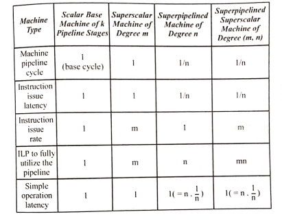
Table 1.1 Lists some parameter used in designing the scalar base machine and superscalar machines for four types of pipeline processor. Iit is assumed that all print pipelines have k stages. The machine pipeline cycle for the scalar base machine is assumed to be one time unit, known as the base cycle the maximum number of instructions that can be simultaneously executed in the pipeline is the instruction- level parallelism(ILP). All of these parameters have a value of 1 for the base machine all machines type are designed relative to the base machine. The I LP is required to fully used a given pipeline machine.
Table Pipeline Processors Design Parameter
Q8) Draw superscalar pipeline design?
A8)
The instruction decoding and execution resources are increased to form essentially m pipelines operating concurrently in an m-issue superscalar processor. The functional units may be shared by multiple pipelines at some pipeline stages. A design example in fig. 1.0 shows this resource-shared multiple pipeline structure. In this design, if there is no resource conflict and no data dependence problem then the processor can issue two instructions per cycle, in the design, there are essentially two pipelines. Both pipelines contain four processing stages namely-fetch, decode, execute and store respectively. Each pipeline contains its own unit for fetch, decode and store. The two instruction streams passing through two pipelines come out from a single source of stream. The fan-out from a single instruction stream is relate to data dependence relationship and resource constraints among the successive instructions.
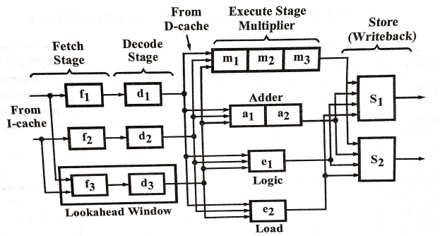
Fig. A Dual-pipeline, Superscalar Processor
It is assumed for simplicity that each pipeline stage needs one cycle, except the execute stage that need a variable number of cycles. Execute stage uses four different functional units, adder, multiplier, load unit and logic unit. The adder has two pipeline stages, the multiplier has three pipeline stages and the others each contain only one stage. S, and S, are the two store units that can be dynamically utilized by the two pipelines, based on availability at a particular cycle. A look ahead window exists with its own fetch and decoding logic. In case out-of-order instruction issue is required to obtain better pipeline throughput, this window is used for instruction look ahead.
Q9) What is Linear Pipelining?
A9)
The pipeline design technique decomposes a successive method into many sub-processes, referred to as stages or segments. A stage that performs a selected perform associated produces an intermediate result. It consists of an associate input latch, additionally referred to as a register or buffer, followed by a processing circuit. (A processing circuit is a combinable or successive circuit.) The processing circuit of a given stage is connected to the input latch of the future stage .A clock signal is connected to every input latch. At every clock pulse, each stage transfers its intermediate result to the input latch of the future stage. During this manner, the ultimate result's made once the computer file has capable the whole pipeline, finishing one stage per clock pulse. The amount of the clock pulse ought to be massive enough to supply adequate time for a sign to traverse through the slowest stage, which is termed the bottleneck (i.e., the stage needing the longest quantity of your time to complete).additionally, there ought to be enough time for a latch to store its input signals. If the clock's amount, P, is expressed as P = tb tl, then tb ought to be larger than the utmost delay of the bottleneck stage, and tl ought to be adequate for storing data into a latch.
Q10) Discuss non-linear pipeline processors. Also discuss pipeline Conflicts?
A10)
To perform variable functions at different times, a dynamic pipeline is reconfigured. The traditional linear pipelines are static pipelines as they are used to perform fixed functions. A dynamic pipeline permits feed forward and feedback connections apart from the streamline connections. That is why. such a structure is known as a non-linear pipeline. It is simple to split a given function into a sequence of linearly ordered sub functions in a static pipeline. However, function splitting in a dynamic pipeline is involved as the pipeline stages are interconnected with loops apart from streamline connections. Fig. 1.2 shows a multifunction dynamic pipeline.
There are three stages in this pipeline. There is a feed forward connection from S, to S, and two feedback connections from S3 to S2 and from S, to S, in addition to the streamline connections from S to S2 and from S2 to S3. The scheduling of successive events into the pipeline is made a nontrivial task by these feed forwardand feedback connections. The output of the pipeline is not essentially from the last stage with these connections. In fact, one can use the same pipeline to evaluate different functions following different dataflow patterns.
 Fig.
Fig.
There are some factors that cause the pipeline to deviate from its normal performance. Some of these factors are given below:
2. Data Hazards: When several instructions are in partial execution, and if they reference the same data then the problem arises. We must ensure that the next instruction does not attempt to access data before the current instruction because this will lead to incorrect results.
3. Branching: In order to fetch and execute successive instruction, we tend to should grasp what that instruction is. If this instruction may be a conditional branch, and its result can lead US to successive instruction, then successive instruction might not be renowned till this one is processed.
4. Interrupts: Interrupts set unwanted instruction into the instruction stream. Interrupts have an effect on the execution of the instruction.
5. Data Dependency: It arises once an instruction depends upon the results of a previous instruction however this result's not nevertheless on the market.