Unit -3
Advanced SQL
Q1) Explain PL/SQL with its features?
A1)
PL SQL
PL/SQL (Procedural Language/SQL) is extension to SQL. PL/SQL consist two versions first is a component of the Oracle server, and second is a separate engine embedded during a number of Oracle tools. They very almost like one another and have an equivalent programming constructs, syntax, and logic mechanisms, although PL/SQL for Oracle tools has some extensions to suit the wants of the actual tool.
PL/SQL has concepts almost like modern programming languages, like variable and constant declarations, control structures, exception handling, and modularization. PL/SQL is a block-structured language and blocks are separate or nested within each other.
The PL/SQL programming language was developed by Oracle Corporation as procedural extension language for SQL and therefore the Oracle relational database. Following are some facts about PL/SQL
• PL/SQL is a portable, high-performance transaction-processing language.
• PL/SQL provides a built-in, interpreted and OS independent programming environment.
• PL/SQL also can directly be called from the command-line SQL*Plus interface.
• Direct call is made up of external programing language calls to database.
• PL/SQL's general syntax is designed depends on ADA and Pascal programming language.
• Aside from Oracle, PL/SQL is out there in TimesTen in-memory database and IBM DB2.
Features of PL/SQL
PL/SQL has the subsequent features
Advantages of PL/SQL
PL/SQL has the following advantages
Q2) Explain general structure of PL/SQL block?
A2)
The basic units contains a PL/SQL program are procedures, functions, and anonymous blocks. A PL/SQL block has up to 3 parts:
• An optional declaration part, during which variables, constants, cursors, and exceptions are defined and possibly initialized;
• A compulsory executable part, during which the variables are manipulated;
• Exception part which is optional used to handle any exceptions raised during execution.
Declarations
Variables and constant variables can be declared before they are referenced in other statements, including other declarative statements. Examples of declarations are:
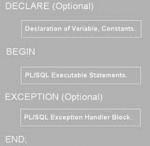
Figure 3.1.1(I)General structureof a PL/SQLblock.
vStaffNo VARCHAR2(5);
vRent NUMBER(6, 2) NOT NULL :5 600;
MAX_PROPERTIES CONSTANT NUMBER: 5 100;
It is possible to declare a variable as NOT NULL and initial value must be assigned to the variable. it's also possible to declare a variable to be of an equivalent type as a column during a specified table or another variable using the type attribute. for instance , to declare that the vStaffNo variable is that the same type because the staffNo column of the Staff table, we write as:
vStaffNo Staff.staffNo %TYPE;
vStaffNo1 vStaffNo%TYPE;
Same as we will declare a variable to be of an equivalent type as a whole row of a table or view using the %ROWTYPE attribute. during this case, the fields within the record take their names and data types from the columns within the table or view. for instance , to declare a vStaffRec variable to be a row from the Staff table, we could write:
vStaffRec Staff %ROWTYPE;
%TYPE and %ROWTYPE aren't standard SQL.
Assignments
In the executable a part of a PL/SQL block, variables are often assigned in two ways: using the traditional assignment statement (:5) or because the results of an SQL SELECT or FETCH statement. For example:
vStaffNo :5 ‘SG14’;
vRent :5 500;
SELECT COUNT(*) INTO x FROM PropertyForRent WHERE staffNo 5 vStaffNo;
In the third case, the variable x is about to the results of the SELECT statement. within the SQL standard, an assignment uses the SET keyword at the beginning of the line with the “5” symbol, rather than the “:5”. For example:
SET vStaffNo 5 ‘SG14’
Q3) What is stored procedure? How to create strored procedure? Illustrate with example?
A3)
Stored Procedures
A stored procedure is a set of procedural and SQL statements. Same as database triggers, stored procedures are stored within the database. The main advantages is that they're used to encapsulate and represent business transactions.
For example, you'll create a stored procedure to show a product sale, a credit update, or the addition of a new customer. By performing that, you'll encapsulate SQL statements within one stored procedure and execute them as a single transaction. There are two advantages of stored procedures:
• Stored procedures substantially minimize network traffic and increase performance. Because the procedure is stored at the server and there's no transmission of individual SQL statements over the network. The use of stored procedures boosts system performance because all transactions are executed locally on the RDBMS, so every SQL statement doesn't need to travel over the network.
• Stored procedures help reduce code duplication by means of code isolation and code sharing, thereby minimizing the prospect of errors and therefore the cost of application development and maintenance.
To create a stored procedure, you use the following syntax:
CREATE OR REPLACE PROCEDURE procedure_name [(argument [IN/OUT] data-type, A)]
[IS/AS]
[variable_namedata type[:=initial_value] ]
BEGIN
PL/SQL or SQL statements;
...
END;
Following are the details about stored procedures and their syntax:
• Argument specifies the parameters that are passed to the stored procedure. A stored procedure could have zero or more arguments or parameters.
• IN/OUT indicates whether the parameter is for input, output, or both.
• Data-type is one among the procedural SQL data types used in the RDBMS. The data types normally match those used in the RDBMS table-creation statement.
• Variables are often declared between the keywords IS and start. You want to specify the variable name, its data type, and an initial value.
Q4) Explain packages in PL/SQL?
A4)
Packages (PL/SQL)
A package may be a collection of procedures, functions, variables, and SQL statements that are grouped together and stored as one program unit. A package has two parts: a specification and a body. A package specification defines all public constructs of the package, and then the body defines all constructs that is public and private of the package, and implements the specification. In this packages provide a type of encapsulation. Oracle performs the following steps when a procedure or package is created:
• It compiles the procedure or package.
• It stores the compiled code in memory.
• It stores the procedure or package within the database.
We can create a package as:
CREATE OR REPLACE PACKAGE Staff_PropertiesPackage ASprocedure Properties_ForStaff (vStaffNo VARCHAR2);
END Staff_PropertiesPackage ;
and we create the package body as:
CREATE OR REPLACE PACKAGE BODY Staff_PropertiesPackage
AS
. . .
END Staff_PropertiesPackage ;
To reference the items declared within a package specification, we use the dotnotation. For example, we call the Properties_ForStaff procedure as follows:
Staff_PropertiesPackage . Properties_ForStaff (‘SG14’);
Q5) What is mean by Embedded SQL and Dynamic SQL?
A5)
Embedded SQL and Dynamic SQL
Embedded SQL is used to discuss with SQL statements that are contained within an application programing language like Visual Basic .NET, C#, COBOL, or Java. The program being developed could be a typical binary executable in Windows or Linux.
Embedded SQL is used to maintaining procedural capabilities in DBMS-based applications. Therefore, mixing SQL with procedural languages needs that you simply understand some key differences between SQL and procedural languages.
Run-time mismatch: SQL is a nonprocedural, interpreted language in that every instruction is parsed after that syntax is checked, and execute one instruction at a time. All of the processing takes place at the server side. The host language is a binary-executable program. The host program is runs at the client side in its own memory space.
Processing mismatch: Conventional programming languages like COBOL, ADA, FORTRAN, PASCAL, C++, and PL/I process one data element at a time. Also you can use arrays to hold data and process the array elements one row at a time. This is true for file manipulation, where the host language manipulates data one record at a time. However latest programming environments used multiple object-oriented extensions which help the programmer to manipulate data sets in a cohesive form.
Data type mismatch: SQL provides multiple data types. To understand the differences, the Embedded SQL standard2 defines a framework to integrate SQL within many programming languages. The Embedded SQL framework defines the following:
A standard syntax verify embedded SQL coding within the host language. Host variables are variables which are present in the host language that receive data from the database and process the data within the host language. All host variables are preceded by a colon (“:”) .A communication area is used to exchange status and error information between SQL and host language.
This communications area consist of two variables SQLCODE and SQLSTATE. Also interface host languages and SQL via the use of a call level interface (CLI) during which the programmer writes to an application programming interface (API). A common CLI in Windows is supported by the Open Database Connectivity (ODBC) interface.
The process need to create and run executable program with embedded SQL statements. If you've programmed in COBOL or C++, you need the multiple steps required to get the ultimate executable program. Although the precise details vary among language and DBMS vendors, the subsequent general steps are standard:
1. The programmer writes embedded SQL code within the host language instructions. The code follows the standard syntax need for the host language and embedded SQL.
2. A preprocessor is used to transform the embedded SQL into specialized procedure calls like DBMS and language-specific. The preprocessor is provided by the DBMS vendor and is particular to the host language.
3. The program is compiled using the host language compiler. The compiler creates an object code module for the program consist of DBMS procedure calls.
4. The object code is linked to the appropriate library modules and generates the executable program. This process binds the DBMS procedure calls to the DBMS run-time libraries. The binding process creates an “access plan” module that contains instructions to run the embedded code at run time.
5. The executable is run, and then the embedded SQL statement retrieves data from the database.
You can also embed individual SQL statements or a whole PL/SQL block. Programmers embed SQL statements within a host language that it's compiled once and executed as when required. To embed SQL into a host language, follow the following syntax:
EXEC SQL
SQL statement;
END-EXEC.
This syntax will work for SELECT, INSERT, UPDATE, and DELETE statements. For example following embedded SQL code will delete employee 109, George Smith, from the employee table:
EXEC SQL
DELETE FROM EMPLOYEE WHERE EMP_NUM = 109;
END-EXEC.
Remember that the above embedded SQL statement is compiled to get an executable statement. Therefore, the statement is fixed and can't change. Whenever the program runs, it deletes an equivalent row. In short above code is good just for the first run; all subsequent runs will likely generate an error.
In embedded SQL, all host variables are preceded by a colon (“:”). The host variables want to send data from the host language to the embedded SQL, or they'll be used to receive the data from the embedded SQL. To use a host variable, you need to first declare it within the host language.
For example, if you're using COBOL, you'd define the host variables within the Working Storage section. Then you'd ask them within the embedded SQL section by preceding them with a colon (“:”). For instance, to delete an employee having employee number is represented by the host variable W_EMP_NUM, consider the following code:
EXEC SQL
DELETE FROM EMPLOYEE WHERE EMP_NUM =:W_EMP_NUM;
END-EXEC.
At run time, the host variable value will be used to execute the embedded SQL statement. In COBOL area is known as the SQLCA area and is defined in the Data Division as follows:
EXEC SQL
INCLUDE SQLCA
END-EXEC.
The SQLCA area consist of two variables for status and error reporting. Following Table shows some of the main values returned by the variables.
Variable name | value | Explanation |
SQLCODE |
| Old-style error reporting supported for backward compatibility only. It returns an integer value it may be positive or negative. |
| 0 | Successful completion of command |
| 100 | No data; the SQL statement did not return any rows or not select, update, or delete any rows. |
| -999 | Any negative value indicates that an error occurred. |
SQLSTATE |
| Added by SQL-92 standard to provide predefined error codes which is defined as a character string up to 5 characters. |
| 00000 | Successful completion of command. |
|
| Multiple values in the format XXYYY where: XX-> defines the class code. YYY-> defines the subclass code.
|
SQL Status and Error Reporting Variables
The following embedded SQL code shows the use of the SQLCODE within a COBOL program.
EXEC SQL
EXEC SQL
SELECT EMP_LNAME, EMP_LNAME INTO: W_EMP_FNAME,:W_EMP_LNAME
WHERE EMP_NUM =:W_EMP_NUM;
END-EXEC.
IF SQLCODE = 0 THEN
PERFORM DATA_ROUTINE
ELSE
PERFORM ERROR_ROUTINE
END-IF.
In this example, the SQLCODE host variable is checked to find out the query completed successfully or not. In this case, the DATA_ROUTINE is performed or the ERROR_ROUTINE is performed.
Embedded SQL needs the use of cursors to hold data from a query that returns multiple value. If COBOL is used then the cursor can be declared in the Working Storage Section or in Procedure Division. The cursor need to declared and processed. Following is the syntax for cursor declaration.
EXEC SQL
DECLARE PROD_CURSOR FOR
SELECT P_CODE, P_DESCRIPT FROM PRODUCT
WHERE P_QOH > (SELECT AVG (P_QOH) FROM PRODUCT);
END-EXEC.
Next you need to open the cursor for processing:
EXEC SQL
OPEN PROD_CURSOR;
END-EXEC.
To process the data rows in the cursor use the FETCH command to retrieve one row of data at a time and place the values in the host variables. The SQLCODE must be checked to find out the FETCH command completed successfully. In this code typically contains part of a routine in the COBOL program. Such a routine is executed with the help of PERFORM command. For example:
EXEC SQL
FETCH PROD_CURSOR INTO: W_P_CODE,:W_P_DESCRIPT;
END-EXEC.
IF SQLCODE = 0 THEN
PERFORM DATA_ROUTINE
ELSE
PERFORM ERROR_ROUTINE
END-IF.
After processing all rows close the cursor as follows:
EXEC SQL
CLOSE PROD_CURSOR;
END-EXEC.
You study examples of embedded SQL in this the programmer used predefined SQL statements as well as parameters. Therefore, the end users of the programs are limited to the actions that were specified in the application programs. That style of embedded SQL is called as static SQL that means the SQL statements will not change when the application is running. For example, the SQL statement read as follows:
SELECT P_CODE, P_DESCRIPT, P_QOH, P_PRICE
FROM PRODUCT
WHERE P_PRICE > 100;
The attributes, tables, and conditions are called in the preceding SQL statement. The end users seldom work in a static environment. They need the flexibility of defining their data access requirements on the fly. Therefore, the end user requires that SQL work as dynamic as the data access requirements.
Dynamic SQLused to describe an environment in which the SQL statement is not known in advance but the SQL statement is generated at run time. At run time in a dynamic environment, a program can generate the SQL statements that are need to respond to ad hoc queries. In such environment the programmer and the end user both are know that what kind of queries are to be generated or how those queries are to be structured. For example, a dynamic SQL equivalent of the following example could be:
SELECT: W_ATTRIBUTE_LIST
FROM: W_TABLE
WHERE: W_CONDITION;
The attribute list and the condition are not known until the end user describes them. W_TABLE, W_ATTRIBUTE_LIST, and W_CONDITION are text variables which contain the end-user input values used in the query at the time of generation. Because the program uses the end-user input to build the text variables, the end user can run the same program several times to generate changeable outputs.
For example the end user required to know what products have a price less than $100; in another case, the end user also know how many units of a given product are available for sale at any time. Dynamic SQL is flexible and such flexibility carries a price. Dynamic SQL is much slower than static SQL. Dynamic SQL also requires more computer resources.
Q6) Explain Software development life cycle with sutaible diagram?
A6)
The Systems Development Life Cycle (SDLC)
The Systems Development Life Cycle (SDLC) is a life cycle of an information system. It is more important to the system designer, the SDLC provides the big picture in which the database design and application development can be mapped out and evaluated.
Figure shows the traditional SDLC which is divided into five phases: planning, analysis, detailed systems design, implementation, and maintenance. The SDLC is an iterative process. For example, the details of the feasibility study help to refine the initial assessment.
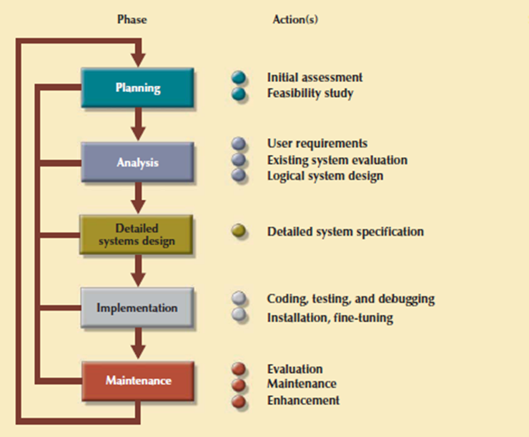
Figure 3.7.1(I) The Systems Development Life Cycle (SDLC)
1. Planning
The SDLC planning phase represent a general overview of the company and its objectives. An initial assessment of the information flow-and-extent requirements must be made during this discovery portion of the SDLC. Such an assessment should answer some important questions:
Participants in the SDLC’s initial assessment start to study and evaluate another solutions. The feasibility study represent the following:
2. Analysis
Problems defined during the planning phase are examined in details during the analysis phase. A macro analysis is combination of individual needs and organizational needs, addressing questions like:
• What are the wants of the present system’s end users?
• Do those requirements fit into the general information requirements?
The analysis phase of the SDLC is go thorough audit of user needs. The prevailing hardware and software systems are studied during the analysis phase. The results of analysis should be a far better understanding of the system’s functional areas, actual and potential problems, and opportunities. End users and therefore the system designers got to work together to identify processes and to uncover potential problem areas.
For creating a logical design, the designer use tools like data flow diagrams (DFDs), hierarchical input process output diagrams, and entity relationship (ER) diagrams. The database design’s data-modeling activities won’t to discover and describe all entities and therefore the attributes and the relationships among the entities within the database.
3. Detailed Systems Design
In this phase the designer completes the design of the system’s processes. The design consist of all the technical specifications for the screens, menus, reports, and other devices which is used to make the system a more efficient information generator. The steps are laid out for conversion from the old to the new system. Training principles and methodologies are also planned which is need to submit for management’s approval.
4. Implementation
In implementation phase, the hardware, DBMS software, and application programs are installed, and the database design is implemented. At initial stages the system enters into a cycle of coding, testing, and debugging until it is ready to be delivered. The actual database is created, and the system is customized by the creation of tables and views, user authorizations.
The database contents are added interactively or in batch mode, using multiple methods and devices:
The implementation and testing of a new system took 50% to 60% of the total development time. Therefore the advent of sophisticated application generators and debugging tools has decreased coding and testing time. After testing is completed, the final documentation is reviewed and printed and end users are trained.
5. Maintenance
When system is operational then end users begin to request changes in it. Those changes perform system maintenance activities, which is devided into three types:
Because every request for structural change needs retracing the SDLC steps, the system is always at some stage of the SDLC. Every system has a predetermined operational life span. The actual operational life span of a system based on its perceived utility. There are more reasons for reducing the operational life of certain systems. Rapid technological change is one reason for systems depends on processing speed and expandability.
Another reason is that the cost of maintaining a system. Computer-aided systems engineering (CASE) tools like System Architect or Visio Professional, helps to supply better systems within a low amount of your time and at low cost.
Q7) Explain Database Life Cycle (DBLC)?
A7)
The Database Life Cycle (DBLC)
In larger data system, the database is subject to a life cycle. The Database Life Cycle has six phases that's database initial study, database design, implementation and loading, testing and evaluation, operation as well as maintenance and evolution. Following figure shows DBLC

Figure 3.7.2(I) The Database Life Cycle (DBLC)
1. The Database Initial Study
If a designer has been called in, chances are the current system has did not perform functions deemed by the corporate. Additionally to review the current system’s operation within the company, the designer need find how and why the current system fails. That’s spending a longer to talking with end users. Database design may be a technical business and people-oriented. Database designers must be excellent communicators, and finely tuned interpersonal skills.
Based on the complexity and scope of the database environment consist of the database designer could also be one operator or a part of a systems development team composed of a project leader, one or more senior systems analysts, and one or more junior systems analysts. The word designer is employed generically here to hide a wide range of design team compositions.
The aim of the database initial study is to:
• Analyze the company situation.
• Define problems and constraints.
• Define objectives.
• Represents scope and limits.
Following figure shows the interactive and iterative processes need to complete the primary phase of the DBLC successfully.
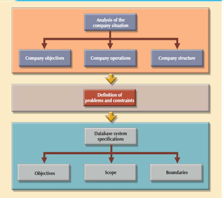
Figure 3.7.2(II) A summary of activities in the database initial study
2. Database Design
The second phase focuses on the design of the database model that support company operations and objectives. This is often the most critical DBLC phase that making sure that the final product meets user and system requirements. Within the process of database design, you would like to focus on the data characteristics required to create the database model.
There are two views of the data within the system one is that the business view of data as a source of information and other is designer’s view of the data structure, its access, and therefore the activities need to transform the data into information. Following figure shows the various views. Defining data is an integral a part of the DBLC’s second phase. To complete the design introduce the DBLC consider the following points:
• The process of database design is loosely associated with the analysis and design of a bigger system. The data component is only single element of a larger information system. The systems analysts or systems programmers are in charge of designing the other system components. Their activities create the procedures which help to transform the data within the database into useful information.
• The database design doesn't support a sequential process. Rather, it's an iterative process that gives continuous feedback designed to trace previous steps.
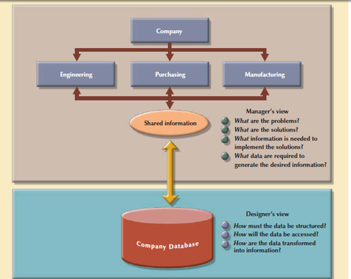
Figure 3.7.2(III) Two views of data: business manager and database designer
The database design process is shown in above Figure. It contains four stages: conceptual, logical, physical design and DBMS selection stage. The design process starts with conceptual design and moves to the logical and physical design stages.
At every stage, more details about the data model design are determined and documented. The conceptual design because the overall data as seen by the end user, the logical design because the data as seen by the DBMS, and therefore the physical design because the data as seen by the operating system’s storage management devices.
It is need to understand that the overwhelming majority of database designs and implementations are depends on the relational model. At the completion of the database design activities, you would like to complete database design able to be implemented.
3. Implementation and Loading
The output of the database design phase is a series of instructions describing the creation of tables, attributes, domains, views, indexes, security constraints, and storage and performance guidelines. In this phase you can perform all these design specifications.
Install the DBMS
This step is needed only when a new dedicated instance of the DBMS is necessary for the system. In many cases, the organization will have standardized on a particular DBMS in order to leverage investments in the technology and the skills that employees have already developed. The DBMS is installed on a new server or on existing servers.
Virtualization technique creates logical representations of computing resources that are independent of the physical computing resources. This technique is used in multiple areas of computing like the creation of virtual servers, virtual storage, and virtual private networks. The database virtualization is considered as the installation of a new instance of the DBMS on a virtual server which is running on shared hardware. This task contains system and network administrators to create appropriate user groups and services in the server configuration and network routing.
Create the Databases
In latest relational DBMSs a new database implementation needs the creation of special storage-related constructs to house the end-user tables. The constructs contains the storage group, the table spaces, and the tables. Figure shows the fact that a storage space consist of more than one table space and that a table space can contain more than one table.
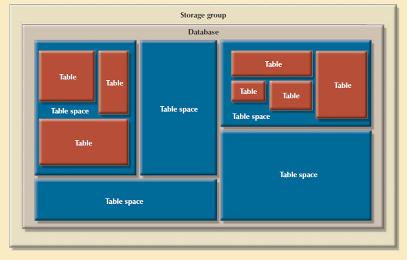
Figure 3.7.2(V) Physical organization of a DB2 database environment
For example, the implementation of the logical design in IBM’s DB2 require that you:
1. Create the database storage group. This step is compulsory for such mainframe databases as DB2. Other DBMS software may create same storage groups automatically when a database is created. Consult your DBMS documentation to see if you must create a storage group.
2. Create the database within the storage group performed by the SYSADM.
3. Assign the rights to use the database to a database administrator (DBA).
4. Create the table space in the database.
5. Create the table within the table space.
6. Assign access rights to the table spaces and to the tables within specified table spaces.
Access rights are limited to views instead of whole tables. The creation of views is not required for database access in the relational environment. For example, access rights to a table named PROFESSOR granted to the user Shannon Scott whose identification code is SSCOTT with the help of GRANT SELECT ON PROFESSOR TO USER SSCOTT;
Load or Convert the Data
After creation of database, the information must be loaded into the database tables. There’s need to migrated data from the prior version of the system. The data to be included within the system need to aggregate from multiple sources. During a best-case scenario, all of the data are going to be during a relational database in order that it are often transferred to the new database.
Data are often imported from other relational databases, Non-relational databases, flat files, legacy systems, or from manual paper-and-pencil systems. If the data format doesn't support direct importing into the new database then conversion programs are created to reformat the info in order that it are often imported. During a worst-case scenario, more data are often manually entered into the database. Once the data has been loaded, the DBA works with the application developers to test and evaluate the database.
4. Testing and Evaluation
In the design phase, decisions are taken to make sure integrity, security, performance, and recoverability of the database. During implementation and loading, these plans were put into place. In testing and evaluation, the DBA tests and fine-tunes the database to make sure that it performs for sure. This phase occurs in conjunction with applications programming. Programmers use database tools to prototype the applications during the coding of the programs. Tools like report generators, screen painters, and menu generators are useful to the applications programmers.
Q8) What is the goal of conceptual design? Explain data model verification steps in it?
A8)
Conceptual Design
The second phase of the DBLC is database design, and its four stages: conceptual design, DBMS selection, logical design, and physical design. Conceptual design is that the first stage in the database design process. The goal of this stage is to design a database that's not dependent on database software and physical details.
The output of this process may be a conceptual data model which explains the most data entities, attributes, relationships, and constraints of a given problem domain. This design is descriptive and narrative in form. It made up of a graphical representation and textual descriptions of the data elements, relationships, and constraints.
In this stage, data modeling is used to make an abstract database structure which describe real-world objects within the most realistic way possible. At this level of abstraction, the type of hardware and database model used not identified yet. Therefore, the design must be software and hardware independent therefore the system are often set up in any hardware and software platform selected.
Consider the following minimal data rule:
All that is needed is there, and all that is there is needed.
That means confirm that all data needed are in the model and that all data in the model are needed. All data elements required by the database transactions need to define in the model, and all data elements defined in the model must be used by at least one database transaction.
When you apply the minimal data rule then avoid an excessive short-term bias. Focus on the immediate data needs of the business and the future data needs.
The conceptual design contains four steps.
Data Model Verification
The data model verification step is one of the last steps in the conceptual design stage, and most critical also. In this step, the ER model verified against the proposed system processes in order to corroborate that the intended processes can be supported by the database model. Verification needs the model be run through a series of tests against:
Because real-world database design is done by teams, it is very likely the database design is divided into several components called as modules. A module is an information system component used to handles some business function like inventory, orders, and payroll. In these conditions every module is supported by an ER segment that's a subset of an enterprise ER model. Working with modules accomplishes many important ends:
• The modules are often delegated to design groups within teams, speeding up the development work.
• The modules simplify the design work. The greater number of entities within a complex design are often daunting.
• Every module contains a many manageable number of entities.
• The modules are prototyped quickly. Implementation and applications programming trouble spots are often identified more readily.
• Even if the whole system can’t be brought online quickly, the implementation of 1 or more modules will shows that progress is being made which a minimum of a part of the system is prepared to begin serving the end users.
Following are fragments of ER model:
• Might present overlapping, duplicated or conflicting views of an equivalent data.
• Might not be ready to support all system’s modules processes.
The problems solution is that the modules ER fragments are merged into one enterprise ER model. This process starts by selecting a central ER model segment and iteratively adding additional ER model segments one at a time. At every stage, for every new entity added to the model, required to validate that the new entity doesn’t overlap or conflict with a previously identified entity within the enterprise ER model.
Merging the ER model segments into an enterprise ER model triggers a careful reevaluation of the entities, followed by an in depth examination of the attributes that represents those entities. This process is used for multiple important purposes:
• The emergence of the attribute details cause a revision of the entities themselves.
• The focus on attribute details can provide clues about the nature of relationships as they're defined by the primary and foreign keys. Improperly defined relationships lead to implementation problems first and to application development problems later.
• To satisfy processing or end-user requirements, it'd be useful to make a new primary key to exchange an existing primary key.
A surrogate primary key might be introduced to replace the original primary key composed of VIDEO_ID and CUST_NUMBER.
Unless the entity details are precisely defined, it is difficult to evaluate the extent of the design’s normalization. Knowledge of the normalization levels helps guard against undesirable redundancies.
A careful review of the rough database design blueprint is probably going to lead to revisions. Those revisions will help make sure that the design is capable of meeting end-user requirements.
After finishing the merging process the enterprise ER model is verified against every modules processes. Following is the ER model verification process.
STEP ACTIVITY
- Internal: Updates/Inserts/Deletes/Queries/Reports
- External: Module interfaces
Consider that the verification process needs the continuous verification of business transactions also system and user requirements. The verification sequence must be repeated for every system’s modules. Figure shows the iterative nature of the process.
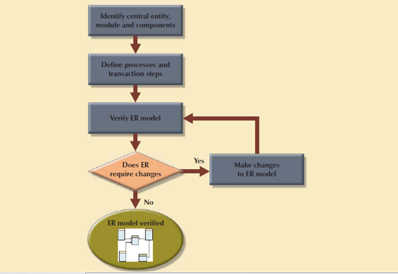
Figure 3.7.2(XI) Iterative ER model verification process
The verification process starts with selecting the central entity. The central entity is defined in terms of its participation in most of the model’s relationships, and it's the main target for many of the system’s operations. In other words, to identify the central entity, the designer selects the entity involved within the greatest number of relationships. Within the ER diagram, it's the entity with more lines connected to it than the other.
The next step is to identify the module or subsystem to which the central entity belongs and to define that module’s boundaries and scope. The entity belongs to the module that uses it most often. Once every module is identified, the central entity is placed within the module’s framework to focus your attention on the module’s details.
Within the central entity/module framework, you need to:
Processes is classified according to their:
All identified processes need to verified against the ER model. If necessary, appropriate changes are implemented. The process verification is repeated for all of the model’s modules. You’ll expect that additional entities and attributes are going to be incorporated into the conceptual model in its validation.
4. Distributed Database Design
Sometimes a database may have to be distributed between multiple geographically disperse locations. Processes that access the database may is vary from one location to a different. For example, a retail process and a warehouse storage process are to be found in several physical locations. If the database data and processes are to be distributed across the system, portions of a database, called as database fragments, present at several physical locations.
A database fragment may be a subset of a database that's stored at a given location. The database fragment could also be composed of a subset of rows or columns from one or many tables. Distributed database design defines the optimum allocation strategy for database fragments so as to make sure database integrity, security, and performance. The allocation strategy determines the way to partition the database and where to store each fragment.
Q9) Write note on DBMS Software Selection?
A9)
DBMS Software Selection
The selection of DBMS software is critical to the information system’s smooth operation. The benefits and drawbacks of the proposed DBMS software should be carefully studied. To avoid false expectations, the end user must be made aware of the restrictions of both the DBMS and therefore the database. Although the factors affecting the purchasing decision vary from company to company, some of the most common are:
Logical Design
Logical design is that the second stage within the database design process. The logical design goal is to style an enterprise-wide database based on a selected data model but independent of physical-level details. Logical design requires that each one objects within the conceptual model be mapped to the precise constructs used by the chosen database model. For example, the logical design for a relational database contains the specifications for the relations, relationships, and constraints. The logical design is worked in four steps, which are shown as following. Steps
STEP ACTIVITY
1. Mapping the Conceptual Model to the Logical Model
The first step in creating the logical design is to map the conceptual model to the chosen database constructs. Within the world, logical design present at translating the ER model into a group of relations, columns, and constraints definitions. The process of translating the conceptual model into a group of relations is shown as follows.
ITY
A strong entity is one that present at 1 side of all its relationships, that is, an entity that doesn't have any mandatory attribute that's a foreign key to a different table. Therefore, the first entities to be translated into tables would be the employee and COURSE entities. During this case, you define what would be the table name, what would be its columns and their characteristics. For instance, the relation definitions for the strong entities on SimpleCollege can be:
COURSE (CRS_CODE, CRS_TITLE, CRS_DESCRIPT, CRS_CREDIT) PRIMARY KEY: CRS_CODE
EMPLOYEE (EMP_NUM, EMP_LNAME, EMP_FNAME, EMP_INITIAL, EMP_E_MAIL)
PRIMARY KEY: EMP_NUM
Once all strong entities are mapped, you're able to map any entities involved during a supertype/subtype relationship or any weak entities. Within the case of SimpleCollege, you have the PROFESSOR entity that's a subtype of the employee entity. PROFESSOR is additionally a weak entity because it inherits its primary key from EMPLOYEE and it's existence-dependent on EMPLOYEE. At this point, you furthermore may start defining the relationships between supertype and subtype entities. For example:
PROFESSOR (EMP_NUM, PROF_SPECIALTY, PROF_RANK) PRIMARY KEY: EMP_NUM FOREIGN KEY: EMP_NUM REFERENCES PROFESSOR
Next, you start mapping all binary relationships. In the previous example you have defined the Supertype/subtype relationship between EMPLOYEE and PROFESSOR. This is an instance that shown the iterative nature of this process. Continuing with the SimpleCollege ER model define the CLASS relation and define its 1: M relationships with PROFESSOR and COURSE:
CLASS (CLASS_CODE, EMP_NUM, CLASS_TIME, CLASS_DAYS, CRS_CODE)
PRIMARY KEY: CLASS_CODE FOREIGN KEYS: EMP_NUM REFERENCES PROFESSOR
CRS_CODE REFERENCES COURSE
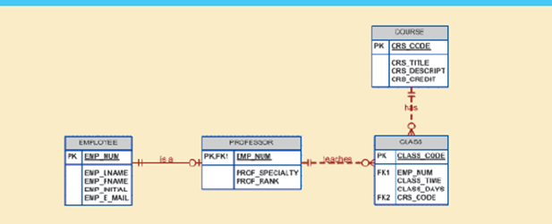
Figure 3.8(I) shows The SimpleCollege conceptual model
The logical design’s tables must correspond to the entities shown within the conceptual design, and therefore the table columns must correspond to the attributes laid out in the conceptual design. The ultimate outcome of this process may be a list of relations, attributes, and relationships which will be the basis for future step.
2. Validate the Logical Model with the help of Normalization
The logical design contain only properly normalized tables. The method of mapping the conceptual model to the logical model may unveil some new attributes or the invention of latest multivalued or composite attributes. Therefore, it’s very likely that new attributes could also be added to tables or entire new tables added to the logical model. For every identified table, you want to make sure that all attributes are fully dependent on the identified primary key which the tables are in at least third normal form (3NF).
As indicated the database design is an iterative process. Activities like normalization happen at different stages within the design process. Whenever you reiterate a step, the model is further refined and better documented. New attributes could also be created and assigned to the proper entities. Functional dependencies among determinant and dependent attributes are evaluated and data anomalies are prevented through normalization.
3. Validate Logical Model Integrity Constraints
The translation of the conceptual model into a logical model needs the definition of the attribute domains and appropriate constraints. For example, the domain definitions for the CLASS_CODE, CLASS_DAYS, and CLASS_TIME attributes displayed within the CLASS entity are written in following way:
CLASS_CODE is a valid class code.
Type: numeric
Range: low value = 1000 high value = 9999
Display format: 9999
Length: 4
CLASS_DAYS is a valid day code.
Type: character
Display format: XXX
Valid entries: MWF, TTh, M, T, W, Th, F, S
Length: 3
CLASS_TIME is a valid time.
Type: character
Display format: 99:99 (24-hour clock)
Display range: 06:00 to 22:00
Length: 5
All those defined constraints must be supported by the logical data model. During this stage, you want to map all those constraints to the proper relational model constraints. For instance, the CLASS_DAYS attribute is character data that should be restricted to a list of valid character combinations. Here, you define that this attribute will have a check in constraint to enforce that the only allowed values are “MWF”, “TR”, “M”, “T”, “W”, “”R”, “F”, and “S”. During this step, you may define which attributes are necessary and which are optional and make sure that all entities maintain entity and referential integrity.
The right to use the database is additionally specified during the logical design phase. Who are going to be allowed to use the tables and what portion of the table are going to be available to which users? For solution consider following view.
CREATE VIEW SCHEDULE AS SELECT EMP_FNAME, EMP_LNAME, CLASS_CODE, CRS_TILE, CLASS_TIME, CLASS_DAYS FROM PROFESSOR, CLASS, COURSE WHERE PROFESSOR.EMP_NUM = CLASS.EMP_NUM AND CLASS.CRS_CODE = COURSE.CRS_CODE
4. Validate the Logical Model against User Requirements
The logical design convert the software independent model in a software dependent model. The final step within the logical design process is to validate all logical model definitions against all end-user data, transaction, and security requirements. A process almost like the one shown in Table takes place again to make sure the correctness of the logical model. The stage define the physical requirements that allow the system to function within the chosen DBMS/hardware environment.
Physical Design
Physical design is that the process of determining the data storage organization and data access characteristics of the database in order to make sure its integrity, security, and performance. This is often the last stage within the database design process. The storage characteristics are a function of the kinds of devices supported by the hardware, the type of data access methods supported by the system, and therefore the DBMS. Physical design are often technical job that affects not only the accessibility of the data within the storage device but also the performance of the system.
The physical design stage is composed of the following steps.
ACTIVITY
1. Define Data Storage Organization
Before you can define the data storage organization, you need find the volume of data to be managed and the data usage patterns.
• Knowing the data volume will assist you determine how much space for storing to reserve for the database. The designer follows a process almost like the one used during the ER model verification process. For every table, identify all possible transactions, their frequency, and volume. For every transaction, you identify the amount of data to be added or deleted from the database. This information will assist you determine the quantity of data to be stored within the related table.
• Conversely, knowing how frequently the new data is inserted, updated, and retrieved will help the designer to determine the data usage patterns. Usage patterns are critical, especially in distributed database design. For example, are there any weekly batch uploads or monthly aggregation reports to be generated? How frequently is new data added to the system?
Equipped with the 2 previous pieces of information, the designer must:
Determine the location and physical storage organization for each table.
Tables are stored in table spaces and a table space can hold data from multiple tables. During this step the designer assigns which tables will use what table spaces and therefore the location of the table spaces. For instance, a useful technique available in most relational databases is that the use of clustered tables. The clustered table’s storage technique stores related rows from two related tables in adjacent data blocks on disk. This ensures that the data are stored in sequentially adjacent locations, thereby reducing data time interval and increasing system performance.
Identify what indexes and the type of indexes to be used for each table.
Indexes are useful for ensuring the uniqueness of data values during a column and to facilitate data lookups. You furthermore may know that the DBMS automatically creates a unique index for the primary key of every table. At this point, you identify all required indexes and determine the best type of organization to use supported the data usage patterns and performance requirements.
Identify what views and the type of views to be used on each table.
A view is beneficial to limit access to data supported user or transaction needs. Views also can be used to simplify processing and end-user data access. During this step the designer must make sure that all views are often implemented which they supply only the specified data. At this point, the designer must also get familiar with the kinds of views supported by the DBMS and the way those types of views could help meet system goals.
2. Define Integrity and Security Measures
Once the physical organization of the tables, indexes, and views are defined, the database is prepared to be used by the end users. But before a user can access the information within the database, he or she must be properly authenticated. During this step of physical design, two tasks must be addressed:
Define user and security groups and roles.
User management is more a function of database administration than database design. But, as a designer you want to remember of the various types of users and group of users so as to properly enforce database security. Most DBMS implementations support the use of database roles. A database role may be a set of database privileges that would be assigned as a unit to a user or group. For example you'll define an Advisor role that has Read access to the vSCHEDULE view.
Assign security controls.
The DBMS supports administrators to assign specific access rights on database objects to a user or group of users. As an example, you'll assign the SELECT and UPDATE access rights to the user sscott on the class table. An access right could even be revoked from a selected user or groups of users. This feature could are available handy during database backups or scheduled maintenance events.
3. Determine Performance Measures
Physical design are more complex when data are distributed at different locations because the performance is suffering from the communication media’s throughput. Considering these it's not surprising that designers favor database software that hides as many of the physical-level activities as possible. In spite of the very fact that relational models tend to hide the complexities of the computer’s physical characteristics, the performance of relational databases is suffering from physical storage characteristics.
For example, performance are often affected by the characteristics of the storage media, like seek time, sector and block size, buffer pool size, and therefore the number of disk platters and read/write heads. Additionally, factors like the creation of an index contains substantial effect on the relational database’s performance such as data access speed and efficiency.
Physical design performance measurement deals with fine-tuning the DBMS and queries to make sure that they're going to meet end-user performance requirements. The preceding sections have separated the discussions of logical and physical design activities. In fact, logical and physical design are often performed in parallel, on a table-by-table basis. Such parallel activities need the designer to have a thorough understanding of the software and hardware so as to require full advantage of both software and hardware characteristics.
Q10) Explain Top-down vs. bottom-up design sequencing?
A10)
Database Design Strategies
There are two classical approaches to database design:
1. Top-down designstarts by identifying the data sets and then defines the data elements for each of those sets.
This process involves the identification of different entity types and the definition of each entity’s attributes.
2. Bottom-up designfirst identifies the data elements and then groups them together in data sets. In other words, it first defines attributes, and then groups them to form entities.
The two approaches are shown in figure. The choice of a primary supported top-down or bottom-up procedures often depends on the scope of the problem or on personal preferences. Although the 2 methodologies are complementary instead of mutually exclusive, a primary emphasis on a bottom-up approach could also be more productive for little databases with few entities, attributes, relations, and transactions.
The situations in which the number, variety, and complexity of entities, relations, and transactions is overwhelming, a primarily top-down approach could also be more easily managed. Many companies have standards for systems development and database design already in place.
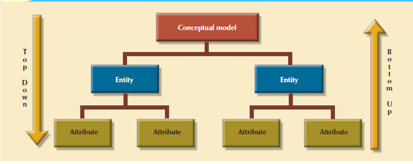
Figure 3.8.1(I) Top-down vs. bottom-up design sequencing
Q11) Explain Centralized Vs. Decentralized Design?
A11)
Centralized Vs. Decentralized Design
The two general approaches like bottom-up and top-down to database design are often influenced by factors like the scope and size of the system, the company’s management style, and therefore the company’s structure that's centralized or decentralized. Depending on such factors, the database design could also be supported two very different design philosophies: centralized and decentralized.
1. Centralized designis productive when the data component consists of a comparatively small number of objects and procedures. The design are carried out and represented during a fairly simple database. Centralized design is typical of relatively simple and/or small databases and may be successfully done by one person or by a little, informal design team.
The company operations and scope of the problem are limited to allow even a single designer to define the problem, create the conceptual design, verify the conceptual design with the user views, define system processes and data constraints to make sure the efficacy of the design, and make sure that the design will suits all the requirements. Following figure shows the centralized design architecture. A single conceptual design is completed and validated within the centralized design approach.
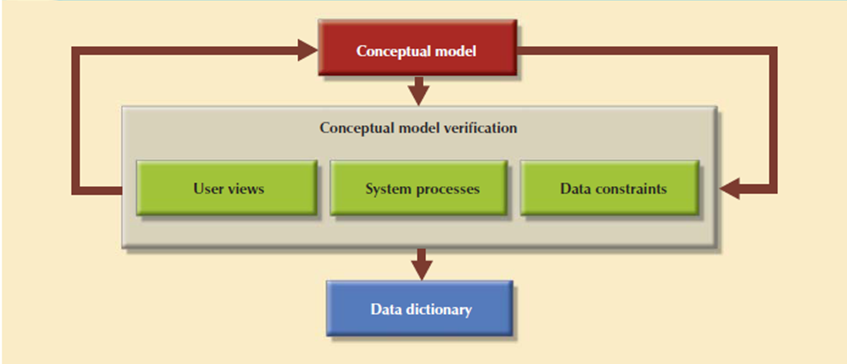
Figure 3.8.2(I) Centralized design Conceptual
2. Decentralized design used when the data component of the system features a number of entities and complex relations on which very complex operations are performed. Decentralized design is used when the problem itself is spread across several operational sites and every element is a subset of the whole data set.
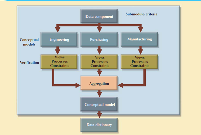
Figure 3.8.2(II) Decentralized design
In large and complicated projects, the database design can't be done by just one person. Instead, a carefully selected team of database designers is used to find a complex database project. Within the decentralized design framework, the database design task is split into several modules. Once the design criteria is formed, the lead designer assigns design subsets or modules to design groups within the team.
Because each design group focuses on modeling a subset of the system, the definition of boundaries and therefore the interrelation among data subsets is very precise. Each design group creates a conceptual data model like the subset being modeled. Each conceptual model is then verified individually against the user views, processes, and constraints for every of the modules. After the verification process has been completed, all modules are integrated into one conceptual model.
Because the data dictionary shows the characteristics of all objects within the conceptual data model, it has an important role within the integration process. The subsets are aggregated into a bigger conceptual model, the lead designer need to verify that the combined conceptual model is ready to support all of the specified transactions. The aggregation process needs the designer to make one model during which many aggregation problems need to address.