Unit – 1
Basic Real Time Concepts & Hardware Consideration
Q(1) Explain the Basic Terminology in Basic Real Time Concepts.
A 1)
Basic Terminology:
A system is a mapping of a set of inputs into a set of outputs.
The time between the presentation of a set of inputs to a system and the
realization of the required behaviour, including the availability of all associated outputs, is called the response time of the system.
A real - time system is a computer system that must satisfy bounded response -time constraints or risk severe consequences, including failure.
A real - time system is one whose logical correctness is based on both the
correctness of the outputs and their timeliness.
A failed system is a system that cannot satisfy one or more of the requirements stipulated in the system requirements specification.
An embedded system is a system containing one or more computers (or
processors) having a central role in the functionality of the system, but the
system is not explicitly called a computer.
A soft real - time system is one in which performance is degraded but not
destroyed by failure to meet response - time constraints.
A hard real - time system is one in which failure to meet even a single deadline may lead to complete or catastrophic system failure.
A firm real - time system is one in which a few missed deadlines will not lead
to total failure, but missing more than a few may lead to complete or catastrophic system failure.
Q(2) Explain A Sampling of Hard, Firm, and Soft Real - Time Systems.
A 2)
A Sampling of Hard, Firm, and Soft Real - Time Systems:
System | Real Time Classification | Explanation |
Avionics weapons delivery | Hard | Missing the deadline to launch the missile within a specified time after pressing the button may |
Navigation controller for | Firm | Missing a few navigation deadlines causes the robot to veer out from |
Console hockey game | Soft | Missing even several deadlines will |
Q(3) Explain Real Time Design Issues.
A 3)
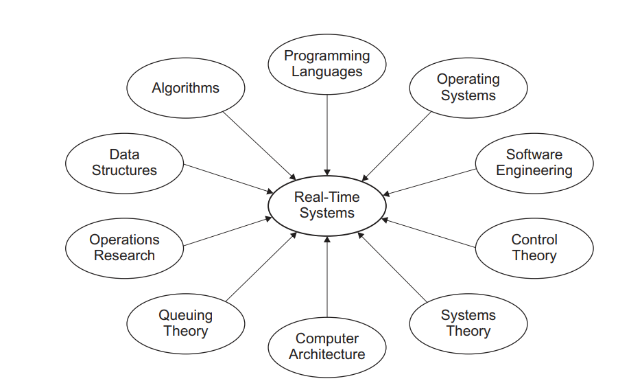
Fig.1: A variety of disciplines that affect real - time systems engineering
The design and implementation of real - time systems requires attention to
numerous practical issues. These include:
trade - off needed for a competitive solution, including dealing with
distributed computing systems and the issues of concurrency and
synchronization.
and the real - time implications resulting from their optimized compilation
into machine - language code.
and reliability through careful design and analysis.
hierarchy, and the selection of appropriate development tools and test
equipment.
An open system is an extensible collection of independently written applications that cooperate to function as an integrated system.
Q(4) Explain Practical Examples and Applications of Real-Time Systems
A 4)
Practical Examples and Applications of Real-Time Systems:
Domain | Applications |
Aerospace |
|
Civilian |
|
Industrial |
|
Medical |
|
Multimedia |
|
Q(5) Explain Brief History of Real Time Systems
A 5)
Brief History of Real Time Systems:
Year | Landmark | Developer | Development | Innovations |
1947 | Whirlwind | IBM | Flight Simulator | Ferrite Core Memory(“Fast”)High Level Language |
1957 | SAGE | IBM | Air Defense | Designed for Real Time |
1958 | Scientific 1103A | Univac | General Purpose | Asynchronous Interrupt |
1959 | SABRE | IBM | Airline Reservation | Hub-Go-Ahead Policy |
1962 | Basic Executive | IBM | General Purpose | Diverse Real Time Scheduling |
1963 | Basic Executive-II | IBM | General Purpose | Disk -resident system/User Programs |
1970s | RSX, RTE | DEC, HP | Real-time operating systems | Hosted By Mini-Computers |
1973 | Rate-Monotonic System | Liu & Leyland | Fundamental Theory | Upper bound on utilisation for schedulable systems |
1970s & 1980s | RMX-80, MROS 68K,VRTS,etc. | Various | Real-Time operating systems | Hosted by microprocessors |
1983 | Ada 83 | U.S. DoD | Programming Language | For mission-critical embedded systems |
1995 | Ada 95 | Community | Programming Language | Improved version of Ada 83 |
2000s | - | - | Various Advances in hardware,open-source,and commercial system software & tools | A continuously growing range of innovative applications that can be Real-Time |
Q(6) Explain Basic Architecture in details.
A 6)
Basic Architecture:
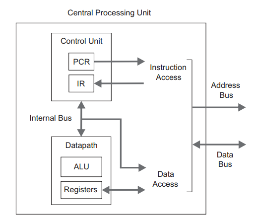
Fig.2: Internal structure of a simplified CPU. The Instruction Access and Data
The CPU is the core unit where instruction processing takes place; it consists of a control unit, an internal bus, and a data path, as illustrated in Above Figure.
(ALU), and a bank of work registers, as well as a status register.
Von-Newman Architecture:
Princeton architecture, is used in numerous commercial processors and can be depicted with only three elements: a central processing unit ( CPU), a system bus, and memory.
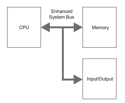
Fig.3. Von Neumann architecture with slightly enhanced system bus for programmed input/output.
Instruction Processing:
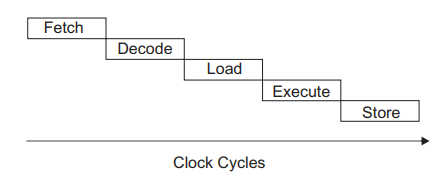
Fig.4.Phases of Instruction Processing vs. Clock Cycles
Q(7) Explain Peripheral Interfacing (I/O) in detail.
Ans-
Peripheral Interfacing (I/O):
• Polled I/O
• Interrupt - driven I/O
• Direct memory access
In a polled I/O system, the status of the I/O device is checked periodically, or, at least, regularly. Therefore, such I/O activity is software controlled; only accessible status and data registers are needed in the hardware side.
Interrupt - driven I/O processing has remarkable advantages over the straightforward polled I/O: the service latency can, in general, be reduced and made less uncertain without increasing the loading of the CPU.
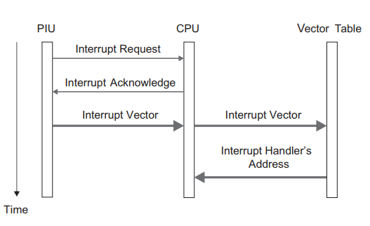
Fig.5: Interrupt - identification procedure between the CPU and PIU using vectored interrupt.
Analog and Digital Input/Output:
Q(8) Explain Memory in detail.
A 8)
Memory:
• Fast page mode ( FPM ) DRAM
• Extended data output ( EDO ) DRAM
• Synchronous DRAM ( SDRAM )
• Direct Rambus DRAM ( DRDRAM
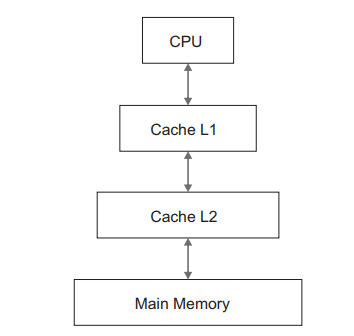
Fig.6: Hierarchical memory organization with two cache levels, L1 and L2, between the CPU and main memory.
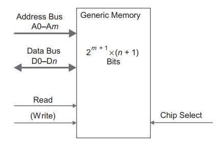
Fig.7: Interface lines of a generic memory component
Q(9) Explain Memory in detail.
A 9)
Memory:
• Fast page mode ( FPM ) DRAM
• Extended data output ( EDO ) DRAM
• Synchronous DRAM ( SDRAM )
• Direct Rambus DRAM ( DRDRAM )
Double data rate 3 synchronous DRAM ( DDR3 SDRAM )
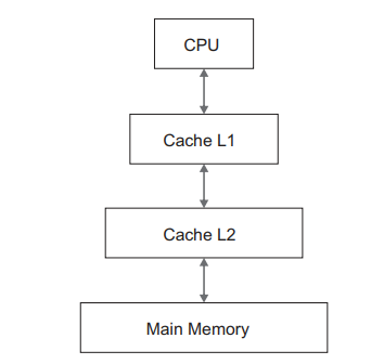
Fig.6: Hierarchical memory organization with two cache levels, L1 and L2, between the CPU and main memory.
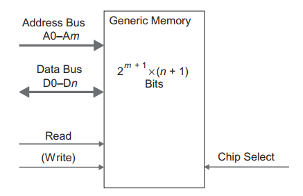
Fig.7: Interface lines of a generic memory component
Q(10) Explain Cache and Direct Memory Access in detail.
A 10)
Cache:
Direct Memory Access:
in the system without any CPU intervention.