Unit – 2
Real Time specification and design Techniques
Q(1) Explain the basic Languages in RTOS.
A 1)
Languages:
- Natural languages are the languages that people speak, such as English, Spanish, and French.
- They were not designed by people (although people try to impose some order on them); they evolved naturally.
2. Formal Languages:
3. Programming Languages:
Programming languages are formal languages that have been designed to express computations.
Q(2) Explain the flowchart for steps of a process in sequential order.
A 2)
Flowcharts:
Flowchart Symbol | Name | Description |
| Process symbol | Also known as an “Action Symbol,” this shape represents a process, action, or function. It’s the most widely-used symbol in flowcharting. |
| Start/End symbol | Also known as the “Terminator Symbol,” this symbol represents the start points, end points, and potential outcomes of a path. Often contains “Start” or “End” within the shape. |
| Document symbol | Represents the input or output of a document, specifically. Examples of and input are receiving a report, email, or order. Examples of an output using a document symbol include generating a presentation, memo, or letter. |
| Decision symbol | indicates a question to be answered — usually yes/no or true/false. The flowchart path may then split off into different branches depending on the answer or consequences thereafter. |
| Connector symbol | Usually used within more complex charts, this symbol connects separate elements across one page. |
| Off-Page Connector/Link symbol | Frequently used within complex charts, this symbol connects separate elements across multiple pages with the page number usually placed on or within the shape for easy reference. |
| Input/Output symbol | Also referred to as the “Data Symbol,” this shape represents data that is available for input or output as well as representing resources used or generated. While the paper tape symbol also represents input/output, it is outdated and no longer in common use for flowchart diagramming. |
| Comment/Note symbol | Placed along with context, this symbol adds needed explanation or comments within the specified range. It may be connected by a dashed line to the relevant section of the flowchart as well. |
Q(3) Explain the Structured charts in detail.
A 3)
Structured charts 
Fig.1 Structured charts
Q(4) Explain the Symbols used in construction of structured chart in detail.
A 4)
Symbols used in construction of structured chart:
It represents the process or task of the system. It is of three types.
A control module branches to more than one sub module.
Sub Module is a module which is the part (Child) of another module.
Library Module are reusable and invokable from any module.

Fig.2
2. Conditional Call:
It represents that control module can select any of the sub module on the basis of some condition.
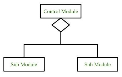
Fig.3
3. Loop (Repetitive call of module):
It represents the repetitive execution of module by the sub module.
A curved arrow represents loop in the module.

Fig.4
All the sub modules cover by the loop repeat execution of module.
4. Data Flow:
It represents the flow of data between the modules. It is represented by directed arrow with empty circle at the end.

Fig.5
5. Control Flow:
It represents the flow of control between the modules. It is represented by directed arrow with filled circle at the end.

Fig.6
6. Physical Storage:
Physical Storage is that where all the information are to be stored.
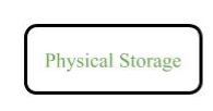
Example: Structure chart for an Email server :
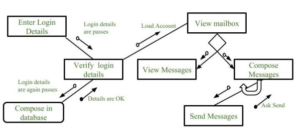
Fig.6
Q(5) Explain the Pseudo code and Programming Design Languages in detail.
A 5)
Pseudo code and Programming Design Languages:
Pseudo code:
Note: Pseudo code is not an actual programming language:
FUNCTION linear Search (list, search Term):
FOR index FROM 0 -> length (list):
IF list [index] == search Term THEN
RETURN index
ENDIF
ENDLOOP
RETURN -1
END FUNCTION
2.3.2 Program:
Program for Linear Search :
// C++ code for linearly search x in arr[]. If x
// is present then return its location, otherwise
// return -1
int search(int arr[], int n, int x)
{
int i;
for (i = 0; i < n; i++)
if (arr[i] == x)
return i;
return -1;
}
Q(6) Explain the Warnier-Orr diagram in detail.
A 6)
Warnier-Orr diagram:
A Warnier-Orr diagram (also known as a logical construction of a program/system) is a kind of hierarchical flowchart that allows the description of the organization of data and procedures.
Each step in turn is further defined. the result on the next level.
They are: Yet they are powerful design tools. that must be passed from level to level. In addition, the sequence of working backwards . This method is useful for both data and process definition.
Q(7) Explain the Nondeterministic Finite Automata (NFA) in detail.
A 7)
Nondeterministic Finite Automata (NFA) :
1. Null (or ε) move is allowed i.e., it can move forward without reading symbols.
2. Ability to transmit to any number of states for a particular input.
δ: Transition Function
δ: Q X (Σ U ε ) --> 2 ^ Q.
For example, below is a NFA for above problem:
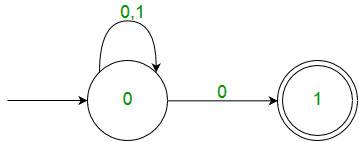
Fig.7 NFA
One important thing to note is, in NFA, if any path for an input string leads to a final state, then the input string accepted. For example, in above NFA, there are multiple paths for input string “00”. Since, one of the paths leads to a final state, “00” is accepted by above NFA.
Q(8) Explain the Deterministic Finite Automata (NFA) in detail.
A 8)
Deterministic Finite Automata (DFA) :
Q : set of all states.
Σ : set of input symbols. (Symbols which machine takes as input)
q : Initial state. (Starting state of a machine)
F : set of final state.
δ : Transition Function, defined as δ : Q X Σ --> Q.
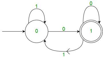
Fig.8: DFA with Σ = {0, 1}
One important thing to note is, there can be many possible DFAs for a pattern. A DFA with minimum number of states is generally preferred.
Q(9) Explain the Finite State Automata in detail.
A 9)
Finite State Automata:

Fig.9: Features of Finite Automata
The above figure shows following features of automata:
A Finite Automata consists of the following:
Q: Finite set of states.
Σ: set of Input Symbols.
q: Initial state.
F: set of Final States.
δ: Transition Function.
Formal specification of machine is
{Q, Σ, q, F, δ}.
Q(10) Explain the Comparison of DFA & NFA in detail.
A 10)
Comparison of DFA & NFA:


