Unit 4
Logic and Program Control Instruction
Q1) Explain shift instructions?
A1) SHR : Shift Right
The SHR instruction is an abbreviation for ‘Shift Right’. This instruction simply shifts the mentioned bits in the register to the right side one by one by inserting the same number (bits that are being shifted) of zeroes from the left end. The rightmost bit that is being shifted is stored in the Carry Flag (CF).
Syntax: SHR Register, Bits to be shifted
Example: SHR AX, 2
Working:

2) SAR : Shift Arithmetic Right
The SAR instruction stands for ‘Shift Arithmetic Right’. This instruction shifts the mentioned bits in the register to the right side one by one, but instead of inserting the zeroes from the left end, the MSB is restored. The rightmost bit that is being shifted is stored in the Carry Flag (CF).
Syntax: SAR Register, Bits to be shifted
Example: SAR BX, 5
Working:

3) SHL : Shift Left
The SHL instruction is an abbreviation for ‘Shift Left’. This instruction simply shifts the mentioned bits in the register to the left side one by one by inserting the same number (bits that are being shifted) of zeroes from the right end. The leftmost bit that is being shifted is stored in the Carry Flag (CF).
Syntax: SHL Register, Bits to be shifted
Example: SHL AX, 2
Working:

4) SAL : Shift Arithmetic Left
The SAL instruction is an abbreviation for ‘Shift Arithmetic Left’. This instruction is the same as SHL.
Syntax: SAL Register, Bits to be shifted
Example: SAL CL, 2
Working:

Q2) Explain rotate instructions?
A2) ROL : Rotate Left
The ROL instruction is an abbreviation for ‘Rotate Left’. This instruction rotates the mentioned bits in the register to the left side one by one such that leftmost bit that is being rotated is again stored as the rightmost bit in the register, and it is also stored in the Carry Flag (CF).
Syntax: ROL Register, Bits to be shifted
Example: ROL AH, 4
Working:

6) ROR : Rotate Right
The ROR instruction stands for ‘Rotate Right’. This instruction rotates the mentioned bits in the register to the right side one by one such that rightmost bit that is being rotated is again stored as the MSB in the register, and it is also stored in the Carry Flag (CF).
Syntax: ROR Register, Bits to be shifted
Example: ROR AH, 4
Working:

7) RCL : Rotate Carry Left
This instruction rotates the mentioned bits in the register to the left side one by one such that leftmost bit that is being rotated it is stored in the Carry Flag (CF), and the bit in the CF moved as the LSB in the register.
Syntax: RCL Register, Bits to be shifted
Example: RCL CH, 1
Working:

8) RCR : Rotate Carry Right
This instruction rotates the mentioned bits in the register to the right side such that rightmost bit that is being rotated it is stored in the Carry Flag (CF), and the bit in the CF moved as the MSB in the register.
Syntax: RCR Register, Bits to be shifted
Example: RCR BH, 6
Working:

Q3) Explain conditional jump instruction?
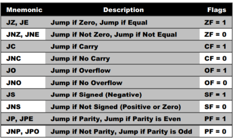
A3) Conditional Jump Instruction has the following syntax:

jumps based on the value of CX and ECX:

Q4) Explain signed jump instruction?
A4)

Q5) Explain unsigned jump instruction?
A5)

Q6) Explain machine control instructions?
A6)
Machine Control Instructions
1.NOP (No operation)
2. HLT (Halt)
3. DI (Disable interrupts)
4. EI (Enable interrupts)
5. SIM (Set interrupt mask)
6. RIM (Reset interrupt mask)
NOP (No operation) –
Opcode- NOP
Operand- None
Length- 1 byte
M-Cycles- 1
T-states- 4
Hex code- 00
It is used when no operation is performed. No flags are affected during the execution of NOP. The instructon is used to fill in time delay or to delete and insert instructions while troubleshooting.
HLT (Halt and enter wait state) –
Opcode- HLT
Operand- None
Length- 1 byte
M-Cycles- 2 or more
T-states- 5 or more
Hex code- 76
The Microprocessor finishes executing the current instruction and halts any further execution. The contents of the registers are unaffected during the HLT state.
DI (Disable interrupts) –
Opcode- DI
Operand- None
Length- 1 byte
M-Cycles- 1
T-states- 4
Hex code- F3
Disable interrupt is used when the execution of a code sequence cannot be interrupted. For example, in critical time delays, this instruction is used at the beginning of the code and the interrupts are enabled at the end of the code. The 8085 TRAP cannot be disabled.
EI (Enable interrupts) –
Opcode- EI
Operand- None
Length- 1 byte
M-Cycles- 1
T-states- 4
Hex code- FB
After a system reset or the acknowledgement of an interrupt, the Interrupt Enable the flip-flop is reset, thus disabling the interrupts.
SIM (Set interrupt mask) –
Opcode- SIM
Operand- None
Length- 1 byte
M-Cycles- 1
T-states- 4
Hex code- 30
This SIM instruction is used to implementation of different interrupts of 8085 microprocessor like RST 7.5, 6.5 and 5.5 and also serial data output. It does not affect TRAP interrupt.
RIM (Reset interrupt mask) –
Opcode- RIM
Operand- None
Length- 1 byte
M-Cycles- 1
T-states- 4
Hex code- 20
This is a multipurpose instruction used to read the status of 8085 interrupts 7.5, 6.5, 5.5 and to read serial data input bit.
Q7) Explain basic interrupt processing?
A7) An interrupt is the method of processing the microprocessor by peripheral device. An interrupt is used to cause a temporary halt in the execution of program.
Microprocessor responds to the interrupt with an interrupt service routine, which is short program or subroutine that instructs the microprocessor on how to handle the interrupt.
There are two basic type of interrupt, maskable and non-maskable, non-maskable interrupt requires an immediate response by microprocessor, it usually used for serious circumstances like power failure.
A maskable interrupt is an interrupt that the microprocessor can ignore depending upon some predetermined upon some predetermined condition defined by status register.
Q8) Explain the types of interrupts?
A8) Interrupt can divide to five groups:
1. hardware interrupt
2. Non-maskable interrupt
3. Software interrupt
4. Internal interrupt
5. Reset
Hardware, software and internal interrupt are service on priority basis. each interrupt is given a different priority level by assign it a type number.
Type 0 identifies the highest-priority and type 255 identifies the lowest- priority interrupt. The 80x86 chips allow up to 256 vectored interrupts.
This means that up to 256 different sources for an interrupt and the 80x86 will directly call the service routine for that interrupt without any software processing. In non-vectored interrupts that transfer control directly to a single interrupt service routine, regardless of the interrupt source.
The 80x86 provides a 256 entry interrupt vector table beginning at address 0:0 in memory. This is a 1K table containing 256 4-byte entries.
Each entry in this table contains a segmented address that points at the interrupt service routine in memory.
The lowest five types are dedicated to specific interrupts such as the divide by zero interrupt and the non- maskable interrupt.
The next 27 interrupt types, from 5 to 31 are High priority 3 reserved by Intel for use in future microprocessors. The upper 224 interrupt types, from32 to 255, are available to use for hardware and software interrupts.
Q9) What happens when interrupt occurs?
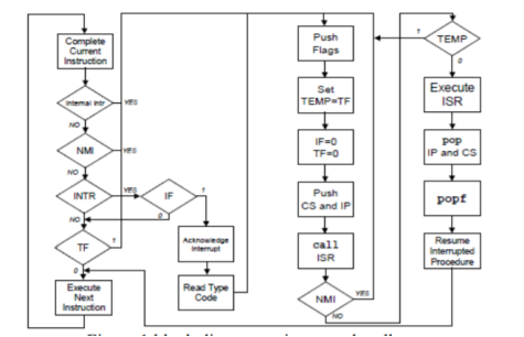
A9) When an interrupt occurs as shown in figure regardless of source, the 80x86 does the following:
1. The CPU pushes the flags register onto the stack.
2. The CPU pushes a far return address (segment:offset) onto the stack, segment value first.
3. The CPU determines the cause of the interrupt that is the interrupt number
and fetches the four byte interrupt vector from address 0:vector*4.
4. The CPU transfers control to the routine specified by the interrupt vector table entry.

When the interrupt service routine wants to return control, it must execute an IRET (interrupt return) instruction.
The interrupt return pops the far return address and the flags off the stack. Note that executing a far return is insufficient since that would leave the flags on the stack.
Q10) What are hardware interrupts?
A10) Hardware interrupt is caused by any peripheral device by sending a signal through a specified pin to the microprocessor.
The 8086 has two hardware interrupt pins, i.e. NMI and INTR. NMI is a non-maskable interrupt and INTR is a maskable interrupt having lower priority. One more interrupt pin associated is INTA called interrupt acknowledge.
NMI
It is a single non-maskable interrupt pin (NMI) having higher priority than the maskable interrupt request pin (INTR)and it is of type 2 interrupt.
When this interrupt is activated, these actions take place −
INTR
The INTR is a maskable interrupt because the microprocessor will be interrupted only if interrupts are enabled using set interrupt flag instruction. It should not be enabled using clear interrupt Flag instruction.
The INTR interrupt is activated by an I/O port. If the interrupt is enabled and NMI is disabled, then the microprocessor first completes the current execution and sends ‘0’ on INTA pin twice. The first ‘0’ means INTA informs the external device to get ready and during the second ‘0’ the microprocessor receives the 8 bit, say X, from the programmable interrupt controller.
These actions are taken by the microprocessor −