UNIT 4
Object Oriented Design with UML
Q1) Elaborate Object oriented design?
A1)
Object oriented design is the result of focusing attention not on the function performed by the program, but instead on the data that are to do manipulated by the program Thus, it is orthogonal to function oriented design. It starts with an examination of the real world “things” that are part of the problem to be solved These things (which we will call objects) are characterized individually in terms of their attributes and behaviour.
Basic Concepts on which Objects are based:
Q2) Explain UML Diagrams & Design patterns?
A2)
The UML stands for Unified modelling language, is a standardized visual modelling language used for specifying and visualizing to construct, and document a primary artifacts of the software system. It helps in Object oriented designing and characterizing of system. It explains both software and hardware working of systems.
UML-Building Blocks
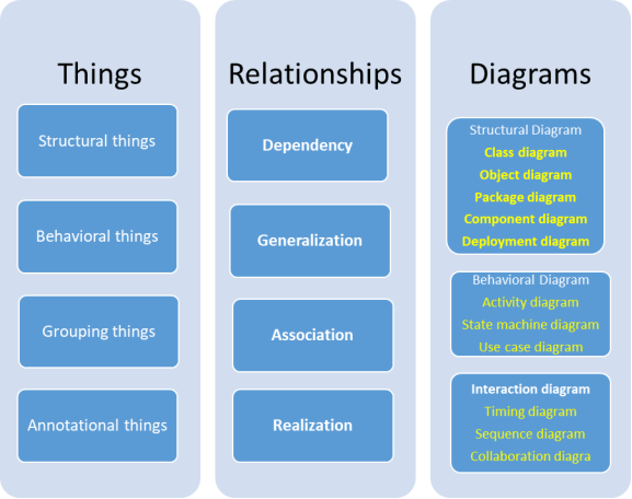
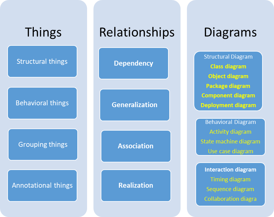
UML is composed of three main building blocks. The basic UML building blocks are summarized in block diagram.
It has a collection of five types of views:

A UML DIAGRAM

Q3) What are object diagrams? Explain the need of object diagrams?
A3)
Object diagrams are derived from class diagrams so object diagrams are dependent upon class diagrams. These diagrams represent an instance of a class diagram. The basic concepts are similar for class diagrams and object diagrams. Object diagrams also represent the static view of a system but this static view is a snapshot of the system at a particular moment. They are used to render a set of objects and their relationships as an instance.
Purpose of Object Diagrams
The purpose of a diagram should be understood clearly to implement it practically. The purposes of object diagrams are similar to class diagrams.The difference is that a class diagram represents an abstract model consisting of classes and their relationships. However, an object diagram represents an instance at a particular moment, which is concrete in nature.It means the object diagram is closer to the actual system behavior. The purpose is to capture the static view of a system at a particular moment.
The purpose of the object diagram can be summarized as –

Q4) Explain component diagrams in detail?
A4)
Component diagrams are different in terms of nature and behavior. Component diagrams are used to model the physical aspects of a system. Now the question is, what are these physical aspects? Physical aspects are the elements such as executables, libraries, files, documents, etc. which reside in a node.
Component diagrams are used to visualize the organization and relationships among components in a system. These diagrams are also used to make executable systems.
Purpose of Component Diagrams
Component diagram is a special kind of diagram in UML. The purpose is also different from all other diagrams discussed so far. It does not describe the functionality of the system but it describes the components used to make those functionalities.Thus from that point of view, component diagrams are used to visualize the physical components in a system. These components are libraries, packages, files, etc.
Component diagrams can also be described as a static implementation view of a system. Static implementation represents the organization of the components at a particular moment.
A single component diagram cannot represent the entire system but a collection of diagrams is used to represent the whole.
The purpose of the component diagram can be summarized as −

Q5) Explain Deployment diagrams in detail with example?
A5)
Deployment are used to visualize the topology of the physical components of a system, where the software components are deployed and used to describe the static deployment view of a system. Deployment diagrams consist of nodes and their relationships.
Purpose of Deployment Diagrams
The term Deployment itself describes the purpose of the diagram. Deployment diagrams are used for describing the hardware components, where software components are deployed. Component diagrams and deployment diagrams are closely related.
Component diagrams are used to describe the components and deployment diagrams shows how they are deployed in hardware.
UML is mainly designed to focus on the software artifacts of a system. However, these two diagrams are special diagrams used to focus on software and hardware components.
Most of the UML diagrams are used to handle logical components but deployment diagrams are made to focus on the hardware topology of a system. Deployment diagrams are used by the system engineers.
The purpose of deployment diagrams can be described as −

Q6) Give Difference Between Structured and Object-oriented analysis?
A6)
STRUCTURED ANALYSIS | OBJECT-ORIENTED ANALYSIS |
The main focus is on process and procedures of system. | The main focus in on data structure and real-world objects that are important. |
It uses (SDLC) method for different purposes like planning, analyzing, designing, implementing, and supporting an information system. | It uses Incremental or Iterative methodology to refine and extend our design. |
It is suitable for well-defined projects with stable user requirements. | It is suitable for large projects with changing user requirements. |
Risk while using this analysis technique is high and reusability is also low. | Risk while using this analysis technique is low and reusability is also high. |
Structuring requirements include DFDs (Data Flow Diagram), Structured English, ER (Entity Relationship) diagram, CFD (Control Flow Diagram), Data Dictionary, Decision table/tree, State transition diagram. | Requirement engineering includes Use case model (find Use cases, Flow of events, Activity Diagram), the Object model (find Classes and class relations, Object interaction, Object to ER mapping), Statechart Diagram, and deployment diagram. |
This technique is old and is not preferred usually. | This technique is new and is mostly preferred. |
Q7) Write short notes on Class Diagram, Composite Structure, Diagram Object, Diagram Component, Diagram Deployment Diagram?
A7)
a) Class Diagram – The most widely use UML diagram is the class diagram. It is the building block of all object oriented software systems. We use class diagrams to depict the static structure of a system by showing system’s classes, their methods and attributes. Class diagrams also help us identify relationship between different classes or objects.
b) Composite Structure Diagram – We use composite structure diagrams to represent the internal structure of a class and its interaction points with other parts of the system. A composite structure diagram represents relationship between parts and their configuration which determine how the classifier (class, a component, or a deployment node) behaves. They represent internal structure of a structured classifier making the use of parts, ports, and connectors. We can also model collaborations using composite structure diagrams. They are similar to class diagrams except they represent individual parts in detail as compared to the entire class.
c) Object Diagram – An Object Diagram can be referred to as a screenshot of the instances in a system and the relationship that exists between them. Since object diagrams depict behaviour when objects have been instantiated, we are able to study the behaviour of the system at a particular instant. An object diagram is similar to a class diagram except it shows the instances of classes in the system. We depict actual classifiers and their relationships making the use of class diagrams. On the other hand, an Object Diagram represents specific instances of classes and relationships between them at a point of time.
d) Component Diagram – Component diagrams are used to represent the how the physical components in a system have been organized. We use them for modelling implementation details. Component Diagrams depict the structural relationship between software system elements and help us in understanding if functional requirements have been covered by planned development. Component Diagrams become essential to use when we design and build complex systems. Interfaces are used by components of the system to communicate with each other.
e) Deployment Diagram – Deployment Diagrams are used to represent system hardware and its software. It tells us what hardware components exist and what software components run on them.We illustrate system architecture as distribution of software artefacts over distributed targets. An artefact is the information that is generated by system software. They are primarily used when a software is being used, distributed or deployed over multiple machines with different configurations.
f) Package Diagram – We use Package Diagrams to depict how packages and their elements have been organized. A package diagram simply shows us the dependencies between different packages and internal composition of packages. Packages help us to organise UML diagrams into meaningful groups and make the diagram easy to understand. They are primarily used to organise class and use case diagrams.
Behaviour Diagrams