UNIT - 2
Assemblers
Q1) Explain A simple assembly scheme, pass structure of assemblers?
A1)
A simple Assembly Scheme: -
In a simply assembly scheme each statement has two operands: -
a. First Operand is always a register which can be any one of AREG, BREG, CREG, & DREG.
b. Second Operand refers to memory word using a symbolic name and operation displacement.
Pass Structure of Assembler: -
1. The work of assembler is in a program to convert instruction written in low level assembly code into relocatable machine code and generating information for the loader.
2. Assembler generates instruction of symbols or mnemonics in Operation field and find the values of symbol to produce machine code.
3. If assembler does this work in one scan or in a single scan then it is called single pass assembler.
4. If assembly takes multiple scans then called multiple pass assemblers
Single Pass Assembler: -
1. Single pass assembler defines symbols and literals and separates the symbol, mnemonic opcode & operand fields.
2. Single pass assembler will perform analysis.
3. It builds the symbol table and literal table to remember them respectively.
4. Keep track of location counter (LC) and perform processing.
5. Process pseudo-operations and construct intermediate representation.
Two Pass Assembler: -
1. Two pass assembler forwards references easily and uses symbol table, IR (Instruction Register) and gives TP (Target Program).
2. Two pass assembler generates object code by converting symbolic opcode into respective numeric opcode.
3. It generates data for literals and look for values of symbol.
4. We can say that synthesis is performed by second pass assembler.
Q2) Explain Design of a two pass assembler?
A2)
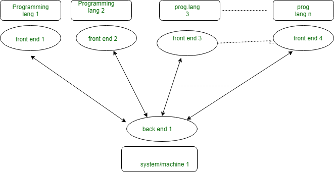
A 2 pass/multi-pass Compiler is that of a sort of the compiler which will processes that of the ASCII text file or abstract that of the syntax tree of a program persistently. In multipass Compiler we tend to divide phases in 2 pass as:
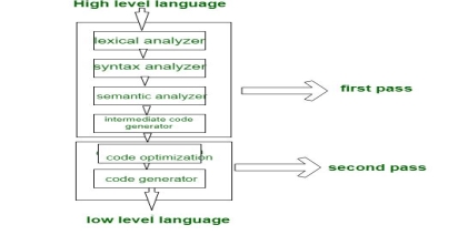
1. 1st Pass: is refers as
o (a). Front end
o (b). Analytic half
o (c). Platform freelance
In 1st pass the enclosed phases are as Lexical analyzer, syntax analyzer, linguistics analyzer, intermediate code generator are work as face and analytic part suggests that all parts analyse the High level language and convert them that of the 3 address code and 1st pass is that of the platform freelance thanks to the output of first pass is as three of the address code that is beneficial for each system which of the necessity is to vary the code improvement and code generator phase which are involves the second pass.
2. Second Pass: is refers as
o (a). Back end
o (b). Synthesis half
o (c). Platform Dependent
In second Pass the enclosed phases are that as Code improvement which of the Code generator are work as backside Associate in Nursingd that of the synthesis half refers to it of taking input as 3 address code and so convert them into that of the Low level language/assembly language and second pass is that of the platform dependent thanks to the ultimate stage of a typical compiler converts that of the intermediate illustration of the program into an possible set of that of the directions that relies thereon of the system.
With multi-pass Compiler we will solve these two basic problems:
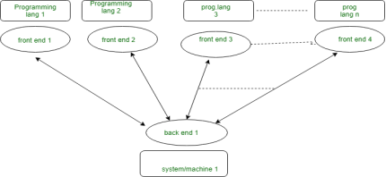
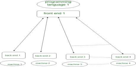
2. If we wish to style a compiler for same programing language for various machine/system. during this case we tend to create different backside for various Machine/system and make just one face for same programing language as:
Differences between Single Pass and Multipass Compilers:
Parameters Single pass multi Pass
Speed quick Slow
Memory a lot of Less
Time Less a lot of
Portability No affirmative
Q3) Explain A single pass assembler for IBM PC?
A3)
A single pass assembler for IBM PC
Focuses on the design features for handling the forward reference problem in an environment using segment-based addressing.
Architecture of Intel 8088.
Intel 8088 Instructions.
Assembly Language of Intel 8088.
Problems of Single pass assembly
Design of the Assembler.
Q4) Explain The Architecture of Intel 8088?
A4)
Supports 8 and 16 bit arithmetic. Provides special instructions for string manipulation.
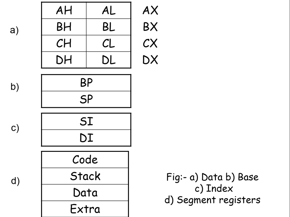
The CPU contains following features –
1. Data registers AX, BX, CX and DX
2. Index registers SI and DI
3. Stack pointer registers BP and SP
4. Segment registers Code, Stack, Data and Extra.
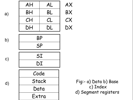
Each data register is 16 bits in size, split into upper and lower halves.
Either half can be used for 8 bit arithmetic, while the two halves together constitute the data register for 16 bit arithmetic.
Architecture supports stacks for storing subroutine and interrupts return addresses, parameters and other data.
The index registers SI and DI are used to index the source and destination addresses in string manipulation instructions.
Two stack pointer registers called SP and BP are provided to address the stack. Push and Pop instructions are provided.
The Intel 8088 provides addressing capability for 1 MB of primary memory.
The memory is used to store three components of program, Program code, Data and Stack.
The Code, Stack and Data segment registers are used to contain the start addresses of these three components.
The Extra segment registers points to another memory area which can be used to store data.
The size of each segment is limited to 216 i.e. 64 K bytes.
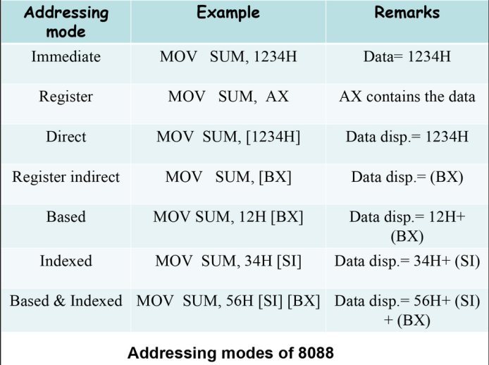
The 8088 architecture provides 24 addressing modes.
In the Immediate addressing mode, the instruction itself contains the data that is to participate in the instruction. This data can be 8 or 16 bits in length.
In the Direct addressing mode, the instruction contains 16 bit number which is taken to be displacement from the segment base contained in segment register.
In the Indexed mode, contents of the index register indicated in the instruction ( SI or DI ) are added to the 8 or 16 bit displacement contained in the instruction.
In the Based mode, contents of the base register are added to the displacement.
The based-and-indexed with displacement mode combines the effect of the based and indexed modes.
Q5) Explain Intel 8088 Instructions?
A5)
Arithmetic Instructions
Operands can be in one of the four 16 bit registers or in memory location designated by one of the 24 addressing modes.
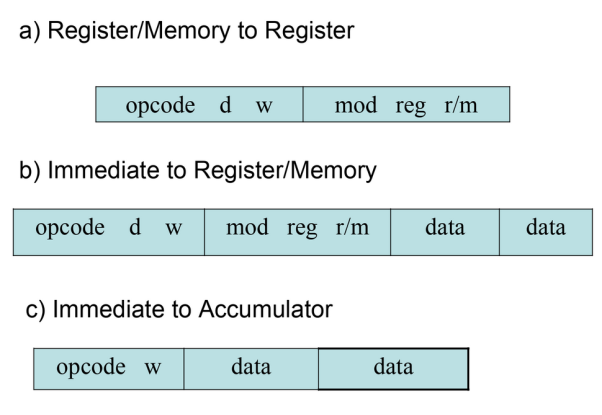
Three instruction formats are as shown in figure.
The mod and r/m fields specify first operand, which can be in register or in memory.
The reg field describes the second operand, which is always a register.
The instruction opcode indicates which instruction format is applicable.
The direction field (d) indicates which operand is the destination operand.
If d=0, the register/memory operand is the destination, else the register operand indicated by reg is the destination.
The width field (w) indicates whether 8 or 16 bit arithmetic is to be used.
Note 1: (BP)+ DISP for indirect addressing, d16 for direct
Note 2: Same as previous column, except d16 instead of d8

Control Transfer Instructions
Two groups of control transfer instructions are supported.
1. Calls, jumps and returns
2. Iteration control instructions
Calls, jumps and returns can occur within the same segment or can cross segment boundaries.
Intra-segment transfers are preferably assembled using a self-relative displacement.
The longer form of intra-segment transfers uses a 16 bit logical address within the segment.
Inter-segment transfers indicate a new segment base and an offset.
Iteration control operations perform looping decisions in string operations.
Example:- Consider the program
MOV SI, 100H ; Source address
MOV DI, 200H ; Destination address
MOV CX, 50H ; No. of bytes
CLD ; Clear direction flag
REP MOVSB ; Move 80 bytes
Q6 Explain The Assembly Language of Intel 8088?
A6)
1) Statement Format
[Label:] opcode operand(s) ; comment string
2) Assembler Directives
a) Declarations
- Declaration of constants and reservation of storage are both achieved in the same direction
A DB 25 ; Reserve byte & initialize
B DW ? ; Reserve word, no initialization
C DD 6DUP(0) ; 6 Double words, all 0’s
b) EQU and PURGE
EQU defines symbolic names to represent values
PURGE undefined the symbolic names. That name can be reused for other purpose later in the program.
Example:-
XYZ DB ?
ABC EQU XYZ ; ABC represents name XYZ
PURGE ABC ; ABC no longer XYZ
ABC EQU 25 ; ABC now stands for ‘25’
Q7) Draw 55 Instruction Format?
A7)
opcode L B1 D1 B2 D2
0 7 8 15 16 19 20 31 32 35 36 47
It is a 6 byte instruction used to move L+I bytes data fro the storage locationi to the storage location2.
Storage location1 = D1+[B1]
Storage location2 = D2+[B2]
Eg: MOV 60,400(3),500(4)
Q8) Define Indirect Addressing?
A8)
In the case of immediate addressing the operand field gives the memory location. The word from the given address is fetched and it gives the address of the operand.
Eg:ADD R5, [600]
Here the second operand is given in indirect addressing mode. First the word in memory location 600 is fetched and which will give the address of the operand.
Q9) What Is The Name Of A And L Register In Sic Machine And Also Specify Its Use?
A9)
A-accumulator: Used for arithmetic operation. i.e., in the case of arithmetic operations one operand is in the accumulator, and other operand may be an immediate value, register operand or memory content. The operation given in the instruction is performed and the result is stored in the accumulator register.
L-linkage register: It is used to store the return address in the case of jump to subroutine (JSUB) instructions.
Q10) That Is The Difference Between The Instructions Lda # 3 And Lda Three?
A10)
In the first instruction immediate addressing is used. Here the value 3 is directly loaded into the accumulator register. In the second instruction the memory reference is used. Here the address(address assigned for the symbol THREE) is loaded into the accumulator register.