OOMD
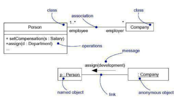
Unit-5Behavioral Modeling using UML Q1) What do you mean by interaction?A1) Interactions An interaction is a behavior that comprises a series of messages exchanged within a context between a set of objects to achieve a goal. A message is a definition of a communication between objects that transmits data with the intention that action will take place. Context Wherever objects are related to each other, you can find an interaction. In the collaboration of objects which exist in the context of your system or subsystem, you'll find interactions. In the framework of an activity, you can also find interactions. Finally, in the sense of a class, you'll notice interactions. Very frequently, in the cooperation between artefacts that reside in the sense of your device or subsystem as a whole, you can find interactions. In the implementation of an event, you'll also find interactions between objects. An operation's parameters, any local variables to the operation, and any global objects to the operation (but still visible to the operation) may communicate with each other to perform the implementation algorithm of that operation. Finally, in the sense of a class, you can notice interactions. To imagine, define, build, and log the semantics of a class, you can use interactions. Objects and Roles Either concrete things or prototypical things are the objects that engage in an interaction. As a concrete entity, in the physical world, an object represents something. You can find instances of groups, modules, nodes, and use cases in the sense of an interaction. Although there may be no clear instances of abstract classes and interfaces by definition, you may find instances of these things in an interaction. These instances do not represent direct instances of the abstract class or of the interface, but may represent indirect (or prototypical) instances, respectively, of some specific child of the abstract class of a particular class who understands the interface. Links A relation is a connection between objects that is semantic. A relation is, in general, an instance of an association. There may be a connection between the instances of the two classes if a class has an interaction with another class; wherever there is a link between two objects, one object may send a message to the other object. A relation defines a path through which a message can be sent to another (or the same) object by one object.
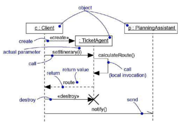
Fig 1: links and associations Message A message is the specification of a communication between objects that conveys data with the intention of the outcome of the operation. The receipt of an example of a message can be called an instance of an occurrence. The operation that occurs when you move a message is an executable statement that forms an abstraction of a computational method. A change of state can result from an action.
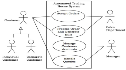
Fig 2: message Q2) Write about use cases?A2) Use Cases● Use case modeling was developed by ivar Jacobson based on his experience and expertise.● Use case modeling describes what function the system provides to its user.● It also provides who are the users of the system.● It is created by the discussion between the developers & customers or the end user.● Use case modeling shows use case view of the system● It influences both logical & physical architecture because use case are implemented in this architecture.● Use case modeling contains the basic building blocks as use cases, actors, system boundary or subject.● Use cases specify the function of the system.● It consists of use case diagrams.● Actors are the external entities which are going to use the function of the system.● System boundary or subject encapsulated all the use cases Q3) Explain a use case diagram?A3) Use Case Diagram To represent a system's dynamic behavior, a use case diagram is used. It encapsulates the functionality of the system by adding instances of usage, actors, and their relationships. It models the activities, resources, and functions required by an application's system/subsystem. It portrays a system's high-level features and also tells how a system is treated by the user. Use case diagrams show an external view of the actions of the elements in a structure and how they can be used in context. Using case diagrams made up of − ● Use cases● Actors● Relationships like dependency, generalization, and association Case diagrams of usage are used - ● To model the context of a system by enclosing all the actions of a system within a rectangle and by communicating with it, to concentrate on the actors outside the system. ● To model a system's specifications from an outside point of view.
Fig 3: example of use casesUse cases ● Use case is defined as a sequence of actions performed by a system.● Use case is the function that the system performs for an actor.● It is something that an actor wants a system to perform● These are the functions performed by the system or subsystem by interacting with the external entity such as an actor.● Typically use cases are initiated by an actor.● Use cases provide value to the actors.● It must be complete which provides a complete description.● It is a classifier which describes the complete functionally as a whole including any alternative exception or error during the execution of the use case.● Use cases are connected to actors via association relationship.● Association shows which use case is imitated by which actor.● The UML notification for use case as follows.
Fig 4: example of use cases ● It is represented in UML as an ellipse containing the name of the use case.● Use cases are placed inside the system boundary & connected to an actor through association. Actor ● Actor is the user of the system.● Actor is something or someone who uses the system functions.● Actor is the one who exchanges messages with the system.● An actor can be a human or computer or another system.● An actor is a classifier which represents a role not an individual user of the system.Ex. If xyz want to borrow books from the libraries then instead of xyz its role as borrower will be modeled as an actor.● An actor is named as per its role.● Actor interacts with the system by sending and receiving the messages.● An actor initiates any use case by sending messages which is also called as stimulus.● When a use case is executed it interacts with one or more actors.● Actor can be two types○ Active○ Passive ● Active actor is the one who executes or initiates a use case.● Passive actor is the one that never initiates a use case but only participates in one or more use cases. Actor Generalization:● Actors can have generalization relationship among themselves ie a child can do the● same thing as the parent does along with the same additional work.● In actor generalization many actors show common behavior or play more generalized roles.● The general role played by the super class & the specialized or child actors interact with the behavior of the superclass actor.● Generalized is used when a lot of commonality is observed among the actors.● Generalization helps to understand the use case model.● It is used to factor out the common behavior of the actors.
Fig 5: example of generalization ● Generalization can be shown as line with hollow triangle at the end of more general superclass in UML● Notation for generalization is as follow
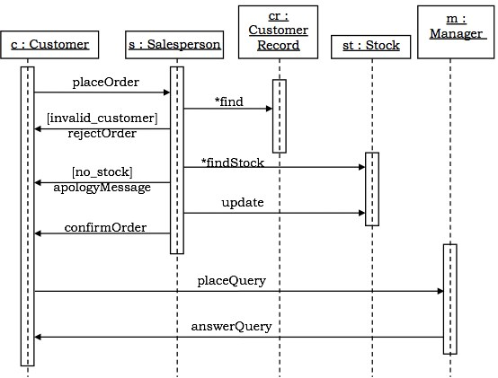
Fig 6: notation of generalizationEssential tips for diagram of the use case Here are some valuable tips to be taken into consideration when drawing a case diagram for use: ● It is important to express a clear and full use case diagram.● Among the different interactions, a use case diagram should represent the most important interaction.● The use case diagram should represent at least one module of a framework.● If the case diagram for use is broad and more complex, it should be more generalized. Q4) What do you mean by interaction diagram ?A4) Interaction Diagram Diagrams of interaction represent objects' experiences and their relationships. The messages exchanged between them often involve them. There are two types of diagrams of interaction: ● Sequence Diagrams● Collaboration Diagrams For modelling, interaction diagrams are used − ● By time ordering, using sequence diagrams, the control flow.● Organization's control flow uses teamwork diagrams. Sequence Diagrams Sequence diagrams are interaction diagrams which demonstrate the time-based ordering of messages. Notations - The two-dimensional maps are in the form of these diagrams. On the x axis, the objects that start the interaction are put. In order to maximise the time from top to bottom, the messages that these objects send and receive are put along the y-axis.
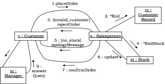
Fig 7: example of sequence diagrams Collaboration Diagram Collaboration diagrams are diagrams of interaction that explain the nature of the messages sent and received by objects. Notations-The artefacts that participate in the interaction are shown using vertices in these diagrams. To send and receive messages, the links that bind the objects are used.
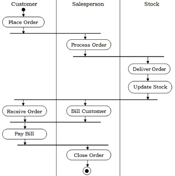
Fig 8: example of collaboration diagram Q5) Describe activity diagram?A5) Activity Diagram In UML, rather than the implementation, the activity diagram is used to show the flow of control within the system. It models operations that are concurrent and sequential. The diagram of the activity helps to imagine the workflow from one activity to another. It stressed the state of flow and the order in which it happens. The flow can be sequential, branched, or concurrent, and the operation diagram has come up with a fork, join, etc. to deal with all kinds of flows. It is often referred to as a flowchart directed towards objects. It covers activities consisting of a series of acts or behaviors that are used to model the behavioral diagram. The flow of events that are continuous non-atomic operations in a state machine is seen in an activity diagram. Activities result in atomic operations, which are actions.
Fig 9: example of activity diagram Diagrams of operation consist of − ● Activity states and action states● Transitions● Objects For modelling operation diagrams are used −● Workflows, which communicate with the system, as viewed by actors.● Information of flowcharted operations or computations.Q6) Explain events and signals?A6) Events and Signals Signals, calls, the passing of time or a change of state can involve events. Each thing that occurs is modelled as an event in UML. An event is the concept of a significant occurrence in time and space that has a venue. Asynchronous events are a signal, a time passage and a shift in state. Generally, calls are synchronous occurrences, reflecting an operation's invocation. UML enables us, as shown below, to graphically depict events. Signals can be interpreted as classes that are stereotyped and other events are represented as transition-related messages that trigger an entity to shift from one state to another.
Fig 10: graphical representation of events Types of events Events may be internal or external. External events are events carried out between the system and its actors. For starters, pressing a button or inserting a card are external events in an ATM system. Internal events are those that move through objects that exist within the device. For instance, an object-generated overflow exception is an internal occurrence. We can model four types of events in UML, i.e.● Signals● Calls● passing of time ● change in state. Signal A signal is a named object which is transmitted by one object asynchronously and then received by another. Exceptions are the popular signal examples. A signal can be transmitted in an interaction as the behavior of a state in a state machine or as a message. The output of an operation can also send signals
Fig 11: example of signals In UML, we model the relationship between an operation and events using a stereotyped "send" dependence, which means that a specific signal is sent by an operation. Calls EventsA call event represents an operation's dispatch from one object to another. In a state machine, a call event may cause a change of state. In general, a call case is a synchronous one. This means that the sender object must wait for the receiver object that receives the call event to receive an acknowledgment.
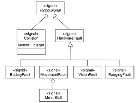
Fig 12: call events Time and Change Events A temporal occurrence illustrates the passing of time. We model the time event in UML using the keyword "after" followed by an expression that evaluates a time frame. An event of change is an event that reflects a change in state or the fulfilment of a certain condition. In UML, the change event is modelled with a "when" keyword followed by a Boolean statement. Sending and Receiving Events A call event or signal may receive any instance of a class. If this is a synchronous call case, the sender and the receiver are in a locked state. If this is a signal, then the sender is free to carry out his operations on the receiver without any worry. In UML, call events are modelled as object class operations and the signals that an object can receive are stored in an additional class component. Modeling a signal family ofTo model a signal family, ● Consider all the signals that can be replied to by a group of objects.● Arrange these signals using the generalization - specialization relationship in a hierarchy.● Look out for polymorphism in the active objects' state machine. Change the hierarchy when polymorphism is detected, by adding intermediate abstract signals.
Fig 13: family of signalsQ7) Define state machine?A7) State MachineA state machine is a behavior that, along with its reactions to certain events, describes the sequences of states that an entity undergoes over its lifetime in response to events. During the existence of an object, the state of an object is a condition or circumstance during which it meets some condition, performs some operation or waits for some event. The State Machine can be visualized in two ways: 1) by concentrating on the flow of control from one activity to another (using activity diagrams) or by focusing on the flow of control from one activity to another.2) by concentrating on the state of objects and on the transitions between those states,
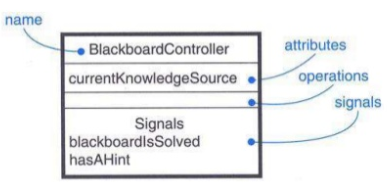
Fig 14: state machine Q8) Explain process and thread?A8) Process and ThreadsA method is a heavyweight flow that can be executed with other processes simultaneously. A thread is a lightweight flow that within the same process may run simultaneously with other threads. An active object is an object that owns a process or thread and is capable of initiating operation control. A class whose instances are active objects is an active class. Graphically, a rectangle with thick lines is rendered as an active class. Threads and processes are made as active groups that are stereotyped.
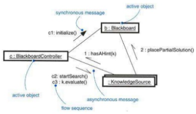
Fig 15: active class Flow of control There are two control flows that are both concurrent and simultaneous. There is a single flow of control within a sequential scheme. In other words, one thing, and only one thing, will take place at a time. Control is rooted at the beginning of the programme as a sequential programme begins, and operations are dispatched one after another. A sequential programme can process only one event at a time, queuing or discarding any concurrent external events, even though there are concurrent things occurring among the actors outside the system. There are many simultaneous control flows in a concurrent system, i.e., more than one thing may take place at a time, each rooted at the head of an independent loop or a thread. Logically, if you take a snapshot of a parallel machine as it is running, you can see multiple execution locations. You use an active class in the UML to describe a method or thread that is the origin of an individual control flow and that is simultaneous with all control peer flows. Classes and Event Active classes are merely classes that reflect an independent control source. As with all other classes, active classes share the same properties. The associated control flow is initiated when an active object is created; the associated control flow is terminated when the active object is destroyed. As with all other classes, active classes share the same properties. There may be cases of active classes. Active classes can have operations and attributes. In dependence, generalization, and association (including aggregation) relationships, active classes can participate. Any of the UML's extensibility mechanisms, including stereotypes, tagged values and restrictions, can be used by active classes. The realisation of interfaces could be active classes. Active classes can be realised by partnerships, and state machines can be used to define the actions of an active class. Standard Element For active classes, all of UML's extensibility mechanisms apply. You will most frequently use tagged values to expand the active class properties, such as defining the active class scheduling policy. Two typical stereotypes that apply to active classes are specified in the UML Specifies a heavyweight flow that can be done with other processes simultaneously. ThreadSpecifies a lightweight flow that can be executed within the same process simultaneously with other threads. There's a lightweight thread. The operating system itself might be aware of that. It is most frequently hidden within a heavier-weight process and runs within the enclosing process's address space. A thread, for example, in Java, is a child of the Thread class. Communication When objects collaborate with each other, by transmitting messages from one to the other, they interact. There are four potential combinations of interaction in a system of both active and passive objects that you must remember. Second, from one passive object to another, a message can be passed on. Assuming that only one control flow passes through these objects at a time, such an interaction is nothing more than an operation's basic invocation. Second, from one active object to another, a message can be transmitted. You have interprocess contact when that happens, and there are two possible communications types. Third, from an active object to a passive object, a message may be passed on. If more than one active object transfers its flow of influence through one passive object at a time, a problem occurs. In that case, Fourth, from a passive entity to an active one, a message may be transmitted. This may sound illegal at first glance, but if you note that every control flow is embedded in some active object, you will realise that a passive object that passes a message to an active object has the same semantics as an active object that passes a message to an active object.
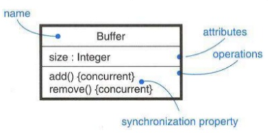
Fig 16: communication Synchronization Synchronization implies organizing the movement of object controls so that mutual exclusion is maintained. These objects are viewed as a crucial field in object-oriented systems. To control synchronization, there are three approaches: 1. Sequential: outside the object, callers must coordinate so that only one flow is in the object at a time.2. Guarded-Multiple control flow is sequential zed with the aid of protected operations of the object. It becomes sequential, in effect.3. Concurrent: by considering each operation as atomic, multiple control flow is assured. With the help of constraints, synchronization is performed in the operations of active groups.
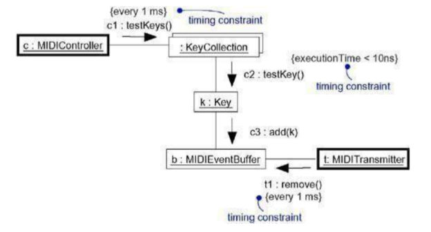
Fig 17: synchronization Process views A system's process view covers the threads and processes that shape the mechanisms of concurrency and synchronization of the system. This view mainly addresses the system's performance, scalability, and throughput. Q9) What do you mean by time and space?A9) Time and SpaceFor the time at which an event takes place, a timing mark is a denotation. Graphically, as an expression from the name given to the message, a timing mark is formed. An expression of time is an expression which evaluates time to an absolute or relative value. A restriction on timing is a semantic assertion about the relative or absolute time value. Graphically, as with any constraint, a timing constraint is made, that is, a string enclosed by brackets and generally linked by a dependency relationship to an element. Location is a component placement on a node. Graphically, the position is made as a tagged value, that is, a string enclosed by brackets and placed below the name of an entity, or as a nesting value.Node-inside components. Time Real time systems are time-critical systems, by their own name. Events may occur at normal or unusual times; event response must occur at predictable absolute times or at predictable times relative to the event. In itself. Passing messages reflects the dynamic aspect of any system, so you can assign a name to each message in an interaction to be used as a timing mark when you model the time-critical nature of a system with UML. Messages are normally not assigned names in an interaction. If there is an ambiguity in the specified message, use the explicit message name in the timing mark to specify the message you want to specify in the time expression. In an interaction, a timing mark is nothing more than a phrase created from a message's name. You may refer to any of the three functions of that message, namely startTime, stopTime, and executionTime, provided the name of the message. You can then use these functions to define arbitrarily complicated time expressions, perhaps even using constant or variable weights or offsets (as long as those variables can be bound at execution time).
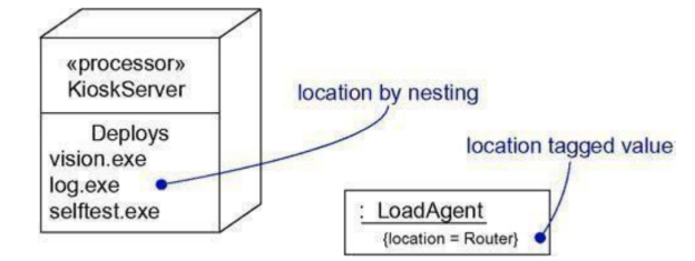
Fig 18: timing Location Through their essence, distributed systems encompass components that are physically dispersed between a system's nodes. Components are fixed in place for many systems at the time they are loaded onto the system; components may move from node to node in other systems.In the UML, you model a system's deployment view by using deployment diagrams describing the topology of the processors and devices operating on your system. Components such as databases, executables, and tablesOn these nodes, they live. Each node instance will own instances of some components, and each component instance will be owned by exactly one node instance.
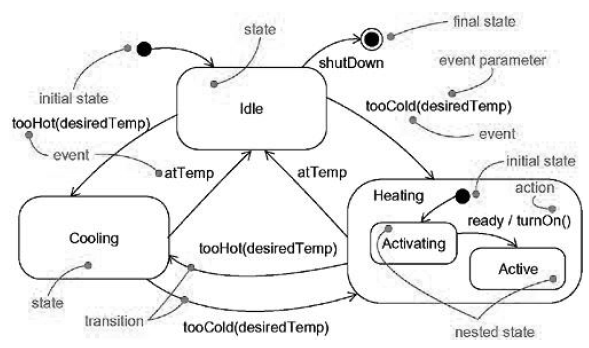
Fig 19: location Q10) Explain state chart diagram?A10) State chart Diagram A state-chart diagram displays a state machine describing an object's control flow from one state to another. The sequences of states that an entity undergoes due to events and their reactions to events are represented by a state machine. State-Chart Diagrams consist of − ● States: Simple or Composite● Transitions between states● Events causing transitions● Actions due to the events To model objects which are reactive in nature, state-chart diagrams are used.
Fig 20: example of state chart diagram
|
|
|
|
|
|
|
|
|
|
|
|
|
|
|
|
|
|
|
|
|
0 matching results found
