UNIT 1
1.Briefly explain Drawing instruments and their uses?
Tracing paper
Tracing papers are thin papers, natural or transparent, on which drawings are traced, in pencil or ink, and from which blueprints or similar contact prints can be made. In most drafting rooms original drawings are penciled on tracing papers, and blueprints are made directly from these drawings, a practice increasingly successful because of improvements both in papers and in printing.
Thumbtacks
The best thumbtacks are made with thin heads and steel points screwed into them. Cheaper ones are made by stamping. Use tacks with tapering pins of small diameter and avoid flat-headed (often colored) map pins, as the heads are too thick and the pins rather large.
Pencils
The basic instrument is the graphite lead pencil, made in various hardness’s. Each manufacturer has special methods of processing design to make the lead strong and yet give a smooth clear line.
In the left there is an ordinary pencil, with the lead set in wood and the other is a semi-automatic pencil with thinner leads. Both are fine but have the disadvantage that in use, the wood must be cut away to expose the lead (a time-consuming job), and the pencil becomes shorter and shorter until the last portion of it is to be discarded. Where as semi automatic pencils, with a chuck to clamp and hold the lead, are more convenient, has a plastic handle and changeable tip (for indicating the grade of lead).
Drawing pencils are graded by numbers and letters from 6B which is very soft and black, to 5B, 4B, 3B, 2B, B, and HB to F, the medium grade; then H, 2H, 3H, 4H, 5H, 6H, 7H, and 8H to 9H, the hardest. The soft (B) grades are used primarily for sketching and rendered drawings and the hard (H) grades for instrument drawings.
Pencil Pointer
After the wood of the ordinary pencil is cut away with a pocketknife or mechanical sharpener, the lead must be formed to a long, conic point.
A pencil pointer is a tool for sharpening a pencil’s writing point by shaving away its worn surface.
Erasers
The Ruby pencil eraser, large size with beveled ends, is the standard. This eraser not only removes pencil lines effectively but is better for ink, as it removes ink without seriously damaging the surface of paper or cloth.
Art gum or a soft-rubber eraser is useful for cleaning paper and cloth of finger marks and smears that spoil the appearance of the completed drawing.
Penholders and Pens
The penholder should have a grip of medium size, small enough to enter the mouth of a drawing-inkbottle easily yet not as small as to cramp the fingers while in use. A size slightly larger than the diameter of a pencil is good.
Triangles
Triangles, are made of transparent hard or other plastic material. Through internal strains they sometimes lose their accuracy. Triangles should be kept flat to prevent warping. For ordinary work, a 6- or 8-in. 45° and a 10-in. 30-60° are good sizes.
The T squares
The fixed-head T square, is used for all ordinary work. It should be of hardwood, and the blade should be perfectly straight. The transparent-edged blade is much the best. A draftsman will have several fixed-head squares of different lengths and will find an adjustable-head square of occasional use.
Curves:
Curve rulers, called "irregular curves" or "French curves," are used to draw curved lines other than circular arcs. The patterns for these curves are laid out in parts of ellipse and spirals or other mathematical curves in various combinations. For the student, one ellipse curve of the general shape or one spiral, either a logarithmic spiral is a useful small curve.
The Case Instruments:
We have so far, except for curves considered only the instruments needed for drawing straight lines. A major portion of any drawing is likely to be circles and circle arcs, and the so called “case” instruments are used for these.
Divider
It is used for laying off or transferring measurements.
Next is the large compass with lengthening bar and pen attachment. The three “bow” instruments are for smaller work. They are almost always made without the conversion feature.
The ruling pen is used for inking straight lines.
Protractor is used to measure angles up to 180°.
2. Explain Layout of drawing sheets?
Engineering drawings are prepared on standard size drawing sheets. The correct shape and size of the object can be visualized from the understanding of not only its views but also from the various types of lines used, dimensions, notes, scale etc. For uniformity, the drawings must be drawn as per certain standard practice.
Drawing sheet layout
The layout of a drawing sheet used on the shop floor is shown in Fig.1. The layout suggested to students is shown in Fig.2.
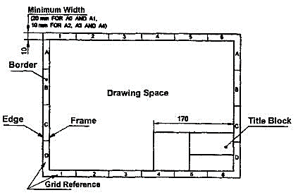
Figure 1 General features of a drawing sheet
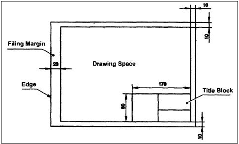
Figure 2 Layout of sheet for a class work
3. Explain the Sizes of Drawing Sheets?
The standard drawing sheet sizes are arrived at on the basic Principal of x: y = 1: and xy = 1 where x and yare the sides of the sheet. For example, A0, having a surface area of 1 Sq. m; x = 841 mm and y = 1189 mm. The successive sizes are obtained by either by halving along the length or doubling the width, the area being in the ratio 1: 2. Designation of sizes is given in Fig.3 and their sizes are given in Table 1. For class work use of A2 size drawing sheet is preferred.
Table 1
Designation | Dimension, mm (Trimmed size) |
A0 | 841 × 1189 |
A1 | 594 × 841 |
A2 | 420 × 594 |
A3 | 297 × 420 |
A4 | 210 × 297 |
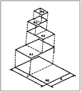
Figure 3
4. Explain Title block of the drawing sheet?
The title block should lie within the drawing space at the bottom right hand comer of the sheet. The title block can have a maximum length of 170 mm providing the following information.
1. Title of the drawing.
2. Drawing number.
3. Scale.
4. Symbol denoting the method of projection.
5. Name of the firm, and
6. Initials of staff who have designed, checked and approved.
The title block used on shop floor and one suggested for student’s class work are shown inFig.4& Fig. 5.

Figure 4 Shop floor drawing sheet layout
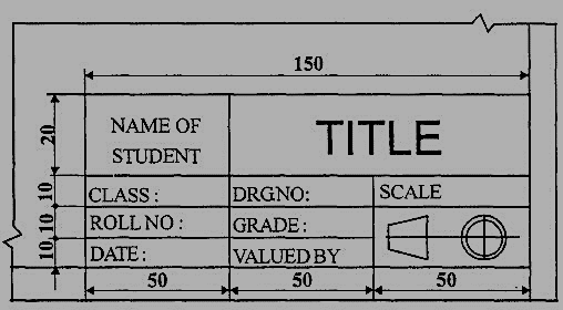
Figure 5 Students class work
5. What are the Different types of lines used in drawing practice?
Just as in English textbook the correct words are used for making correct sentences; in Engineering Graphics, the details of various objects are drawn by different types of lines. Each line has a definite meaning and sense to convey.
IS 10714 (Pint 20): 2001 (General principles of presentation on technical drawings) and SP 46:2003specify the following types oflines and their applications:
1. Visible Outlines, Visible Edges: (Continuous wide lines) the lines drawn to represent the visible outlines/ visible edges / surface boundary lines of objects should be outstanding in appearance.
2. Dimension Lines: (Continuous narrow Lines) Dimension Lines are drawn to mark dimension.
3. Extension Lines: (Continuous narrow Lines) There are extended slightly beyond the respective dimension lines.
4. Construction Lines: (Continuous narrow Lines) Construction Lines are drawn for constructing drawings and should not be erased after completion of the drawing.
5. Hatching / Section Lines: (Continuous Narrow Lines)
Hatching Lines are drawn for the sectioned portion of an object. These are drawn inclined at an angle of 45° to the axis or to the main outline of the section.
6. Guide Lines: (Continuous Narrow Lines)
Guide Lines are drawn for lettering and should not be erased after lettering.
7. Break Lines: (Continuous Narrow Freehand Lines)
Wavy continuous narrow line drawn freehand is used to represent break of an object.
8. Break Lines: (Continuous Narrow Lines with Zigzags)
Straight continuous arrow line with zigzags is used to represent break of an object.
9. Dashed Narrow Lines: (Dashed Narrow Lines)
Hidden edges / Hidden outlines of objects are shown by dashed lines of short dashes of equal lengths of about 3 mm, spaced at equal distances of about 1 mm. The points of intersection of these lines with the outlines / another hidden line should be clearly shown.
10. Center Lines: (Long-Dashed Dotted Narrow Lines)
Center Lines are drawn at the center of the drawings symmetrical about an axis or both the axes. These are extended by a short distance beyond the outline of the drawing.
11. Cutting Plane Lines:
Cutting Plane Line is drawn to show the location of a cutting plane. It is long-dashed dotted narrow line, made wide at the ends, bends and change of direction. The direction of viewing is shown by means of arrows resting on the cutting plane line.
12. Border Lines
Border Lines are continuous wide lines of minimum thickness 0.7 mm.
Line widths:
Line width means line thickness
Choose line widths according to the size of the drawing from the following range: 0.13, 0.18, 0.25, 0.35, 0.5, 0.7 and 1 mm.
Precedence of Lines
1. When a Visible Line coincides with a Hidden Line or Center Line, draw the Visible Line. Also, extend the Center Line beyond the outlines of the view.
2. When a Hidden Line coincides with a Center Line, draw the Hidden Line.
3. When a Visible Line coincides with a Cutting Plane, draw the Visible Line.
4. When a Center line coincides with a Cutting Plane, draw the Center Line and show the
Cutting Plane line outside the outlines of the view at the ends of the Center Line by thick dashes.
6. Explain Dimensioning system as per BIS (Theoretical treatment only)?
Drawing of a component, in addition to providing complete shape description, must also furnish information regarding the size description. These are provided through the distances between the surfaces, location of holes, nature of surface finish, type of material, etc. The expression of these features on a drawing, using lines, symbols, figures and notes is called dimensioning.
Principles of Dimensioning
Some of the basic principles of dimensioning are given below.
1. All dimensional information necessary to describe a component clearly and completely shall be written directly on a drawing.
2. Each feature shall be dimensioned once only on a drawing, i.e., dimension marked in one view need not be repeated in another view.
3. Dimension should be placed on the view where the shape is best
4. As far as possible, dimensions should be expressed in one unit only preferably in millimeters, without showing the unit symbol (mm).
5. As far as possible dimensions should be placed outside the view
6. Dimensions should be taken from visible outlines rather than from hidden lines
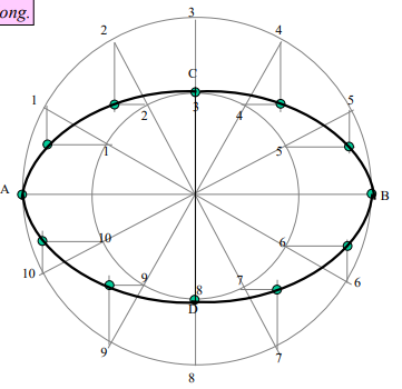
7. Draw ellipse by concentric circle method. Take major axis 100 mm and minor axis 70 mm long.
Steps:
1. Draw both axes as perpendicular bisectors of each other & name their ends as shown.
2. Taking their intersecting point as a center, draw two concentric circles considering both as respective diameters.
3. Divide both circles in 12 equal parts & name as shown.
4. From all points of outer circle draw vertical lines downwards and upwards respectively. 5.From all points of inner circle draw horizontal lines to intersect those vertical lines.
6. Mark all intersecting points properly as those are the points on ellipse.
7. Join all these points along with the ends of both axes in smooth possible curve. It is required ellipse.
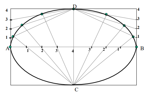
8. Draw ellipse by Rectangle method. Take major axis 100 mm and minor axis 70 mm long.
Steps:
1 Draw a rectangle taking major and minor axes as sides.
2. In this rectangle draw both axes as perpendicular bisectors of each other..
3. For construction, select upper left part of rectangle. Divide vertical small side and horizontal long side into same number of equal parts.( here divided in four parts)
4. Name those as shown..
5. Now join all vertical points 1,2,3,4, to the upper end of minor axis. And all horizontal points i.e.1,2,3,4 to the lower end of minor axis.
6. Then extend C-1 line upto D-1 and mark that point. Similarly extend C-2, C-3, C-4 lines up to D-2, D-3, & D-4 lines.
7. Mark all these points properly and join all along with ends A and D in smooth possible curve. Do similar construction in right side part.along with lower half of the rectangle.
8. Join all points in smooth curve. It is required ellipse.
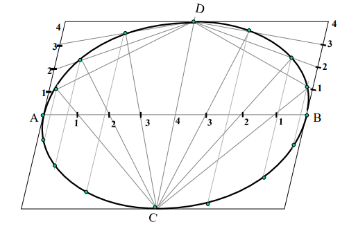
9. Draw ellipse by Oblong method. Draw a parallelogram of 100 mm and 70 mm long sides with included angle of 750.Inscribe Ellipse in it.
(STEPS ARE SIMILAR TO THE PREVIOUS CASE (RECTANGLE METHOD) ONLY IN PLACE OF RECTANGLE, HERE IS A PARALLELOGRAM)
10. MAJOR AXIS AB & MINOR AXIS CD ARE 100 AMD 70MM LONG RESPECTIVELY .DRAW ELLIPSE BY ARCS OF CIRLES METHOD.
STEPS:
1.Draw both axes as usual. Name the ends & intersecting point
2.Taking AO distance I.e. half major axis, from C, mark F1 & F2 On AB . ( focus 1 and 2.)
3.On line F1 - O taking any distance, mark points 1,2,3, & 4
4.Taking F1 center, with distance A-1 draw an arc above AB and taking F2 center, withB-1 distance cut this arc. Name the point p1
5.Repeat this step with same centers but taking now A-2 & B-2 distances for drawing arcs. Name the point p2
6.Similarly get all other P points. With same steps positions of P can be located below AB.
7.Join all points by smooth curve to get an ellipse/

11. Draw an isosceles triangle of 100 mm long base and 110 mm long altitude. Inscribe a parabola in it by method of tangents.
Solution Steps:
1. Construct triangle as per the given dimensions.
2. Divide it’s both sides in to same no.of equal parts.
3. Name the parts in ascending and descending manner, as shown.
4. Join 1-1, 2-2,3-3 and so on.
5. Draw the curve as shown i.e.tangent to all these lines. The above all lines being tangents to the curve, it is called method of tangents.
