UNIT 2
1. What is the magnetomotive force (mmf) of a wire with 6 turns carrying 4 amperes of current?
Ans. Current flowing through the wire i=4 A
Number of turns N=6
Thus magneto motive force =Ni=6×4=24 At
2. Determine the reluctance (in Amp-turns/Wb) of a coil, when the flux through the coil is 20 Wb and the produced MMF is 40 Amp-turns.
Ans. The reluctance of any part of a magnetic circuit may be defined as the ratio of the drop in magnetomotive force to the flux produced in that part of the circuit. It is measured in ampere-turns/Weber and is denoted by S.
Reluctance = m.m.f ⁄ flux
Reluctance = 40 ⁄ 20
Reluctance = 2 Amp-turns/Wb
3. Determine the value of produced MMF (in Amp-turns) in a coil if the coil has 100 turns carrying a current of 0.1 A.
Ans. Magnetomotive force (MMF) is defined as the force that drives magnetic flux throng the magnetic circuit. In all practical magnetic circuits, this is provided using a current-carrying winding (coil) and is the product of the current and the number of turns in the winding. Its SI unit of measurement is the ampere.
m.m.f Fm = N.I Ampere-turn
Where N is the number of conductors (or turns) and I is the current in amperes. The unit of MMF is sometimes expressed as ‘ampere-turns’. However, since ‘turns’ have no dimensions, the Sl unit of MMF is the amp.
Given,
Number of turns N = 100 turns
Current I = 0.1 A
Fm = 100 × 0.1
Fm = 10 Ampere-turns
4. Determine the intensity of the magnetization (in A/m) of a magnet when it has a pole strength of 40 A-m and a pole area of 10 sq.m
Ans. The intensity of magnetization ( I ): The intensity of magnetization of a magnetized specimen is a measure of its ma~netisation. It is defined as the magnetic moment per unit volume, the specimen is so small that its magnetization can be supposed to be uniform. It is the degree to which a substance is magnetized when placed in a magnetic field It is denoted by I.
I = Magnetic Movement ⁄ Volume
If the specimen is of the uniform cross-sectional area (a), magnetic length 2L, and pole strength m,
Then M = m × 2L and V = a × 2L.
Hence I = (m × 2L) ⁄ (a × 2L) = m ⁄ a
Thus, in the case of specimen Uniform cross-section, the intensity of magnetization is given by pole strength per unit face area.
I = Pole Strenght ⁄ Pole Area
Pole strength = 40 A-m
Pole area = 10 m2
Intensity = 40 ⁄ 10 = 4 A/m
5. What will be the magnitude of induced EMF (in V) in a coil that has 250 square loops, each of the sides 4 cm and placed normal to a magnetic field? The magnetic field increases at the rate of 5 Weber per sq. Meter.
Ans. If N is the number of turns in the coil, f is the frequency of rotation, A is the area of coil and B is the magnetic induction then induced emf is given by
e = −dφ/dt
Flux linkage through the coil is
φ = NBA cosωt
Or
e = −dNBA cosωt ⁄ dφ
So According to Faraday’s Law whenever there is a change in the magnetic flux linked with a coil, a] instantaneous emf is induced in the coil. The magnitude of the emf induced in the coil is proportional to the rate of variation of the magnetic flux linked with the coil:
e = −dNBA cosωt ⁄ dφ
Number of turns N = 250
Area A = 0.042
The rate of change of flux dφ ⁄ dt = 5
∴ The magnitude of the induced E.M.F is
E = 250 × 0.042 × 5
E = 2V
6. Calculate the value of the flux leakage coefficient, if φg is the air gap flux and φa is the flux in the iron core.
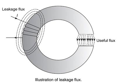
Ans. The flux which does not follow the desired path of magnetic material is called leakage flux. Generally, it is not possible to confine the entire flux to the iron path only, unlike an electric current that can be confined to a wire by providing proper insulation. In any magnetic circuit, it is impossible to avoid magnetic leakage since there is no magnetic insulator available in practice. For example, the air is a good insulator of electricity, though, it conducts magnetic flux. The flux in the air gap is known as a useful flux because it can be utilized for practical purposes.
The figure shows an iron ring wound with a coil and having a narrow air gap. The total flux produced by the coil does not pass through the air gap as some of it leaks through the air surrounding the ring. These flux lines are called leakage flux.
Therefore the part of the magnetic flux that has its path within the magnetic circuit is known as the useful flux or main flux and that taking other paths is called leakage flux. This phenomenon of wastage of some flux is called magnetic leakage. Sum of the two parts is called the total flux produced.
The ratio of the total flux produced by the magnet to the main flux is called leakage coefficient or leakage factor.
Or
The ratio of total flux (flux in the iron path) to the useful flux (flux in the air gap) is known as leakage factor (λ).
Mathematically, leakage factor can be written as
Leakage factor λ = φT ⁄ φm = Total useful flux ⁄ Main flux = (φL + φm) ⁄ φm
Where
φL = Leakage flux
φm = Main flux
φT = Total flux
Or
Leakage factor λ = (Flux in the Iron Path) / (Flux in the air Gap)
λ = φa ⁄ φg
7. A conductor of length 0.5 m is situated at the right angle to a uniform magnetic field of flux density 3 Wb/sq.m. The conductor is moving with a velocity of 40m/s. Calculate the emf induced (in V) in the conductor.
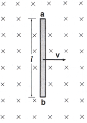
Ans. The emf induced in a straight conductor of length l moving with velocity v perpendicular to a magnetic field B is
E = Blvsinθ
Where
E is the generated voltage =?
B is the magnetic flux density = 3 Wb/m2
l is the length of a conductor in the magnetic field = 0.5 m
v is the velocity of the conductor perpendicular to the magnetic lines = 40m/s
The value of sinθ is maximum at 90 degrees i.e When the coil is perpendicular to the field axis. i.e
E = Blv
E = 3 × 0.5 × 40 = 60 V
E = 60 Volts
8. A flux of 3mWb passes through a strip of length and breadth 20 cm and 30 cm respectively. It is placed at an angle of 30 degrees to the direction of uniforms magnetic field. What is the magnetic flux density (in T)?
Ans. Accordingly, the magnetic flux φ passing through a surface of area A with a normal at an angle θ to a magnetic field of flux density B is given by:
φ = B.A.Cosθ
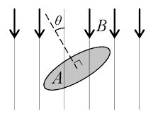
Where
φ = Magnetic flux = 3mWb = 3 × 10⁻³ Wb
A = Area = (Length × Breadth) = (20 × 30) = 600 cm2 = 600 × 10−4 m2
θ = Angle to the magnetic field = 30°
B = Magnetic flux density =?
3 × 10−3 = B × 600 × 10−4 × Cos30°
B = (3 × 10⁻³ ) ⁄ (600 × 10−4) × 0.866
B = 0.0577 Tesla or Wb/m2
9. A magnetic circuit of reluctance 4000 A-turns/Wb is wounded by a wire of 500 turns. Determine the average E.M.F induced (in V) in the coil, if the current of 3 A is flowing in the coil is reversed in 15s.
Ans. The Relation Between the Inductance and the Reluctance is
L = N2/ℜ
Where
N = Number of turns
ℜ = Reluctance of the coil
L = (500)2 ⁄ 4000
L = 62.5 H
Hence the Average Induced EMF will be
E = L.Δi ⁄ t
Where
L is the inductance of the coil = 62.5 H
t = time = 15 sec
Δi is the change in current in A
Now change in current
Δi = 3 − (−3) = 6A (since the current is reversed)
Putting all the value in the equation
E = (62.5 × 6) ⁄ 15
E = 25 Volt
10. Determine the flux (in Wb) through a coil when the reluctance of the coil is 5 Amp-turns/Wb and the produced MMF is 60 Amp-turns.
Ans. Similar to the resistance characteristic in electricity, we have reluctance in magnetism which is the property of the substance that opposes the magnetic flux through it.
The reluctance of any part of a magnetic circuit may be defined as the ratio of the drop in magnetomotive force to the flux produced in that part of the circuit. It is measured in ampere-turns/Weber and is denoted by S.
Reluctance = m.m.f ⁄ flux
5 = 60 ⁄ Flux
Flux = 12 Wb
UNIT 2
1. What is the magnetomotive force (mmf) of a wire with 6 turns carrying 4 amperes of current?
Ans. Current flowing through the wire i=4 A
Number of turns N=6
Thus magneto motive force =Ni=6×4=24 At
2. Determine the reluctance (in Amp-turns/Wb) of a coil, when the flux through the coil is 20 Wb and the produced MMF is 40 Amp-turns.
Ans. The reluctance of any part of a magnetic circuit may be defined as the ratio of the drop in magnetomotive force to the flux produced in that part of the circuit. It is measured in ampere-turns/Weber and is denoted by S.
Reluctance = m.m.f ⁄ flux
Reluctance = 40 ⁄ 20
Reluctance = 2 Amp-turns/Wb
3. Determine the value of produced MMF (in Amp-turns) in a coil if the coil has 100 turns carrying a current of 0.1 A.
Ans. Magnetomotive force (MMF) is defined as the force that drives magnetic flux throng the magnetic circuit. In all practical magnetic circuits, this is provided using a current-carrying winding (coil) and is the product of the current and the number of turns in the winding. Its SI unit of measurement is the ampere.
m.m.f Fm = N.I Ampere-turn
Where N is the number of conductors (or turns) and I is the current in amperes. The unit of MMF is sometimes expressed as ‘ampere-turns’. However, since ‘turns’ have no dimensions, the Sl unit of MMF is the amp.
Given,
Number of turns N = 100 turns
Current I = 0.1 A
Fm = 100 × 0.1
Fm = 10 Ampere-turns
4. Determine the intensity of the magnetization (in A/m) of a magnet when it has a pole strength of 40 A-m and a pole area of 10 sq.m
Ans. The intensity of magnetization ( I ): The intensity of magnetization of a magnetized specimen is a measure of its ma~netisation. It is defined as the magnetic moment per unit volume, the specimen is so small that its magnetization can be supposed to be uniform. It is the degree to which a substance is magnetized when placed in a magnetic field It is denoted by I.
I = Magnetic Movement ⁄ Volume
If the specimen is of the uniform cross-sectional area (a), magnetic length 2L, and pole strength m,
Then M = m × 2L and V = a × 2L.
Hence I = (m × 2L) ⁄ (a × 2L) = m ⁄ a
Thus, in the case of specimen Uniform cross-section, the intensity of magnetization is given by pole strength per unit face area.
I = Pole Strenght ⁄ Pole Area
Pole strength = 40 A-m
Pole area = 10 m2
Intensity = 40 ⁄ 10 = 4 A/m
5. What will be the magnitude of induced EMF (in V) in a coil that has 250 square loops, each of the sides 4 cm and placed normal to a magnetic field? The magnetic field increases at the rate of 5 Weber per sq. Meter.
Ans. If N is the number of turns in the coil, f is the frequency of rotation, A is the area of coil and B is the magnetic induction then induced emf is given by
e = −dφ/dt
Flux linkage through the coil is
φ = NBA cosωt
Or
e = −dNBA cosωt ⁄ dφ
So According to Faraday’s Law whenever there is a change in the magnetic flux linked with a coil, a] instantaneous emf is induced in the coil. The magnitude of the emf induced in the coil is proportional to the rate of variation of the magnetic flux linked with the coil:
e = −dNBA cosωt ⁄ dφ
Number of turns N = 250
Area A = 0.042
The rate of change of flux dφ ⁄ dt = 5
∴ The magnitude of the induced E.M.F is
E = 250 × 0.042 × 5
E = 2V
6. Calculate the value of the flux leakage coefficient, if φg is the air gap flux and φa is the flux in the iron core.
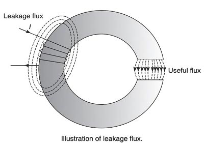
Ans. The flux which does not follow the desired path of magnetic material is called leakage flux. Generally, it is not possible to confine the entire flux to the iron path only, unlike an electric current that can be confined to a wire by providing proper insulation. In any magnetic circuit, it is impossible to avoid magnetic leakage since there is no magnetic insulator available in practice. For example, the air is a good insulator of electricity, though, it conducts magnetic flux. The flux in the air gap is known as a useful flux because it can be utilized for practical purposes.
The figure shows an iron ring wound with a coil and having a narrow air gap. The total flux produced by the coil does not pass through the air gap as some of it leaks through the air surrounding the ring. These flux lines are called leakage flux.
Therefore the part of the magnetic flux that has its path within the magnetic circuit is known as the useful flux or main flux and that taking other paths is called leakage flux. This phenomenon of wastage of some flux is called magnetic leakage. Sum of the two parts is called the total flux produced.
The ratio of the total flux produced by the magnet to the main flux is called leakage coefficient or leakage factor.
Or
The ratio of total flux (flux in the iron path) to the useful flux (flux in the air gap) is known as leakage factor (λ).
Mathematically, leakage factor can be written as
Leakage factor λ = φT ⁄ φm = Total useful flux ⁄ Main flux = (φL + φm) ⁄ φm
Where
φL = Leakage flux
φm = Main flux
φT = Total flux
Or
Leakage factor λ = (Flux in the Iron Path) / (Flux in the air Gap)
λ = φa ⁄ φg
7. A conductor of length 0.5 m is situated at the right angle to a uniform magnetic field of flux density 3 Wb/sq.m. The conductor is moving with a velocity of 40m/s. Calculate the emf induced (in V) in the conductor.
Ans. The emf induced in a straight conductor of length l moving with velocity v perpendicular to a magnetic field B is
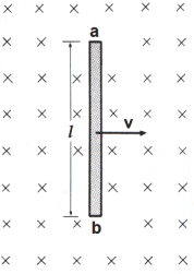
E = Blvsinθ
Where
E is the generated voltage =?
B is the magnetic flux density = 3 Wb/m2
l is the length of a conductor in the magnetic field = 0.5 m
v is the velocity of the conductor perpendicular to the magnetic lines = 40m/s
The value of sinθ is maximum at 90 degrees i.e When the coil is perpendicular to the field axis. i.e
E = Blv
E = 3 × 0.5 × 40 = 60 V
E = 60 Volts
8. A flux of 3mWb passes through a strip of length and breadth 20 cm and 30 cm respectively. It is placed at an angle of 30 degrees to the direction of uniforms magnetic field. What is the magnetic flux density (in T)?
Ans. Accordingly, the magnetic flux φ passing through a surface of area A with a normal at an angle θ to a magnetic field of flux density B is given by:
φ = B.A.Cosθ
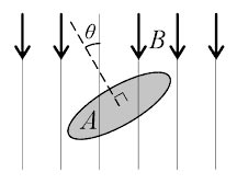
Where
φ = Magnetic flux = 3mWb = 3 × 10⁻³ Wb
A = Area = (Length × Breadth) = (20 × 30) = 600 cm2 = 600 × 10−4 m2
θ = Angle to the magnetic field = 30°
B = Magnetic flux density =?
3 × 10−3 = B × 600 × 10−4 × Cos30°
B = (3 × 10⁻³ ) ⁄ (600 × 10−4) × 0.866
B = 0.0577 Tesla or Wb/m2
9. A magnetic circuit of reluctance 4000 A-turns/Wb is wounded by a wire of 500 turns. Determine the average E.M.F induced (in V) in the coil, if the current of 3 A is flowing in the coil is reversed in 15s.
Ans. The Relation Between the Inductance and the Reluctance is
L = N2/ℜ
Where
N = Number of turns
ℜ = Reluctance of the coil
L = (500)2 ⁄ 4000
L = 62.5 H
Hence the Average Induced EMF will be
E = L.Δi ⁄ t
Where
L is the inductance of the coil = 62.5 H
t = time = 15 sec
Δi is the change in current in A
Now change in current
Δi = 3 − (−3) = 6A (since the current is reversed)
Putting all the value in the equation
E = (62.5 × 6) ⁄ 15
E = 25 Volt
10. Determine the flux (in Wb) through a coil when the reluctance of the coil is 5 Amp-turns/Wb and the produced MMF is 60 Amp-turns.
Ans. Similar to the resistance characteristic in electricity, we have reluctance in magnetism which is the property of the substance that opposes the magnetic flux through it.
The reluctance of any part of a magnetic circuit may be defined as the ratio of the drop in magnetomotive force to the flux produced in that part of the circuit. It is measured in ampere-turns/Weber and is denoted by S.
Reluctance = m.m.f ⁄ flux
5 = 60 ⁄ Flux
Flux = 12 Wb