ECD-II
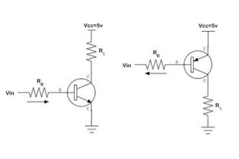
Unit 5Multivibrator Q 1) Explain the working of transistor as a switch?A 1)The purpose of using transistor as a switch is that the current at the base controls the current present at the collector directly. If the current at the base exceeds the minimum cut-off voltage then transistor acts a close switch otherwise it will remain in open switch condition.
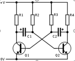
Figure 1. Transistor as SwitchWhen bias is applied to the base of the transistor both the types in bipolar junction transistor are used as switches. The areas at which the operation of the switch is preferred is either it should be completely in the region called saturation or the cut-off operating region.Q2) Explain the transistor switching parameters?A 2)Current gain:In any circuit, the current gain of a transistor is an important parameter. Current gain is usually referred to as a β or hfe. Current is the ratio of the base current to the collector current and a measure of the amplifying ability of the transistor. Collector-Emitter Voltage (VCEO)VCEO is the maximum voltage that the collector-emitter junction of a transistor can handle. For most of the transistors, VCEO is usually 30V or more and measured with the base open circuit. Applying a higher voltage than VCEO can damage your transistor. Emitter-Base Voltage (VEBO)VEBO is the maximum voltage that can be applied across the emitter-base junction. Higher voltage than the VEBO can damage or destroy your transistor. Collector-Base Voltage (VCBO)VCBO is the maximum voltage that can be applied across the collector-base junction, and it is measured with the emitter open circuit. VCBO is usually 50V or more. Collector current (IC)Collector current is the maximum current that can flow through the collector. It is generally defined in milliamps, but for high power transistors, it is defined in amps. Total Power Dissipation (Ptot)It is the total power dissipated by the transistor. Power dissipation varies by a transistor to a transistor. For small transistors, the power rating is on the order of a few hundred milliwatts, but for high power transistors, it is defined in watts. Q 3) Explain the classification of multivibarator?A 3)Multivibrator is an electronic circuit which is used to implement a variety of two state systems such as oscillators, timers, and flip-flops. It is characterized by two amplifying devices transistors, electron tubes or other devices cross coupled by resistors or capacitors.They are classified as:Astable multivibrator Mono stable multivibrator Bistable multivibrator Q 4) Write a short note on Astable Multivibrator?A 4) Astable multivibrator
Figure . Astable Multivibrator Astable is known as free running multivibrator, sometimes called as square wave generator. The circuit has two quasi -stable states that is no stable state. Thus, three is an oscillation between two state, hence no external signals are required to produce change in state. Astable circuits are used to generate square wave for example clock generators in digital system.Q 5) Write a short note on monostable multivibrator?A 5)
Figure . Mono stable multivibratorThe mono stable or one -shot multivibrator generates signal pulse of specified duration to each external trigger.Here only one stable state exists. On the application of each trigger there lies a change to quasi stable state. The circuit remains in the quasi -stable state for a fixed interval of time and then reverts to its original stable state. The internal trigger signal generated produces the transition to stable state. Usually, the charging and discharging of capacitor provides the internal trigger signal.Q6) Write a short note on bistable multivibrator?A 6)
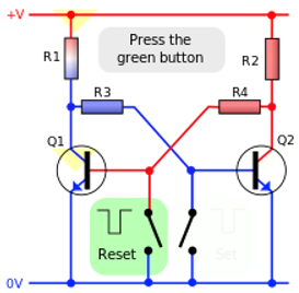
Figure . Bistable multivibratorIt is called as bistable latch of flip flops. Schmitt trigger is another bistable circuit which is an important property of the bistable multivibrator where it maintains the given output voltage level unless an external signal is applied .Application of external signal causes a change of state and this output level is maintained indefinitely until a second trigger is applied .Thus a bistable multivibrator requires two external trigger before it returns to its initial state.Q 7) Explain the working of fixed bias multivibrator?A 7)
Figure . Fixed Bias Multivibrator In fixed-bias bistable multivibrators the device is biased by two different sources. The circuit consists of two identical transistors Q1 and Q2 and the output of each is given as input to the other. R1 and R2 are the part of the feedback network. The collector resistances RC1 and RC2 are equal.Working:When power supply is provided both the transistors are in conducting state. Since the two transistors are not equivalent and show variation one transistor conducts more than the other. When Q1 conducts the collector, potential start dropping. This low potential is fed to the base of transistor Q2 through resistor R2. Due to the applied low voltage, the conducting state of Q2 drops which causes the collector potential of transistor Q2 to increase. The increased potential is then fed to the base of transistor Q1 through resistor R1. This potential puts the transistor in more forward biased condition. Due to this cumulative action, Q1 reaches saturation and Q2 reaches cutoff. The output is from the collector of transistor Q2 through CC. Hence, the first stable state achieved is 1. When a negative trigger pulse of high magnitude and short duration is provided to the base of transistor Q2 through capacitor C1. This trigger pulse causes a reduction in the forward biasing provided to the transistor Q1. Due to this, Q1 now conducts less than the previous case. This leads to an increase in the collector potential of transistor Q1. The increased voltage is then given to the base of transistor Q2. This causes Q2 to conduct more than earlier. Thus, a low voltage is achieved at the collector of transistor Q2. This low voltage is fed back to the base of transistor Q1. This causes it to conduct less thus generating a high potential at the collector of transistor Q1. This successive cycle drives Q1 to cutoff and Q2 to saturation. To have transition from current stable state to the next stable state, another triggering pulse is required to provide. The output of the bistable multivibrator is shown below:
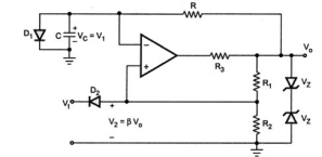
Figure . Output Waveform Q 8) Explain the working of monostable multivibrator using collector coupled amplifier?A 8)The monostable multivibrator is called as the one-shot multivibrator. The circuit produces a single pulse of specified duration in response to each external trigger signal. For such a circuit, only one stable state exists. When an external trigger is applied, the output changes its state. The new state is called as a quasi-stable state. The circuit remains in this state for a fixed interval of time. After some time it returns back to its original stable state with the help of internal trigger signal . Usually, the charging and discharging of a capacitor provide this internal trigger signal.
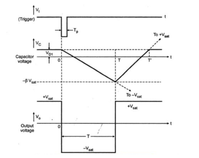
The diode D1 connected across the capacitor is called clamping diode. It clamps the capacitor voltage to 0.7V when the output is at + Vsat . A negative triggering pulse is applied to the Non-inverting terminal of Op-amp through RC differentiator circuit and diode D2. Operation of the Circuit (i). To understand the operation of the circuit, let us assume that the output Vo is at +Vsat that is in its stable state.(ii). The diode D1 (Connected across Capacitor) conducts and the voltage across the capacitor C - Vc gets clamped to 0.7 Volts.(iii). The voltage at the non-inverting terminal is controlled by voltage divider circuit of R1 and R2
Voltage at non-inverting terminal (VB2) = β Vo β= R2/ R1 + R2 (iv). If VT , a negative trigger of amplitude VT is applied to the non-inverting terminal, so that the effective voltage at this terminal is less than 0.7 V then the output of the Op-amp changes its state from to + Vsat to -Vsat .(v). The diode is now reverse biased and the capacitor starts charging exponentially to -Vsat through resistance R.(vi). The voltage at the non-inverting terminal is now -βVsat. When the capacitor voltage becomes just slightly more negative than -βVsat , the output of the Op-amp changes its state back to + Vsat(vii). The capacitor now starts charging towards + Vsat through R until Vc reaches 0.7V as capacitor gets clamped to the voltage.Expression for pulse width TInitial voltage ( at t=0 ) across Capacitor = Vco = VD1
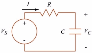
The supply Voltage is the output voltage Vs = Vo = -VsatVoltage across Capacitor at time t is given by the eqVc(t) = VD1 e -t/RC + Vo(1 -e -t/RC) At time t=T Vo= -Vsat Vc(T) = - βVsat Vc(t) = ( VD1 – Vo) e -t/RC + Vo - βVsat = (VD1 + Vsat ) e -T/RC – Vsat T = RC ln (1 + VD1 / Vsat ) / 1 - ββ=R2 / R1 + R2 If Vsat >> VD1 and R1 = R2 T= 0.69 RC For Monostable operation, the trigger pulse width Tp should be much less than T. Q 9) Explain the working of astable multivibrator using collector coupling?A 9)Astable multivibrator:
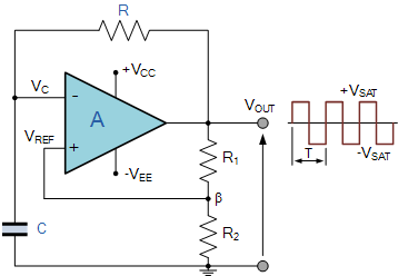
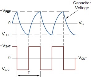
Figure. Astable Multivibrator Let us assume that the capacitor is fully discharged and the output of the op-amp is saturated at the positive supply rail. The capacitor, C starts to charge up from the output voltage, Vout through resistor, R at a rate determined by their RC time constant.In RC circuits that the capacitor charges up fully to the value of Vout which is +V(sat)). However, as soon as the capacitors charging voltage at the op-amps inverting (-) terminal is equal to or greater than the voltage at the non-inverting terminal, thus the output will change state and be driven to the opposing negative supply rail.The sudden reversal of the output voltage causes the capacitor to discharge toward the new value of Vout at a rate dictated again by their RC time constant.Op-amp Multivibrator Voltages
Once the op-amps inverting terminal reaches the new negative reference voltage, -Vref at the non-inverting terminal, the op-amp once again changes state and the output is driven to the opposing supply rail voltage, +V(sat). The capacitor sees a positive voltage across its plates and the charging cycle begins again. Thus, the capacitor is constantly charging and discharging creating an astable op-amp multivibrator output.The period of the output waveform is determined by the RC time constant of the two timing components and the feedback ratio established by the R1, R2 voltage divider network which sets the reference voltage level. If the positive and negative values of the amplifiers saturation voltage have the same magnitude, then t1 = t2 and the expression to give the period of oscillation becomes:β=R2/ R1 + R2 T = 2 RC x ln(1+β/1-β) since f=1/T Where: R is Resistance, C is Capacitance, The frequency of oscillation for an Op-amp Multivibrator circuit not only depends upon the RC time constant but also upon the feedback fraction. However, if we used resistor values that gave a feedback fraction of 0.462, (β = 0.462), then the frequency of oscillation of the circuit would be equal to just 1/2RC as shown because the linear log term becomes equal to one.Q10) An op-amp multivibrator circuit is constructed using the following components. R1 = 35kΩ, R2 = 30kΩ, R = 50kΩ and C = 0.01uF. Calculate the circuits frequency of oscillation.A 10)β=R2/ R1 + R2 = 30K/ 35K + 30K =0.462 T = 2RC ln(1+β/1-β) = 2RC ln (1+0.462/1-0.462)T = 2 x (50K Ω x 0.01x μF) x ln (2.717) T = 0.001 x 1 = 0.001 sec or 1 msec f = 1/T = 1/0.001 = 1,000 Hz or 1kHz
|
|
|
|
|
|
|
|
|
|
|
0 matching results found
