AWP
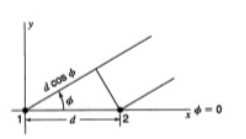
Unit-2Antenna Arrays Q.1 Explain Isotropic point sources of same amplitude and phase.Ans – 1. Two point sources 1 and 2 are seperated by d & located symmetrically with respect to the origin.2.The origin of the co-ordinates is taken as the reference for the phase.3.In the direction of φ, the fields from sources 1 and 2 are retarded and advanced respectively by  d,cosφWhere, d=
 =kd
=kd
Figure : Isotropic point sources of same amplitude and phase
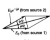
Figure : Vector addition
Figure : Phase of total field4. This figure shows the phase of total field as a function of φ for two isotropic point sources of same amplitude and phase spaced  apart.The phase change is zero when refferd to the centre point of the array but is
  as shown by the dashed curve when referred to source 1.
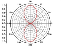
Figure: Isotropic point sources pattern of same amplitude and phase5.Total field at a distance r in φ direction isE=E0 e-jΨ/2 + E0 e +jΨ/2Where Ψ(φ)= kd cos(φ)E= 2 E0 cos E= 2 E0 cos
 |E|= cos
 6.Field from source in φ direction is advanced by Ψ =d, cosφWhere, d=
 =kd E=E0 e +jΨ = E=E0 e +jΨ/2 ( e-jΨ/2 + +jΨ/2) E= 2 E0 cos
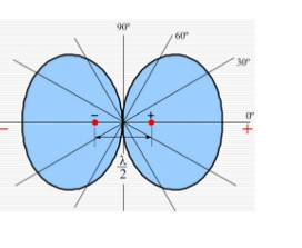
 Q.2.Write a short note on Isotropic point sources of same amplitude and opposite phaseAns-– 1. Two point sources 1 and 2 are two sources are in opposite phase.
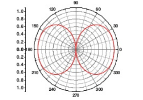
Figure: Isotropic point sources pattern of same amplitude and opposite phase E=-E0 e-jΨ/2 + E0 e +jΨ/2E= 2j E0 sin |E|= sin
 Ex. E= sin
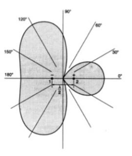
  Q.3. Explain in detail Isotropic point sources of same amplitude and in phase quadratureAns- 1.Let sorces 1 and 2 be retarded and advanced respectively, both by
Figure: Isotropic point sources pattern of same amplitude and in phase quadrature for spacing  .2. This figure shows the field pattern of two isotropic point sources of same amplitude and in phase quadrature for a spacing of
  . The source to the right leads that to the left by 900.
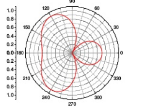
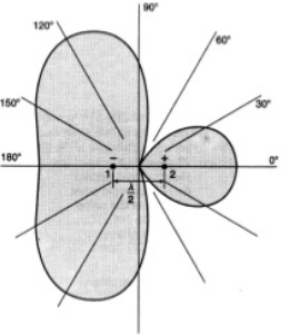
Figure: Isotropic point sources pattern of same amplitude and in phase quadrature for spacing  .3. This figure shows the field pattern of two isotropic point sources of same amplitude and in phase quadrature for a spacing of
  . The source 2 leads source 1by 900. E=E0 e-j(
 ) + E0 e+j(
 ) =2E0 COS ((
 )+
)+ )|E|= cos
 Q.4 Explain Isotropic point sources of same amplitude and any phase differenceAns- 1.Two point sources 1 and 2 are seperated by d having same amplitude.2. The origin of the co-ordinates is taken as the reference for the phase.3.Total phase difference Ψ between fields from sources 2 & 1 in φ direction.
Figure: Isotropic point sources of same amplitude and any phase differenceE=E0 e-jΨ/2 + E0 e +jΨ/2E= 2 E0 cos E= cos
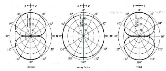
 Q.5 What is the principle of Pattern multiplication?Ans- Principle of pattern multiplication“The total far-field radiation pattern |E| of array (array pattern) consists of the original radiation pattern of a single array element multiplying with the magnitude of the array factor |AF|. This is a general property of antenna arrays and is called the principle of pattern multiplication.”
Figure: Array pattern of two-element arraysQ.6 Write expression for null direction and half power beam width of linear array of n isotropic point of equal magnitude and spacing.Ans- E norm =  For finding direction of Nulls:Sin (
 )= 0For broadside array:
 cos φ0 = +
 and -
and - 1. For general case, Null direction array length,
 2. For Broadside, Null direction array length,
 And beam width between first nulls(long array)
 3. For Ordinary end fire, Null direction array length,
 And beam width between first nulls( long array)
 4. For End fire with increased directivity
 5. And beam width between first nulls (long array)
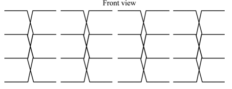
Figure: First null beam widthQ.7 Explain Broadside Array.Ans-1. The broadside array is defined as “the radiation pattern's direction is perpendicular or broadside to the array axis”.2. It uses the dipole elements that are fed in phase and separated by the one-half wave length. A broadside array is a type of antenna array which is used to radiate the energy in specific direction to make better transmission. 3. It is a bidirectional array which can send and receive process at both ends (sending and receiving end).4. The front view of the broadside array is shown below.
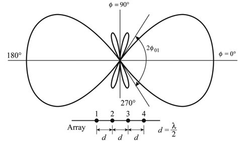
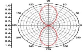
Figure: Broadside ArrayFrom this Figure 1, the broadside array is at extreme right angle direction to the array plane. However, due to pattern cancellation in the path joining at the center, the radiation pattern is too less.5.Radiation patternThere are different types antenna array present. Each have their own radiation pattern. The broadside array's pattern is drawn and shown below.
Figure: Radiation pattern6. This pattern is at right angles to the plane and is bi-directional. The radiation beam has very narrow pattern and has high gain.Write the formula to find Etotal in the plane. * AFHere, Array factor is denoted by AF, Total radiation pattern is denoted as Etotal and 7. The radiation pattern at single element is denoted as Eat single element.Write the series to find array factor in n-element.AF =
  Here, Relative phase is denoted by ψ.Write expression to find relative phase.
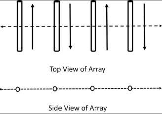
 Here, the array element distance is denoted as d, Constant parameter is denoted as k, Path is denoted as β, and Angle calculated from the z-axis is denoted as θ. Q.8 Write a note on End- fire array.Ans – 1. The physical arrangement of end-fire array is same as that of the broad side array. The magnitude of currents in each element is same, but there is a phase difference between these currents. 2. This induction of energy differs in each element, which can be understood by the following diagram.
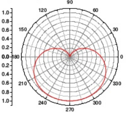
Figure 2.8.1. End- fire arrayThe above figure shows the end-fire array in top and side views respectively.3. There is no radiation in the right angles to the plane of the array because of cancellation. The first and third elements are fed out of phase and therefore cancel each other’s radiation. Similarly, second and fourth are fed out of phase, to get cancelled.4. The usual dipole spacing will be λ/4 or 3λ/4. This arrangement not only helps to avoid the radiation perpendicular to the antenna plane, but also helps the radiated energy get diverted to the direction of radiation of the whole array. Hence, the minor lobes are avoided and the directivity is increased. The beam becomes narrower with the increased elements.5. Radiation PatternThe Radiation pattern of end-fire array is uni-directional. A major lobe occurs at one end, where maximum radiation is present, while the minor lobes represent the losses.
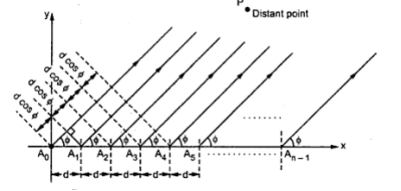
Figure: Radiation pattern The figure explains the radiation pattern of an end-fire array. Figure 1 is the radiation pattern for a single array, while figures 2, 3, and 4 represent the radiation pattern for multiple arrays. Q.9 Explain linear arrays of n isotropic point source of equal amplitude and spacingAns-1. Uniform array has identical elements, identical magnitude, progressive phase and also uniform spacing. 2. At higher frequencies, for point-to-point communications it is necessary to have a pattern with single beam radiation. Such highly directive single beam pattern can be obtained by increasing the point sources in the arrow from 2 to n say. 3. An array of n elements is said to be linear array if all the individual elements are spaced equally along a line. An array is said to be uniform array if the elements in the array are fed with currents with equal magnitudes and with uniform progressive phase shift along the line. 4. Consider a general n element linear and uniform array with all the individual elements spaced equally at distance d from each other and all elements are fed with currents equal in magnitude and uniform progressive phase shift along line as shown in the Fig.
Figure: Linear arrays of n isotropic point source of equal amplitude and spacing5. E TOTAL = E1 + E2 +…….+ EN
 Q.10 Write a note on non-isotropic but similar point sourcesAns – 1. Field pattern of an array of similar non isotropic point sources is equal to the addition of phase pattern of individual array and phase pattern of an array of isotropic sources with same location, relative amplitude and phase.● Applied to arrays of any number of similar sources.● For field magnitude only.2. Phase pattern of an array of similar non isotropic point sources is equal to the addition of phase pattern of individual source and phase pattern of an array of isotropic sources with same location, relative amplitude and phase.3. Thus, total field E isE = f (θ,φ) f(θ,φ) ej|f((θ,φ))+ f((θ,φ)|
 d,cosφWhere, d=
 =kd
=kd
|
|
|
 apart.The phase change is zero when refferd to the centre point of the array but is
  as shown by the dashed curve when referred to source 1.
|
 E= 2 E0 cos
 |E|= cos
 6.Field from source in φ direction is advanced by Ψ =d, cosφWhere, d=
 =kd E=E0 e +jΨ = E=E0 e +jΨ/2 ( e-jΨ/2 + +jΨ/2) E= 2 E0 cos
 Q.2.Write a short note on Isotropic point sources of same amplitude and opposite phaseAns-– 1. Two point sources 1 and 2 are two sources are in opposite phase.
|
 |E|= sin
 Ex. E= sin
  Q.3. Explain in detail Isotropic point sources of same amplitude and in phase quadratureAns- 1.Let sorces 1 and 2 be retarded and advanced respectively, both by
|
 .2. This figure shows the field pattern of two isotropic point sources of same amplitude and in phase quadrature for a spacing of
  . The source to the right leads that to the left by 900.
|
 .3. This figure shows the field pattern of two isotropic point sources of same amplitude and in phase quadrature for a spacing of
  . The source 2 leads source 1by 900. E=E0 e-j(
 ) + E0 e+j(
 ) =2E0 COS ((
 )+
)+ )|E|= cos
 Q.4 Explain Isotropic point sources of same amplitude and any phase differenceAns- 1.Two point sources 1 and 2 are seperated by d having same amplitude.2. The origin of the co-ordinates is taken as the reference for the phase.3.Total phase difference Ψ between fields from sources 2 & 1 in φ direction.
|
 E= cos
 Q.5 What is the principle of Pattern multiplication?Ans- Principle of pattern multiplication“The total far-field radiation pattern |E| of array (array pattern) consists of the original radiation pattern of a single array element multiplying with the magnitude of the array factor |AF|. This is a general property of antenna arrays and is called the principle of pattern multiplication.”
|
 For finding direction of Nulls:Sin (
 )= 0For broadside array:
 cos φ0 = +
 and -
and - 1. For general case, Null direction array length,
 2. For Broadside, Null direction array length,
 And beam width between first nulls(long array)
 3. For Ordinary end fire, Null direction array length,
 And beam width between first nulls( long array)
 4. For End fire with increased directivity
 5. And beam width between first nulls (long array)
|
|
|
 * AFHere, Array factor is denoted by AF, Total radiation pattern is denoted as Etotal and 7. The radiation pattern at single element is denoted as Eat single element.Write the series to find array factor in n-element.AF =
  Here, Relative phase is denoted by ψ.Write expression to find relative phase.
 Here, the array element distance is denoted as d, Constant parameter is denoted as k, Path is denoted as β, and Angle calculated from the z-axis is denoted as θ. Q.8 Write a note on End- fire array.Ans – 1. The physical arrangement of end-fire array is same as that of the broad side array. The magnitude of currents in each element is same, but there is a phase difference between these currents. 2. This induction of energy differs in each element, which can be understood by the following diagram.
|
|
|

 Q.10 Write a note on non-isotropic but similar point sourcesAns – 1. Field pattern of an array of similar non isotropic point sources is equal to the addition of phase pattern of individual array and phase pattern of an array of isotropic sources with same location, relative amplitude and phase.● Applied to arrays of any number of similar sources.● For field magnitude only.2. Phase pattern of an array of similar non isotropic point sources is equal to the addition of phase pattern of individual source and phase pattern of an array of isotropic sources with same location, relative amplitude and phase.3. Thus, total field E isE = f (θ,φ) f(θ,φ) ej|f((θ,φ))+ f((θ,φ)|
|
0 matching results found
