|
|
|
|
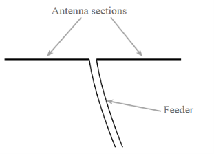
Q.5. Explain Folded Dipole AntennaAns-1. The folded dipole antenna consists of a basic dipole, but with an added conductor connecting the two ends together. This makes a ‘loop’ of wire that is a short circuit to DC. As the ends appear to be folded back, the antenna is called a folded dipole antenna.2. The basic format for the folded dipole aerial is shown below. Like the basic dipole, the folded dipole antenna is a balanced antenna, and needs to be fed with a balanced feeder. 3. Unbalanced feeders can be used provided that a balun (unbalanced to balanced transformer) is used.
|
● Increase in impedance
When higher impedance feeders need to be used, or when the impedance of the dipole is reduced by factors such as parasitic elements, a folded dipole provides a significant increase in impedance level that enables the antenna to be matched more easily to the feeder available.● Wide bandwidth
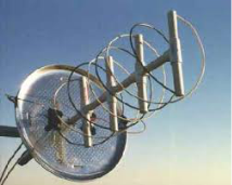
The folded dipole antenna has a flatter frequency response - this enables it to be used over a wider bandwidth with many transmissions utilising a variety of different selectable channels, e.g. television and broadcast radio, a wide bandwidth antenna is needed. The standard dipole antenna does not always provide the required bandwidth and the additional bandwidth of the folded dipole meets the requirements. Q.6 Give the applications of folded dipole antenna.Ans-There are many ways in which folded dipoles can be used. They find uses in many applications:1. On their ownFolded dipole antennas are sometimes used on their own, but they must be fed with a high impedance feeder, typically 300 ohms. This on its own can be very useful in certain applications where balanced feeders may be used.2. As part of another antennaHowever folded dipoles find more uses when a dipole is incorporated in another RF antenna design with other elements nearby. The issue is that incorporating a dipole into an antenna such as a Yagi where elements are closely coupled reduces the feed impedance. If a simple dipole was used, then the feed impedance levels of less than 20 Ω or less can easily be experienced.3. Using a folded dipole enables the impedance to be increased by a factor of four or whatever is required by having multiple wires in the folded dipole.4. Increased bandwidthSometimes folded dipoles may be employed purely to give a greater bandwidth. When used to increase bandwidth, folded dipoles may be used on their own or within another antenna system.Q.7 Write a note on Helical AntennaAns-1. Helical antenna is an example of wire antenna and itself forms the shape of a helix. This is a broadband VHF and UHF antenna.2. Frequency RangeThe frequency range of operation of helical antenna is around 30MHz to 3GHz. This antenna works in VHF and UHF ranges.3. Construction & Working of Helical Antenna● Helical antenna or helix antenna is the antenna in which the conducting wire is wound in helical shape and connected to the ground plate with a feeder line. ● It is the simplest antenna, which provides circularly polarized waves. It is used in extra-terrestrial communications in which satellite relays etc., are involved.
|
|
|
|
● In the case of a vertical arrangement, the two or more antennas can be stacked one above the other. While in a horizontal manner these can be arranged in broadside.
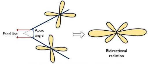
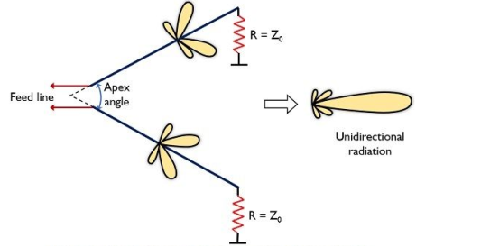
● Here is no reflector is used in case of the array with elements as V antenna.
|
|
● Driven element: The driven element is the Yagi antenna element to which power is applied. It is normally a half wave dipole or often a folded dipole.
● Reflector: The reflector element is made to be about 5% longer than the driven element. The Yagi antenna will generally only have one reflector. This is behind the main driven element, i.e. the side away from the direction of maximum sensitivity.
● Further reflectors behind the first one makes no noticeable different to the antenna performance. However, many designs use reflectors consisting of a reflecting plate, or a series of parallel rods simulating a reflecting plate. This gives a slight improvement in performance, reducing the level of radiation or pick-up from behind the antenna, i.e. in the backwards direction. Tis can help
in reducing the levels of interference received.Typically a reflector will add around 4 or 5 dB of gain in the forward direction.
● Director: The director or directors are made to be shorter than the driven element. There may be none, one of more reflectors in the Yagi antenna. The director or directors are placed in front of the driven element, i.e. in the direction of maximum sensitivity. Typically, each director will add around 1 dB of gain in the forward direction, although this level reduces as the number of directors increases.
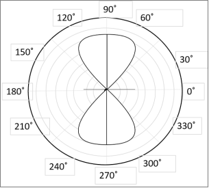
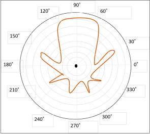
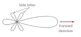
Q.11 Draw and explain radiation Pattern of yagi-uda antenna.Ans-
|
