Back to Study material
CS

UNIT-1MODELLING IN THE FREQUENCY DOMAIN Q1) Find SFG for the block diagram below?

A1)

Ra+cb =cc/R= a/1-bQ2) The SFG shown has forward path and singles isolated loop determine overall transmittance relating X3 and X1­?

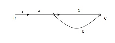
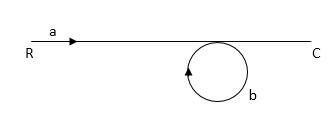
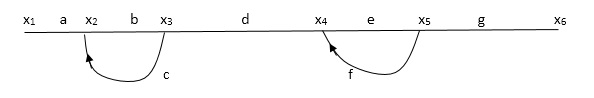
A2)

 X1- I/p node

 X2-Intenmediale node

 X3- o/p node

 ab- forward path (p)

 bc- 1 loop (L)

At node XQ:

 X2 = x1a + x3c [Add i/p signals at  node]

At node x3:

  x2b =x3

                          (x1a+x3c) b = x3

  X1ab = x3 (1-bc)

  X1 = x3 (1-bc)/ab

  Ab/(1-bc) = x3/x1

                             T= p/1-L

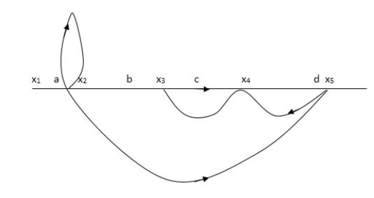
X1:- I/p node    x2, x3,x4,x5,Qnlexmedili node

X0:- o/p node  abdeg:- forward path

  bc, ef :- Loop [isolated] 

x2 = ax1+c x3

x3= bx2

x4 = d x3+f x5

x5 = e x4

x6= g x5

x6 = g(e x4) = ge [dx3+ e f x5]

xb = ge [d (bx2) + f (e x4)]

xb = ge [ db (ax1+cx3) + fe (dx3+ fx5)]

xb = ge [db (ax1+cb (ax1+x3) +fe[cdbx2]+

 f( e [db (ax1+ cx3)

x2 = ax1 + cb (x2)  x4 = d bx2 + f exq

x2 = ax1 + cbx2          = db (d4) + fe/1-cb

x2 = ax1/(1-cb)   xy = db x2 + f x6/g

  xy = db [ax1]/1-cb + f xb/g

x5 = c db ( ax1)/1-cb + efxb/g

xb = gx5

= gedb (ax1)/1-cb + g efxb/g

 Xb = gx5

 gedb (ax1)/1-cb + g efxb/g

(1-  gef/g) xb = gedb ax1/1-ab

Xb/x1 = gedb a/ (1- ef – bc + beef

Xb/x1 = p/ 1- (L1+L2) + L1 L2 for isolated loops.

Q3) Reduce given B.D to canonical (simple form) and hence obtain the equivalentTf = c(s)/ R(S) ?

A3)


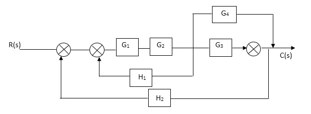
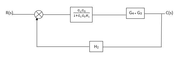
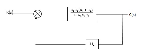
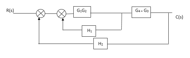
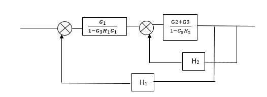
C(S)/R(S) = (G1G2) (G3+G4)/1+G1G2H1)/1-G1,G2(G3+G4) H2/1+G1G2H1

= G1G2(G3+G4)/1+G1G2H1-G1G2H2(G3+G4)

=G1G2(G3+G4)/1+(H1-H2)(G1G2) (G3+G4)

C(s)/R(S) = G1G2(G3+G4)/1+(H1-H2(G3+G4)) G1 G2

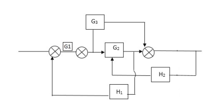
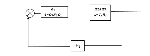
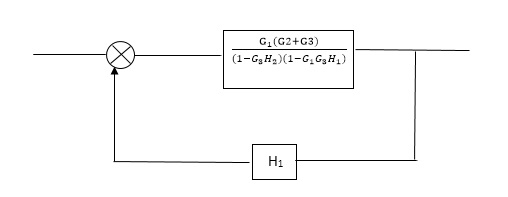
Reduce the Block diagram
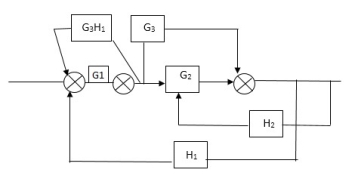
 

C(s)/R(s)=  G1(G3+G2)/(1-G1G3X1) (1-G2X2) H1= G(G3+G2)/(1-G3G1H1) (1-G2H2) + G1H1(G3+G2)= G1(G3+G2)/1-63G1H1-G2H2+G1H1(G3+G2H1=G1(G3+G2)/1-G3H2+G1G2H1(1+G3H2)Q4) Reduce using Masons gain formula

A4)
P1= G1 p2 =G2 Delta1 =1

L1= -G1 H1

= 1-(-G1H1)

 = 1+G1H1

T= G1+G2/1+G1H1

Q5) Determine overall gain reliably x5 and x1 Draw SFGX2 = ax1+ f x2         X3= bx2 +exy        X4 = cx3+hx5        X5 =dx4 + gx2A5)

P1 = abcd       p2 = ag

L1 = f   L2 = ce, L3= dh

1 = 1

2= 1-ce

= 1-[L2+L2+L3] + [L1 L2 +L1 L3]

 = 1-[f+ le = dh] + [fce +fdh]

T= abcd+ ag (1-ce)/1-[ftce + dh ] + (fce + fdh)

      Q6)  Draw the  free body diagram and write the differential equation for system below.

A6) The free body diagram for M1 will be

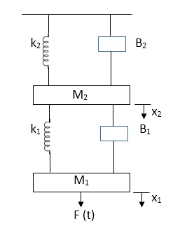
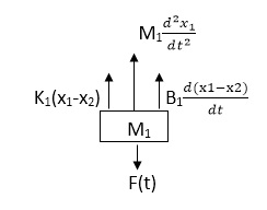
F(t) = M1 d2/dt2x1+ B1 d/dt (x1-x2)+ k1(x1-x2)

Similarly for M2we have

K1(x1-x2) + B1d/dt(x1-x2) = k2x2+M2d2/dt2+B2dx2/dt

 Q7) for the given mechanical system below draw the analogus system (force. Voltage )& find V0(s)/V1(s)

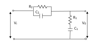
A7)

Let     Z1   = R2 11 1/c2

    =R2*1/c2s/R2+1/c2s

 Z1= R2/1+R2c2s

  Let     Z2 = R1+1/c1s

 Z2= 1+R1c1s/c1s

V0(s)/vi(s) = z2/z1+z2

      = 1+R1c1s/c1s/R2/1+R2c2s+1+R1c1s/c1s

V0(s)/v0(s) =(c1+R1c1s) (1+R2c2s)/R2c1s+1+sR1c1s2R1R2c1c2

 Q8) Compare open and closed loop system?A8)Open loop systems: This is the loop of control system without any feedback. In this the control action is not dependent on the desired output.

Fig. 1 open loop control systemExample of open Loop systems are the traffic signals, Automatic washing machine and in fields control d.c. motor.Closed loop systems: This is a type of control system with feedback. In this type of system The control action is dependent on the desired output.

Fig 2 Closed Loop control systemThe error signal is again fed to controller to the error and get desired output.Q9) List the properties of Laplace Transform? A9) Properties of Laplace Transform:
  • Linearity Property:
  • If f1(t) and f2(t) are two functions of time. Then, in domain of convergence

    L[a f1(t)+b f2(t)]=a + b

                                =aF1(s)+bF2(s)

  • Differentiation Property:
  • If x(t) is function of time then Laplace transform of nth derivative is given as

  • Integration Property:
    • The Laplace of nth order integral is given as
    • L[]= +
    • L[f-n(t)]=+++……….
    • As ……..=0. Hence
    • L[f-n(t)]=
     Q10) Derive the transfer function for thermal systems?A10) Thermal systems are those that involve the transfer of heat from one substance to another. The model of thermal systems is obtained by using thermal resistance and capacitance which are the basic elements of the thermal system. The thermal resistance and capacitance are distributed in nature. But for simplicity in analysis lumped parameter models are used.Consider a simple thermal system shown in the below figure. Let us assume that the tank is insulated to eliminate heat loss to the surrounding air, there is no heat storage in the insulation and liquid in the tank is kept at uniform temperature by perfect mixing with the help of a stirrer. Thus, a single temperature is used to describe the temperature of the liquid in the tank and of the out flowing liquid. The transfer function of thermal system can be derived as shown below.

    Fig 3 Thermal SystemLet        θ1 = Steady state temperature of inflowing liquid, °C               θ0 = Sandy state temperature of outflowing liquid, °C               G = Steady state liquid flow rate, Kg/sec               M = Mass of liquid in tank, Kg                c = Specific heat of liquid, Kcal/Kg °C                R = Thermal resistance, °C - sec/Kcal                C = Thermal capacitance, Kcal/°C                Q = Steady state heat input rate, Kcal/Sec 
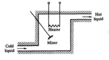
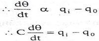
    Let us assume that the temperature of inflowing liquid is kept constant. Let the heat input rate to the thermal system supplied by the heater is suddenly changed from Q to Q + q1. Due to this, the heat output flow rate will gradually change from Q to Q + q0. The temperature of the outflowing liquid will also be changed from θ0  to  θ0 + θ. For this system the equation for q0, C and R is obtained as follows,

    transfer-function-mathematical-model-thermal-system

    Thermal capacitance, C = Mass, M x Specific heat of liquid, c = Mc 

    transfer-function-mathematical-model-thermal-system

    On substituting for qo from equation (1) in equation (3) we get, 

    In this thermal system, rate of change of temperature is directly proportional to change in heat input rate.


    The constant of proportionality is capacitance C of the system.Equation (5) is the differential equation governing system. Since, equation (5) is of first order equation, the system is first order system.

    From equation (3) ,   R = θ/q0  

    q0 = θ/R
    On substituting for q0 from equation (6) in equation (5) we get,

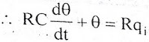
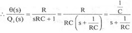
    Let, L {θ} = θ(s); L{dθ/dt} = sθ(s) ; L{q1} = Q1(s) 

    On taking Laplace transform of equation (7) 

     RC s θ(s) + θ(s) = R Q1(s)

     θ(s) [sRC + 1] = R Q1(s)
     θ(s)/Q1(s)  is the required transfer function of thermal system.