Back to Study material
CS

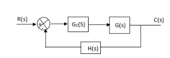
UNIT-6FEEDBACK CONTROL SYSTEM Q1) The block diagram of a system using PI controllers is shown in the figure 1 Calculate:(a). The steady state without and with controller for unit step input?(b). Determine TF of newly constructed sys. With controller so, that a CL Poles is located at -5?

Fig 1 Block diagram with PI controllerA1)

(a). Without :

C(S)/R(S) = 0.2/(S + 1)

C(S) = R(S) 0.2/(S + 1) + 0.2

For unit step

ess = 1/1 + Kp

Kp = lt G(S)

S 0

= lt   0.2/(S + 1)

S 0

Kp = 0.2

ess = 1/1.2 = 5/6 = 0.8

(b). With controller :

Gc(S) = Kp + Ki/S

G’(S) = Gc(S).G(S)

= ( Kp + Ki/S )0.2/(S + 1)

= (KpS + Ki)0.2/S(S + 1)

ess = 1/1 + Kp = 0

So, the value of ess is decreased.

(b). Given

Kpi/Kp = 0.1

G’(S) = (Kp + Ki/S)(0.2/S + 1)

= (KpS + Ki)0.2/S(S + 1)

As a pole is to be added so, we have to examine the CE,

1 + G’(S) = 0

1 + (Kp + Ki)0.2/S(S + 1) = 0

S2 + S + 0.2KpS + 0.2Ki = 0

S2 + (0.2Kp + 1)S + 0.2Ki = 0

Given,

Kpi = 0.1Ki

Kp = 10Ki


S2 + (2Ki + 1)S + 0.2Ki = 0

Pole at S = -5

25 + (2Ki + 1)(-5) + 0.2Ki = 0

-10Ki – 5 + 25 + 0.2Ki = 0

-9.8Ki = -20

Ki = 2.05

Kp = 10Ki

= 20.5


Now,

G’(S) = (KpS + Ki)(0.2)/S(S + 1)

= (20.5S + 2.05)(0.2)/S(S + 1)

G’(S) = 4.1S + 0.41/S(S + 1)

Q2) The block diagram of a system using Pd controller is shown, the PD is used to increase ξ to 0.8. Determine the T.F of controller?

Fig 2 Block diagram with PD controllerA2)

(1). Kp = 1

Without controller:-

C(S)/R(S) = 16/S2 + 1.6S + 16

wn = 4

2 ξwn = 16

ξ = 1.6/2 x 4 = 0.2


(b). With derivative :-

ξS = 0.2 to 0.8

undamped to critically damped,

G’(S) = (1 + KdS)(16)/(S2 + 1.6S)


CE:

S2 + 1.6S + 16(1 + KdS) = 0

S2 + (1.6 + Kd)S + 16 = 0

2 ξwn = 1.6 + Kd1.6

wn = 4

ξS = 0.8

2 x 4 x 0.8 = 1.6 + Kd1.6

6.4 – 1.6 = Kd1.6

4.8/16 = Kd

Kd = 0.3

TF = (1 + 0.3S)16/S(S + 16)


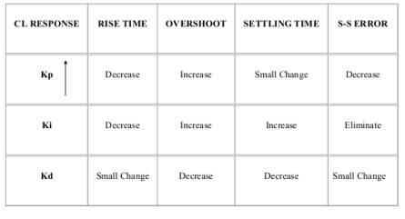
Q3) Compare the controller performances?A3)

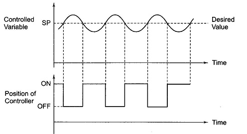
Q4) Explain basic ON-OFF controller?A4) The elements which are used to control only two positions either ON or OFF are called as ON-OFF controllers. They do not operate for any other value. In this kind of system, the output will change in process variable. As the output is affected the process variable again changes in reverse direction and at this stage when the process variable exceeds certain limits the output is closed. As the output is closed the process variable will again change in its normal direction and when the pre-set level is crossed the output is open. This process continues making the valve ON-OFF. These are mainly used in electrical power transformer for cooling purpose.

Fig 3 ON-OFF controllerThe fan used for cooling the transformer uses these controllers. When the temperature (process variable) is more than the present value the fan is turned ON and when temperature comes below the present value the fan is turned OFF. In practical application there is a time lag in the switching of the circuit from ON to OFF and this is defined as dead time. This dead time or delay changes the actual curve of the system. Q5) Explain P controllers?A5) Effects of controller are viewed on time response and stability.

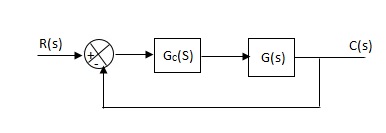
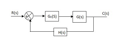
Fig 4 Controller with unity feedback systemGc(S) = TF of the controllerG(S) = OLTF without controllerG’(S) = Gc(S).G(S)= OLTF with controllerProportional means scalar Multiplier.Gc(S) = Kp Stability can be controlled Q6) Explain I controllers?A6) Integral ControllerThe transfer function of this controller is Gc(S) = Ki/SIntegral controller is used to improve the steady state response or reduce the steady state error.

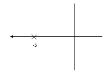
Fig 5 Integral ControllerG’(S) = Gc(S).G(S)G(S) = 1/S + 5, Gc(S) = Ki/SG’(S) = Ki/S(S + 5). After applying the Gc(S) the type of system is increasing and hence, the steady state error is decreasing (Refer Time Response).Disadvantage - By using integral controller, the stability of closed loop system decreases.G(S) = 1/S + 5

Fig 6 Pole Locations For given systemG’(S) = Ki/S(S + 5) 

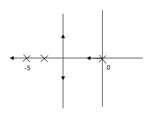
Fig 7 Pole Location after Integral controllerFig (6), is more stable than (7) as more the away the pole from origin (imaginary axis) more is the stability.Q7) Explain D controllers?A7) Derivative Controller

Gc(S) = Kd(S)They are used to improve the stability.

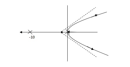
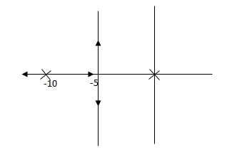
Fig 8 Derivative controller systemG’(S) = KdS/S2(S + 10)

Fig 9 Root Locus for system without controller

Fig 10 Root locus with controllerFig 10 is stable i.e more stable than the Fig 9.Disadvantage – It increases the steady state i.e. o/p will not track the input at steady state.Q8) For system G(S) = 1/S (S + 8) find the system response after P controller is introduced?A8) CLTF = 1/S2 + 8S + 1

w2n = 1

wn = 1

2ξWn = 8

ξ = 4

ξ>/1 so, overdamped.

Now introducing Gc(S) = K

G’(S) = Kp/S(S + 8)

CLTF = Kp/S2 + 8S + Kp

wn = √Kp

2 ξwn = 8

ξ = 4/Kp

If,

Kp = 16; ξ = 1; critically damped

Kp> 16; ξ< 1; undamped

Kp< 16; ξ> 1; overdamped

Q9) Explain how we could get control over the system dynamics by use of feedback?A9)The dynamics of the system can be controlled by the feedback by adjusting the location of poles. In this section we will see how the location of poles effect the dynamics of the system.Let us consider a system which has open loop transfer function of G(s) defined as

G(s) =                                                  (1)

Let K = /

= 1/

The poles for the above system lie at s= - and =1/ is time constant.

The dc gain of the system is given by G(0) = K = /

For closed loop system the transfer function is given by

                              (2)


=

= /(1+K)

The above equation shows that due to feedback the system pole shifts from - to (–+K’). Due to this change the dynamic response of the system is also affected. For studying the dynamic response, we assume that the input to the system is an impulse.

r(t) = (t)

And it can also be written as

R(s) = 1

Taking inverse Laplace transform of equation 1 we get

For open loop system

c(t) = K’

Taking inverse Laplace transform of equation 2 we get

For closed loop system

c(t) = K’

The system dynamic response decays in both the open system as well as closed loop system. The closed loop system time constant is = /(1+K) so its response decays faster than open loop system by factor of (1+K).Q10) Explain Ziegler Nichols method for tuning of controllers?A10)

They proposed the rules for determining values of proportional gain kp, derivative time Td and integral time Ti. They have proposed from (1) methods.   1) First Method: The basic PID controller is shown in figure below. in this method a unit step response of a plant. is obtained if the plant has neither integrator non dominant complex conjugal poles, then the output step curve is of shape s. as shown below. These curves are generated experimentally.

Fig 11 PID CONTROLLER

FIG 12 S-SHAPED RESPONSE CURVEdelay time  -L        calculated by drawingtime constant -j      tangent c(s) / l(s) = ke-l1s / ts+1 The values of KP, Ti and td should be set according to the table suggested by Ziegler Nichols tuning rules shown below.Type of controller

Types of controller

Kp

Ti

Td


P

T/L

00

 0


PI

0.9T/L

L/0.3

0


PID

1.2T/L

2L

0.5L


Controller gain Gc(s)= kp(1+1/Tis+Tds)                                       = 1.2T / L(1+1 / 2LS+0.5 LS)                                       = 1.2t/l+0.6t / L2S+0.6TS                                        = 0.6T(2/L+1/L2S+S)Gc(s)       = 0.6 T(S+1/L)2/SThus , the PID controller has a pole at the origin and double zeros at S=-1/ L
  • Second Method -
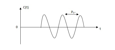
  • 1) firstly set Ti= and Td=02) use proportional control action only, increase kp from 0 to Kcr (Critical value).3)then Kcr and pcr (period) are determined experimentally. 

    Fig 13 closed loop with proportional controller

    Fig 14 sustained oscillation with period pcr.4)For this method Ziegler Nichols suggested new set of values for kp ,ti and td shown in table below. 

    Types of controller

    KP

    TI

    Td

    P

    0.5Kcr

    0

    PI

    0.45 KCR

    1/1.2PCR

    0

    PID

    0.6KCR

    0.5PCR

    0.125PCR


    GC(S) = KP(1.1/Tis+Tds)

                =0.6 Kcr(1+1/0.5PcrS+ 0.125 PCRS)

                 =0.075 KcrPcr(s+4/Pcr)2 / s


    Thus, the PID controller has a pole at the origin and double zeros at s= -4/Pcr