UNIT-6
Application of Digital Signal Processing
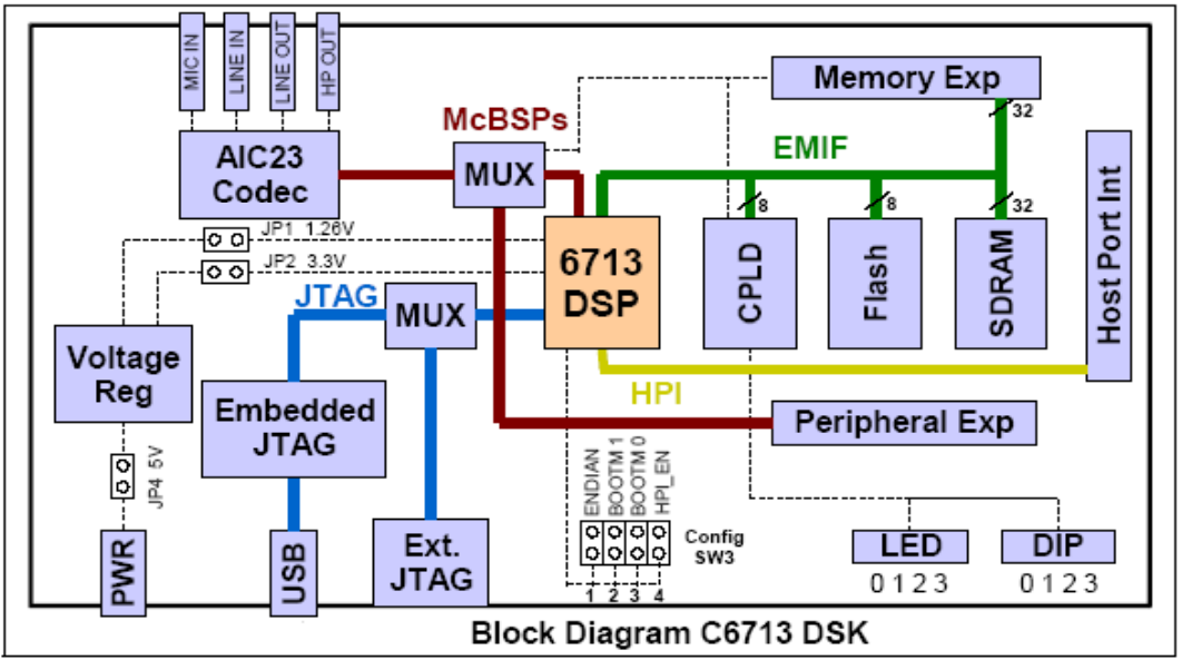
Key features include:
2. Explain use of DSP in ELECTROCARDIOGRAPHY(ECG).
The electrocardiography is better known as an ECG. This technique is used to record the electrical impulses which immediately precede the contractions of the heart muscle. This method causes no discomfort to a patient and is often used for diagnosing heart disorders such as coronary heart disease, pericarditis or inflammation of the membrane around the heart, cardiomyopathy or heart muscle disease arrhythmia and coronary thrombosis.
How an ECG works:
When cell membranes in the heart depolarize, voltages change and currents flow. Because a human can be regarded as a volume conductor, changes in potential are transmitted throughout the body, and can be measured. When the heart depolarizes, it is convenient to represent the electrical activity as a vector between two point charges.
An ECG is recorded by placing electrodes on the surface of the skin.
The ECG measures the electrical activity of the heart. This electrical activity controls the heartbeat. Special cells called pacemakers release bursts of electrical energy which travel through the heart muscle, causing it to contract and relax. There are valve movements between the two cycles. As a result of the electric pulses, the electrodes record some charge. This charge is displayed over a graph paper.
The ECG works in the following steps:
Data is acquired from the electrodes of the ECG. The ECG machine then reads the direction of the flow of the charge in the human body after the amplification.
The heart gives different direction of flow of electric impulse charges during its rhythm. As such, by the detection of the direction of the flow of charges, the rhythmic movement of the hearth can be detected. There are some set parameters for the normal heart rhythms. If there is any abnormality, then it can be judged by comparing with normal values.
Generally, the result of an ECG is obtained on a graph paper as:
This signal is in the form of a wave on the graph paper. This signal can be read in the form of values on the graph.
Advantages- was the first and currently the most effective way of the analysis of the rhythm of the heart.
Disadvantages- External interference of even a very small charge may adversely affect the output.
MRI SCANS: Magnetic resonance imaging is a medical imaging technique used in radiology to visualize detailed internal structures. The good contrast it provides between the different soft tissues of the body make it especially useful in brain, muscles, heart, and cancer compared with other medical imaging techniques such as computed tomography (CT) or X-rays. MRI is a fairly new technique that has been used since the beginning of the 1980s.
The MRI scan uses magnetic and radio waves, meaning that there is no exposure to X-rays or any other damaging forms of radiation.
The patient lies inside a large, cylinder-shaped magnet. Radio waves 10,000 to 30,000 times stronger than the magnetic field of the earth are then sent through the body. This affects the body’s atoms, forcing the nuclei into a different position. As they move back into place they send out radio waves of their own. The scanner picks up these signals and a computer turns them into a picture. These pictures are based on the location and strength of the incoming signals.
Our body consists mainly of water, and water contains hydrogen atoms. For this reason, the nucleus of the hydrogen atom is often used to create an MRI scan in the manner described above.
Using an MRI scanner, it is possible to make pictures of almost all the tissue in the body. The tissue that has the least hydrogen atoms (such as bones) turns out dark, while the tissue that has many hydrogen atoms (such as fatty tissue) looks much brighter. By changing the timing of the radio wave pulses it is possible to gain information about the different types of tissues that are present.
3. Write use of DSP in Image processing
Digital Signal Processing is the way of life of current generation. We are surrounded by innumerable devices which do digital signal processing around you. Most of these devices were analog 2–3 decades before. Now, all of them are digital.
Examples:
4. Write short note on Acoustic Noise Canceller
In ECG recording, there are often is unwanted 60 hertz interference in the recorded data. The analysis show that the interference comes from the power line and include magnetic induction,

Fig: speech samples and spectrum
Displacement current in liquids or in the body of the patient, effects from equipment interconnections, and other imperfections. Although using proper grounding or twisted pairs minimizes such 60 Hz effect, and other effective choice can be use of a digital notch filter, which eliminates the 60 hertz interference while keeping all the other useful information. Figure illustrates A 60 hertz interference eliminator using a digital notch filter. With such enhanced ECG recording, doctors in clinics could give accurate diagnosis for patients.

Fig: Elimination of 60 Hz interference in ECG
5. Explain Low power implementation of DSP in mobile communication.
Speech coding for mobile & VoIP to reduce the bit-rate required for transmitting telephone quality speech, a new approach to speech compression is needed. Current mobile phones compress to about 13,000 b/s (bit per second) and we aim to achieve 4,000 b/s and lower using a method called 'DAP-STC'. Compression is generally achieved by spectrally analyzing speech segments to derive a model of the human speech process. DAP-STC is a new and potentially more accurate way of doing this with a modified speech production model. A variable bit-rate version achieves an average 2,400 b/s and is suitable for packetized speech as may be transmitted over computer networks.
The requirement for extended battery life, reduced size and low electromagnetic interference for mobile communication equipment has led to the development of a novel asynchronous DSP device known as CADRE. Compiler support for the new device is needed to avoid manual assembly-level programming. Apart from maximizing speed and minimizing code size, the compiler is required to produce code which exploits the special features of CADRE to minimize energy consumption. This optimization at software level builds on the economies achieved at hardware design level and aims to minimize the switching activity when the DSP code is implemented.
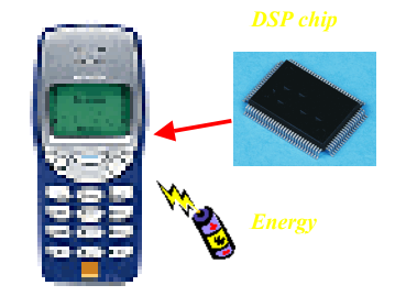
Fig: Mobile for DSP
6. Explain Dynamic range compression
A simple practical example of a nonlinear filtering operation is dynamic range compression, such as occurs in Dolby or DBX noise reduction when recording to magnetic tape (which, believe it or not, still happens once in a while). The purpose of dynamic range compression is to map the natural dynamic range of a signal to a smaller range. For example, audio signals can easily span a range of 100 dB or more, while magnetic tape has a linear range on the order of only 55 dB. It is therefore important to compress the dynamic range when making analog recordings to magnetic tape. Compressing the dynamic range of a signal for recording and then expanding it on playback may be called companding (compression/expansion).
Recording engineers often compress the dynamic range of individual tracks to intentionally flatten'' their audio dynamic range for greater musical uniformity. Compression is also often applied to a final mix. Another type of dynamic-range compressor is called a limiter, which is used in recording studios to soft limit'' a signal when it begins to exceed the available dynamic range. A limiter may be implemented as a very high compression ratio above some amplitude threshold. This replaces hard clipping'' by soft limiting,'' which sounds less harsh and may even go unnoticed if there were no indicator. The preceding examples can be modeled as a variable gain that automatically turns up the volume'' (increases the gain) when the signal level is low, and turns it down when the level is high. The signal level is normally measured over a short time interval that includes at least one period of the lowest frequency allowed, and typically several periods of any pitched signal present. The gain normally reacts faster to attacks than to decays in audio compressors.
7. Draw and explain LPC analysis and synthesis
We can use the linear prediction model to create an analysis/synthesis system: Recall that the linear prediction model, A(z), takes on the form:
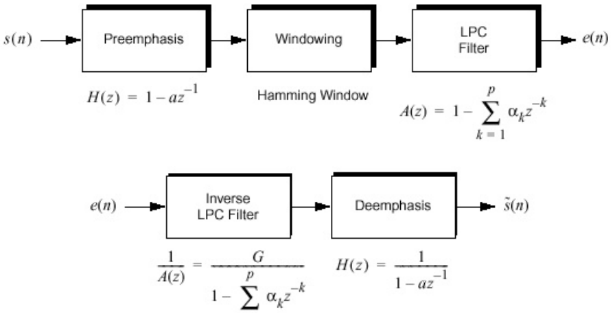
Fig. LPC analysis
This is an all-zero filter which is minimum phase. The inverse of this filter, which is used to synthesize the signal, is an allpole filter. If the autocorrelation method is used to compute the LP coefficients, the filter is guaranteed to be stable.

Note the similarities of this system to our digital model of speech production:
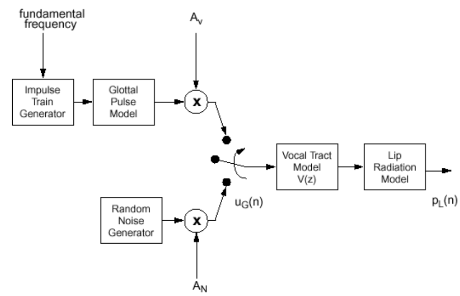
Fig. LPC block diagram
8. Explain SSB modulation in DSP
Once the complex-valued BFO of
e-j(ωcnts) = cos(ωcnts) - jsin(ωcnts)
down-converts the RF SSB to zero Hz, it’s sensible to decimate the multipliers’ outputs to a lower fs sample rate to reduce the processing workload of the Hilbert transformer. We could have performed decimation by a factor greater than 10, but doing so would make the design of the post-D/A analog lowpass filter more complicated. The digital LPFs, whose positive-frequency cutoff frequency is slightly greater than 4 kHz, attenuate any unwanted out-of-baseband spectral energy in the down-converted signal and eliminate any spectral aliasing caused by decimation.
The Delay element in the upper path in Figure 13 is needed to maintain data synchronization with the time-delayed Hilbert transformer output sequence in the bottom path. For example, if a 21-tap digital Hilbert transformer is used, then the upper path’s Delay element would be a 10-stage delay line [2].
With DSP techniques enabling us to implement high performance, guaranteed linear-phase, Hilbert transformation, the phasing method of SSB demodulation has become popular in modern times.

Fig. SSB modulation
9. What is Radar tracking? Explain how it is implemented using DSP.
RADAR transmits radio signals at distant objects and analyzes the reflections. Data gathered can include the position and movement of the object, also radar can identify the object through its "signature" - the distinct reflection it generates. There are many forms of RADAR - such as continuous, CW, Doppler, ground penetrating or synthetic aperture; and they're used in many applications, from air traffic control to weather prediction.
In the modern Radar systems digital signal processing (DSP) is used extensively. At the transmitter end, it generates and shapes the transmission pulses, controls the antenna beam pattern while at the receiver, DSP performs many complex tasks, including STAP (space time adaptive processing) - the removal of clutter, and beamforming (electronic guidance of direction).
The front end of the receiver for RADAR is still often analog due the high frequencies involved. With fast ADC convertors- often multiple channel, complex IF signals are digitized. However, digital technology is coming closer to the antenna. We may also require fast digital interfaces to detect antenna position, or control other hardware. The main task of a radar's signal processor is to make decisions. After a signal has been transmitted, the receiver starts receiving return signals, with those originating from near objects arriving first because time of arrival translates into target range. The signal processor places a raster of range bins over the whole period of time, and now it has to make a decision for each of the range bins as to whether it contains an object or not.
This decision-making is severely hampered by noise. Atmospheric noise enters into the system through the antenna, and all the electronics in the radar's signal path produces noise too. A. Major blocks of modern radar system The major components of modern radar are the antenna, the tracking computer and the signal generator. The tracking computer in the modern radar does all the functions. By scheduling the appropriate antenna positions and transmitted signals as a function of time, keeps track of targets and running the display system.
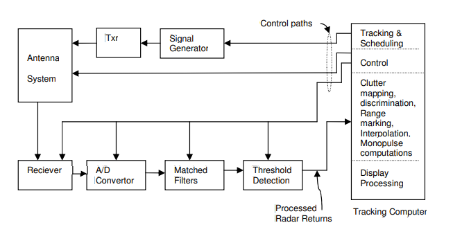
Fig. Block Diagram of a Modern Radar system
Even if atmospheric attenuation can be neglected, the return from a distant object is incredibly weak. Target returns often are no stronger than twice the average noise level, sometimes even buried under it. It is quite difficult to define a threshold for the decision whether a given peak is noise or a real target. If the threshold is too high then existing targets are suppressed, that is, the probability of detection (PD) will drop. If the threshold is too low then noise peaks will be reported as targets, that is, the probability of false alarms (PFA) will rise. A common compromise is to have some 90% probability of detection and a false alarm rate of 10-6 .
It maintains a given PFA known as CFAR, for Constant False Alarm Rate. Rather than keeping the threshold at a fixed point, CFAR circuitry inspects one range bin after the other and compares the signal level found there with the signal levels found in its neighboring bins. If the noise level is rather high in all of these (eg, because of precipitation) then the CFAR circuit will raise the threshold accordingly.
Antenna System Txr Threshold Detection Receiver A/D Convertor Signal Generator Matched Filters Tracking & Scheduling Control Clutter mapping, discrimination, Range marking, Interpolation, Monopulse computations Display Processing Control paths Tracking Computer Processed Radar Returns. Further tasks of the signal processor are:
• Combining information: Secondary surveillance radars like those located on airports can ask an aircraft's transponder for information like height, flight number or fuel state. Pilots may also issue a distress signal via the transponder. The ground radar's signal processor combines this data with its own measurements of range and angular direction and plots them all together on the appropriate spot on the scope.
• Forming tracks: By correlating the data sets which were obtained in successive scan cycles, the radar can calculate a flight vector which indicates an aircraft's speed and expected position for the next scan period. Airport radars are capable of tracking hundreds of targets simultaneously, and flight safety depends heavily on their reliability. Military tracking radars use this information for gun laying or guiding missiles into some calculated collision point.
• Resolving ambiguities in range or Doppler measurements: Depending on the radar's pulse repetition frequency (PRF), the readings for range, Doppler or even both are ambiguous. The signal processor is aware of this and selects a different PRF when the object in question is measured again. With a suitable set of PRFs, ambiguities can be eliminated and the true target position can be determined.
• Ground Clutter Mapping: Clutter is the collective term for all unwanted blips on a radar screen. Ground clutter originates from buildings, cars, mountains etc, and a clutter map serves to raise the decision threshold in areas where known clutter sources are located.
• Time and power management: Within a window of some 60°x40°, phased array radars can instantly switch their beam position to any position in azimuth and elevation. When the radar is tasked with surveying its sector and tracking dozens of targets, there's a danger of either neglecting part of the search sector or losing a target if the corresponding track record isn't updated in time. Time management serves to maintain a priority queue of all the tasks and to produce a schedule for the beam steering device. Power management is necessary if the transmitter circuitry runs the danger of overheating. If there's no backup hardware then the only way of continuing regular operation is to use less power when less power is required, say, for track confirmation.
• Countering interference: Interference can be a) natural, or b) man-made.
Natural interference can be heavy rain or hail storms, but also varied propagation conditions. Man-made interference, if created on purpose, is also called jamming and is one of the means of electronic countermeasures. B. Detection of Signals Detection is the process by which the presence of the target is sensed in the presence of competing indications which arise from background echoes (clutter), atmospheric noise, or noise generated in the radar receiver. The noise power present at the output of the radar receiver can be minimized by using filter, whose frequency response function maximizes the output peak-signal to mean-noise (power) ratio is called matched filter. we shall discuss the application of digital filtering to matched filters.