Unit 4
Design using VHDL
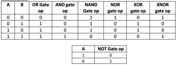
Q1) Explain the design of basic gates?
A1)
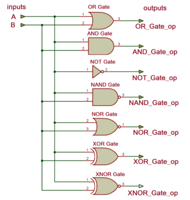
Figure. Logic gates
library IEEE;
use IEEE.STD_LOGIC_1164.ALL;
entity logic_gate is
Port ( A,B : in std_logic;
y_and,y_or,y_nand,y_nor,y_not,y_xor,y_xnor : out std_logic);
end logic_gate;
architecture all_gates of logic_gate is
begin
y_and <= a and b;
y_or <= a or b;
y_nand <= a nand b;
y_nor <= a nor b;
y_not <= not a ;
y_xor <= a xor b;
y_xnor <= a xnor b;
end all_gates;
Q2) Explain combinational circuits design for half adder?
A2) Half Adder
Library ieee;
use ieee.std_logic_1164.all;
entity half_adder is
port(a,b:in bit; sum,carry:out bit);
end half_adder;
architecture data of half_adder is
begin
sum<= a xor b;
carry <= a and b;
end data;

Figure. Half adder waveforms
Q3) Explain the combinational circuit for full subtractor?
A3) Full Subtractor
Library ieee;
use ieee.std_logic_1164.all;
entity full_sub is
port(a,b,c:in bit; sub,borrow:out bit);
end full_sub;
architecture data of full_sub is
begin
sub<= a xor b xor c;
borrow <= ((b xor c) and (not a)) or (b and c);
end data;
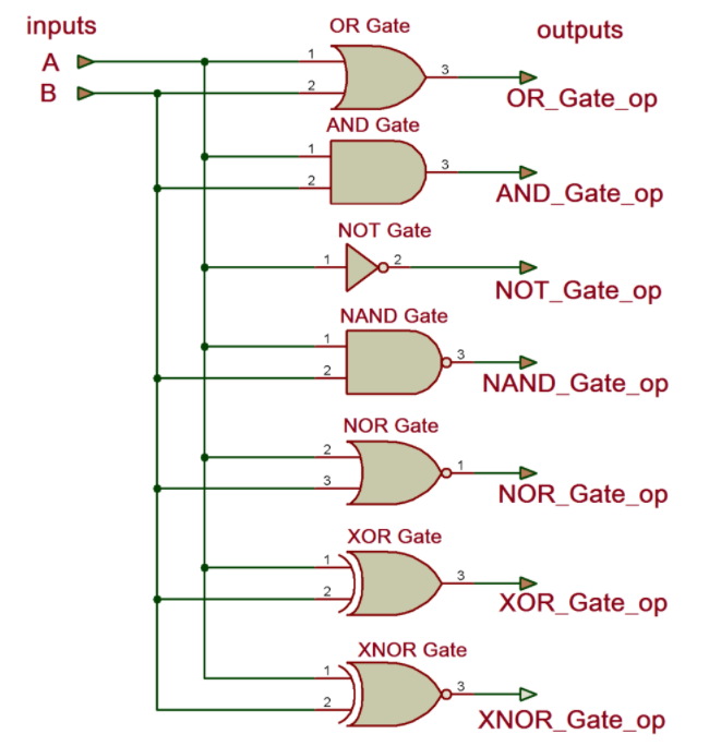
Figure. Full subtractor
Q4) What is datapath explain with example?
A4) Consider the example of an adder that can add 4-values. Assume, we want to add, a, b, c, d. If the output is s, the code can be written as,
s <= ( ( a + b ) + c ) + d ;
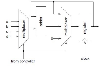
However, this results in a large circuit because the circuit will have 3 adders as shown in the figure,
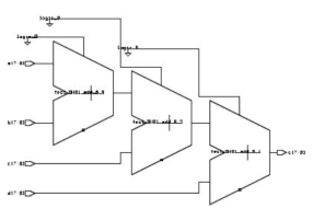
Figure. Adders
use one adder and use it sequentially to add up all the four values. This is when we will need FSM/a control path. Lets take a look how the circuit might look like,
Figure. Control path circuit
To define the data path it works on 2-bit input sel and 1-bit inputs load and clear from the control path.
-- datapath
library ieee ;
use ieee.std_logic_1164.all ;
use ieee.std_logic_arith.all ;
use work.averager_types.all ;
entity datapath is
port (
a, b, c, d : in num ;
sum : out num ;
sel : in std_logic_vector (1 downto 0) ;
load, clear, clk : in std_logic
) ;
end datapath ;
architecture rtl of datapath is
signal mux_out, sum_reg, next_sum_reg :num ;
constant sum_zero :num :=
conv_unsigned(0,next_sum_reg’length) ;
begin
-- mux to select input to add
with sel select mux_out<=
a when "00",
b when "01",
c when "10",
d when others ;
-- mux to select register input
next_sum_reg<=
sum_reg + mux_out when load = ’1’ else
sum_zero when clear = ’1’ else
sum_reg ;
-- register sum
process(clk)
begin
if clk’event and clk = ’1’ then
sum_reg<= next_sum_reg ;
end if ;
end process ;
-- entity output is register output
sum <= sum_reg ;
end rtl ;
The next state is the controller which controls the datapath.
-- controller
library ieee ;
use ieee.std_logic_1164.all ;
use work.averager_types.all ;
entity controller is
port (
update : in std_logic ;
sel : out std_logic_vector (1 downto 0) ;
load, clear : out std_logic ;
clk : in std_logic
) ;
end controller ;
architecture rtl of controller is
signal s, holdns, ns : states ;
signal tmp :std_logic_vector (3 downto 0) ;
begin
-- select next state
with s select ns <=
add_a when clr,
add_b when add_a,
add_c when add_b,
add_d when add_c,
hold when add_d,
holdns when others ; -- hold
-- next state if in hold state
holdns<=
clr when update = ’1’ else
hold ;
-- state register
process(clk)
begin
if clk’event and clk = ’1’ then
s <= ns ;
end if ;
end process ;
-- controller outputs
with s select sel<=
"00" when add_a,
"01" when add_b,
"10" when add_c,
"11" when others ;
load <= ’0’ when s = clr or s = hold else ’1’ ;
clear <= ’1’ when s = clr else ’0’ ;
end rtl ;
Q5) Write a short note on ALU?
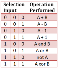
A5) ALU’s comprise the combinational logic that implements logic operations such as AND, OR, NOT gate and arithmetic operations, such as Adder, Subtractor.
Functionally, the operation of typical ALU is represented as shown in diagram below,
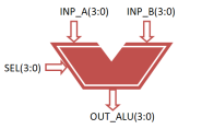
Figure. Functional Description of 4-bit Arithmetic Logic Unit
Controlled by the three function select inputs (sel 2 to 0), ALU can perform all the 8 possible logic operations
VHDL Code for 4-bit ALU
library IEEE; | |
use IEEE.STD_LOGIC_1164.ALL; | |
use IEEE.NUMERIC_STD.ALL; | |
| |
entity alu is | |
Port ( inp_a : in signed(3 downto 0); | |
inp_b : in signed(3 downto 0); | |
sel : in STD_LOGIC_VECTOR (2 downto 0); | |
out_alu : out signed(3 downto 0)); | |
end alu; | |
| |
architecture Behavioral of alu is | |
Begin | |
process(inp_a, inp_b, sel) | |
Begin | |
case sel is | |
when "000" => | |
out_alu<= inp_a + inp_b; – addition | |
when "001" => | |
out_alu<= inp_a - inp_b; – subtraction | |
when "010" => | |
out_alu<= inp_a - 1; – sub 1 | |
when "011" => | |
out_alu<= inp_a + 1; – add 1 | |
when "100" => | |
out_alu<= inp_a and inp_b; – AND gate | |
when "101" => | |
out_alu<= inp_a or inp_b; – OR gate | |
when "110" => | |
out_alu<= not inp_a ; – NOT gate | |
when "111" => | |
out_alu<= inp_a xor inp_b; – XOR gate | |
when others => | |
NULL; | |
end case; | |
| |
end process; | |
| |
end Behavioral; |
Testbench VHDL Code for 4-Bit ALU
LIBRARY ieee; | |
USE ieee.std_logic_1164.ALL; | |
USE ieee.numeric_std.ALL; | |
| |
ENTITY Tb_alu IS | |
END Tb_alu; | |
| |
ARCHITECTURE behavior OF Tb_alu IS | |
| |
– Component Declaration for the Unit Under Test (UUT) | |
| |
COMPONENT alu | |
PORT( | |
inp_a : IN signed(3 downto 0); | |
inp_b : IN signed(3 downto 0); | |
sel : IN std_logic_vector(2 downto 0); | |
out_alu : OUT signed(3 downto 0) | |
); | |
END COMPONENT; | |
| |
| |
– Inputs | |
signal inp_a : signed(3 downto 0) := (others => '0'); |
signal inp_b : signed(3 downto 0) := (others => '0'); |
signal sel : std_logic_vector(2 downto 0) := (others => '0'); | |
| |
– Outputs | |
signal out_alu : signed(3 downto 0); | |
| |
BEGIN | |
| |
– Instantiate the Unit Under Test (UUT) | |
uut: alu PORT MAP ( | |
inp_a =>inp_a, | |
inp_b =>inp_b, | |
sel =>sel, | |
out_alu =>out_alu | |
); | |
| |
– Stimulus process | |
stim_proc: process | |
Begin | |
– hold reset state for 100 ns. | |
wait for 100 ns; | |
| |
– insert stimulus here | |
| |
inp_a<= "1001"; | |
inp_b<= "1111"; | |
| |
sel<= "000"; | |
wait for 100 ns; | |
sel<= "001"; | |
wait for 100 ns; | |
sel<= "010"; | |
wait for 100 ns; | |
sel<= "011"; | |
wait for 100 ns; | |
sel<= "100"; | |
wait for 100 ns; | |
sel<= "101"; | |
wait for 100 ns; | |
sel<= "110"; | |
wait for 100 ns; | |
sel<= "111"; | |
end process; | |
| |
END; | |
Simulation Result for 4-bit ALU
Figure. ALU
Q6) Write a short note on encoder and decoder?
A6) In a 4:2 encoder, the circuit takes 4 bits of data as input. It then codes the data to give an output of two bits.
By behavior, we mean, the response or output of a circuit under the application of a certain set of inputs.
Truth table of a 4:2 encoder
A | B | C | D | Y0 | Y1 |
|
|
|
|
|
|
|
0 | 0 | 0 | 1 | 0 | 0 |
|
|
|
|
|
|
|
0 | 0 | 1 | 0 | 0 | 1 |
|
|
|
|
|
|
|
0 | 1 | 0 | 0 | 1 | 0 |
|
|
|
|
|
|
|
1 | 0 | 0 | 0 | 1 | 1 |
|
|
|
|
|
|
|
The entity-architecture pair. The entity will have the port declaration statements of four input ports and two output ports. This is defined as STD_LOGIC_VECTOR datatype.
library IEEE;
use IEEE.STD_LOGIC_1164.ALL;
use IEEE.STD_LOGIC_ARITH.ALL;
use IEEE.STD_LOGIC_UNSIGNED.ALL;
entity ENCODER_SOURCE is
Port ( I : in STD_LOGIC_VECTOR (3 downto 0);
Y : out STD_LOGIC_VECTOR (1 downto 0));
end ENCODER_SOURCE;
The behavioral code always has a process statement. The sensitivity list variable here would be the input vector I. We begin the architecture first, define the process, and then begin the process. This order is imperative.
architecture Behavioral of ENCODER_SOURCE is
begin
process (I)
begin
The if sequential statement that we use in VHDL is not to be confused with the if or else-if statement that we are accustomed to in the C programming language. The syntax is a bit different here.
if I = "0001" then Y <= "00";
elsif I = "0010" then Y <= "01";
elsif I = "0100" then Y <= "10";
else Y <= "11";
Towards the end, you need to close the begin statements, as well as the if statement.
end if;
end process;
end Behavioral;
Q7) Explain full adder?
A7)
Library ieee;
use ieee.std_logic_1164.all;
entity full_adder is port(a,b,c:in bit; sum,carry:out bit);
end full_adder;
architecture data of full_adder is
begin
sum<= a xor b xor c;
carry <= ((a and b) or (b and c) or (a and c));
end data;

Figure. Full Adder
Q8) Explain multiplexer?
A8)
Library ieee;
use ieee.std_logic_1164.all;
entity mux is
port(S1,S0,D0,D1,D2,D3:in bit; Y:out bit);
end mux;
architecture data of mux is
begin
Y<= (not S0 and not S1 and D0) or
(S0 and not S1 and D1) or
(not S0 and S1 and D2) or
(S0 and S1 and D3);
end data;
Waveforms
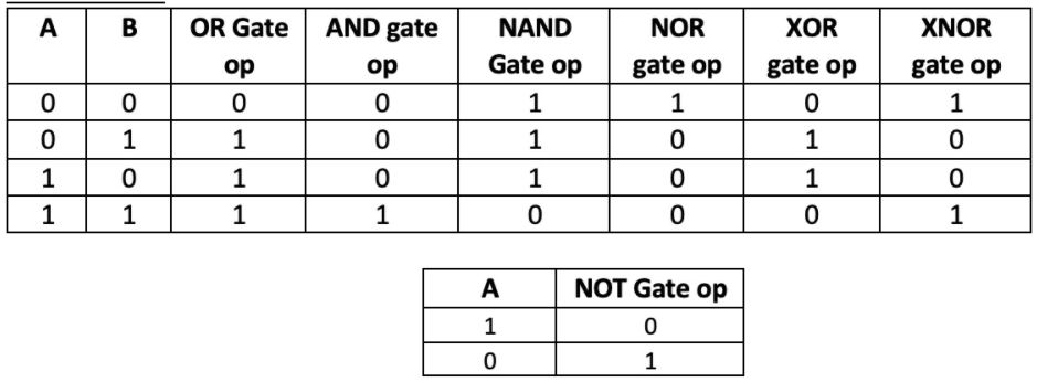
Figure. Multiplexer
Q9) Explain tristate drivers?
A9)
library IEEE;
use IEEE.std_logic_1164.all;
entity TS_DRVR is
port ( IN_BITS : in BIT_VECTOR ( 15 downto 0 );
OE : in BIT := '1';
OUT_BITS : out STD_LOGIC_VECTOR (15 downto 0) );
end TS_DRVR;
architecture SIMPLE of TS_DRVR is
begin
process ( OE, IN_BITS ) -- if OE or input data
-- change, may change output
begin
if OE = '0' then -- if OE asserted, then
OUT_BITS <= To_StdLogicVector ( IN_BITS );
else -- otherwise
OUT_BITS <= "ZZZZZZZZZZZZZZZZ"; -- tri-state output
end if;
end process;
end SIMPLE;
Q10) Explain PIPO?
A10)
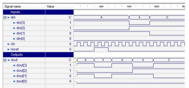
Figure. 4 bit PIPO
library IEEE;
use IEEE.STD_LOGIC_1164.all;
entity pipo_behavior is
port(
clk : in STD_LOGIC;
reset : in STD_LOGIC;
din : in STD_LOGIC_VECTOR(3 downto 0);
dout : out STD_LOGIC_VECTOR(3 downto 0)
);
end pipo_behavior;
architecture pipo_behavior_arc of pipo_behavior is
begin
pipo : process (clk,din,reset) is
begin
if (reset='1') then
dout<= "0000";
elsif (rising_edge (clk)) then
dout<= din;
end if;
end process pipo;
end pipo_behavior_arc;
