ENGINEERING GRAPHICS
UNIT 1
- Define scales and its necessity?
Scales
A scale is defined as the ratio of the linear dimensions of the object as represented in a drawing to the actual dimensions of the same.
Necessity
- Drawings drawn with the same size as the objects are called full sized drawing.
- It is not convenient, always, to draw drawings of the object to its actual size. e.g. Buildings, Heavy machines, Bridges, Watches, Electronic devices etc.
- Hence scales are used to prepare drawing at
Full size
Reduced size
Enlarged size
Types of Scale
2. Explain engineers scale?
Engineers Scale :
The relation between the dimension on the drawing and the actual dimension of the object is mentioned numerically (like 10 mm = 15 m).
Mechanical Engineers Scale:
These are divided and numbered in such a way that fractions of inches represent inches. The most common ranges are 1/8, 1/4, 1/2, and 1 in. To the inch. These scales are known as the size scales because the reduced size also represents the ratio of size, as for example one-eighth size.
Mechanical engineer's scales are almost always "full divided"; that is, the smallest divisions run throughout the entire length.
They are generally graduated with the marked divisions numbered from right to left, as well as from left to right, as shown in Figure Mechanical engineer's scales are used mostly for drawings of machine parts and small structures where the drawing size is more than one-eighth the size of the actual object.
Civil Engineers Scale:
These are divided into decimals with divisions ranging from 10, 20, 30, 40, 50, 60, and 80 to the inch. Such a scale is usually full divided and is sometimes numbered both from left to right and right to leave. Civil engineer's scales are most used for plotting and drawing maps, although they are convenient for any work where divisions of the inch, in tenths is required.
3. Explain graphical scale?
Graphical Scale:
Scale is drawn on the drawing itself. This takes care of the shrinkage of the engineer’s scale when the drawing becomes old.
Types of Graphical Scale
- Plain Scale
- Diagonal Scale
- Vernier Scale
- Comparative scale
4. Define plain scale?
Plain Scale
- A plain scale consists of a line divided into suitable number of equal units. The first unit is subdivided into smaller parts.
- The zero should be placed at the end of the 1st main unit.
- From the zero mark, the units should be numbered to the right and the sub-divisions to the left.
- The units and the subdivisions should be labeled clearly.
5. Define Diagonal scale?
Diagonal Scale
- Through Diagonal scale, measurements can be up to second decimal (e.g. 4.35).
- Diagonal scales are used to measure distances in a unit and its immediate two subdivisions; e.g. Dm, cm & mm, or yard, foot & inch.
- Diagonal scale can measure more accurately than the plain scale.
6. Define vernier scale?
Vernier Scales
- Similar to Diagonal scale, Vernier scale is used for measuring up to second decimal.
- A Vernier scale consists of
(i) a primary scale and
(ii) a vernier.
- The primary scale is a plain scale fully divided into minor divisions.
- The graduations on the vernier are derived from those on the Least count (LC) is the minimum distance that can be measured.
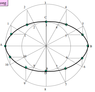
7. Draw ellipse by concentric circle method. Take major axis 100 mm and minor axis 70 mm long.
Steps:
1. Draw both axes as perpendicular bisectors of each other & name their ends as shown.
2. Taking their intersecting point as a center, draw two concentric circles considering both as respective diameters.
3. Divide both circles in 12 equal parts & name as shown.
4. From all points of outer circle draw vertical lines downwards and upwards respectively.
5.From all points of inner circle draw horizontal lines to intersect those vertical lines.
6. Mark all intersecting points properly as those are the points on ellipse.
7. Join all these points along with the ends of both axes in smooth possible curve. It is required ellipse.

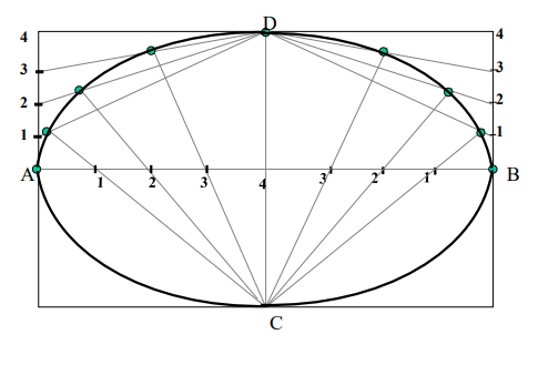
8. Draw ellipse by Rectangle method. Take major axis 100 mm and minor axis 70 mm long.
Steps:
1 Draw a rectangle taking major and minor axes as sides.
2. In this rectangle draw both axes as perpendicular bisectors of each other..
3. For construction, select upper left part of rectangle. Divide vertical small side and horizontal long side into same number of equal parts.( here divided in four parts)
4. Name those as shown..
5. Now join all vertical points 1,2,3,4, to the upper end of minor axis. And all horizontal points i.e.1,2,3,4 to the lower end of minor axis.
6. Then extend C-1 line upto D-1 and mark that point. Similarly extend C-2, C-3, C-4 lines up to D-2, D-3, & D-4 lines.
7. Mark all these points properly and join all along with ends A and D in smooth possible curve. Do similar construction in right side part.along with lower half of the rectangle.
8. Join all points in smooth curve. It is required ellipse.

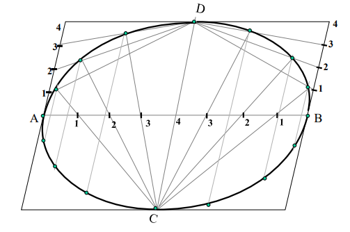
9. Draw ellipse by Oblong method. Draw a parallelogram of 100 mm and 70 mm long sides with included angle of 750.Inscribe Ellipse in it.
(STEPS ARE SIMILAR TO THE PREVIOUS CASE (RECTANGLE METHOD) ONLY IN PLACE OF RECTANGLE, HERE IS A PARALLELOGRAM)
