Unit - 3
Dielectric Properties of Matter & Electromagnetic Induction
Q1) If the relative permeability and relative permittivity of the medium is 1.0 and 2.25, respectively. Find the speed of the electromagnetic wave in this medium.
A1)
Given data


Q2) Given E = 10 sin (t-y) ay V/m, in free space, determine D, B and H.
A2)
E = 10 sin (t-y) ay, V/m
D =0E,
0= 8.854 x 10⁻¹² F/m
D = 100sin (t-y) ay, C/m2
Second Maxwell’s equation is
x E = -B
That is,

Or

As Ey= 10 sin (t-z) V/m
 = 0
= 0
Now,x E becomes
x E = -  ax
ax
= 10 cos (t-z) ax
= - 


Q3) If the electric field strength, E of an electromagnetic wave in free space is given by
E = 2 cos (t -  ) ay V/m,
Find the magnetic field, H
A3)
We have
B/t =-x E

Or


Thus

Also


Q4) For a long solenoid the magnetic field strength within the solenoid is given by the equation B=5.0t T, where t is time in seconds. If the induced electric field outside the solenoid is 11 V/m a distance 2.0 m from the axis of the solenoid, find the radius of the solenoid.
A4)
Given
When there is a changing magnetic field through a coil, it causes an induced emf in the coil, which is based on the Faraday's law of electromagnetic induction. Further, the induced emf is related to the induced electric field along the circumference of the coil.
Magnetic field inside the solenoid, B =5.0×t T
Induced electric field at radial distance (from the axis of solenoid) r = 2.0 m is E =11 V/m
Radius (R) of solenoid =?
The induced electric field at the radial distance r from the axis of the solenoid is expressed as:
E×(2πr) =
E×(2πr) =
E×(2×r) =R2
E×(2×r) = R2
11×(2×2) =R2×5
R= 2.966  3.0 m
3.0 m
Q5) A coil has 1000 turns and 500 cm2 as it's area. The plane of the coil is placed at right angles to a magnetic induction field of 2×10⁻⁵ Wb/m2. The coil is rotated through 1800 in 0.2 seconds. What is the average emf induced in the coil (in milli volts)?
A5)
The induced emf will be given by
emf=
=
=
=
=10×10−3V=10 mV
Q6) In a uniform magnetic field of induction B, a wire in the form of semicircle of radius r rotates about the diameter of the circle with angular velocity ω. If the total resistance of the circuit is R, then find the mean power generated per period of rotation.
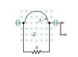
A6)


Power: 
Mean power 

Q7) Discuss Faraday’s law of electromagnetic induction?
A7)
Faraday’s law of electromagnetic induction (referred to as Faraday’s law) is a basic law of electromagnetism predicting how a magnetic field will interact with an electric circuit to produce an electromotive force (EMF). This phenomenon is known as electromagnetic induction.
Faraday’s law states that a current will be induced in a conductor which is exposed to a changing magnetic field. Lenz’s law of electromagnetic induction states that the direction of this induced current will be such that the magnetic field created by the induced current opposes the initial changing magnetic field which produced it. The direction of this current flow can be determined using Fleming’s right-hand rule.
Let us understand Faraday’s law by faraday‘s experiment.
FARADAY’S EXPERIMENT
In this experiment, Faraday takes a magnet and a coil and connects a galvanometer across the coil. At starting, the magnet is at rest, so there is no deflection in the galvanometer i.e. the needle of the galvanometer is at the center or zero position. When the magnet is moved towards the coil, the needle of the galvanometer deflects in one direction.
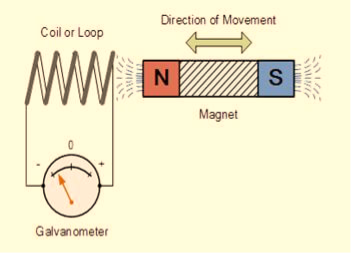
Figure: Faraday’s law of electromagnetic induction
When the magnet is held stationary at that position, the needle of galvanometer returns to zero position. Now when the magnet moves away from the coil, there is some deflection in the needle but opposite direction, and again when the magnet becomes stationary, at that point respect to the coil, the needle of the galvanometer returns to the zero position.
Similarly, if the magnet is held stationary and the coil moves away, and towards the magnet, the galvanometer similarly shows deflection. It is also seen that the faster the change in the magnetic field, the greater will be the induced EMF or voltage in the coil.
Let us take a look at the following table. This table is showing the observation of faraday’s experiment.
Position of magnet | Deflection in galvanometer |
Magnet at rest | No deflection in the galvanometer |
Magnet moves towards the coil | Deflection in galvanometer in one direction |
Magnet is held stationary at same position (near the coil) | No deflection in the galvanometer |
Magnet moves away from the coil | Deflection in galvanometer but in the opposite direction |
Magnet is held stationary at the same position (away from the coil) | No deflection in the galvanometer |
Conclusion
From this experiment, Faraday concluded that whenever there is relative motion between a conductor and a magnetic field, the flux linkage with a coil changes and this change in flux induces a voltage across a coil.
Michael Faraday formulated two laws on the basis of the above experiments. These laws are called Faraday’s laws of electromagnetic induction.
Faraday’s First Law
Any change in the magnetic field of a coil of wire will cause an emf to be induced in the coil. This emf induced is called induced emf and if the conductor circuit is closed, the current will also circulate through the circuit and this current is called induced current.
Method to change the magnetic field:
- By moving a magnet towards or away from the coil
- By moving the coil into or out of the magnetic field
- By changing the area of a coil placed in the magnetic field
- By rotating the coil relative to the magnet
Faraday’s Second Law
It states that the magnitude of emf induced in the coil is equal to the rate of change of flux that linkages with the coil. The flux linkage of the coil is the product of the number of turns in the coil and flux associated with the coil.
According to Faraday’s law of electromagnetic induction, the rate of change of flux linkage is equal to induced emf.
 ………..(9)
Considering Lenz’s Law
Where:
- Flux Φ in Wb = B.A
- B = magnetic field strength
- A = area of the coil
Factors on which induced emf depend
- By increasing the number of turns in the coil i.e. N, from the formulae derived above it is easily seen that if the number of turns in a coil is increased, the induced emf also gets increased.
- By increasing magnetic field strength i.e. B surrounding the coil- Mathematically, if magnetic field increases, flux increases and if flux increases emf induced will also get increased. Theoretically, if the coil is passed through a stronger magnetic field, there will be more lines of force for the coil to cut and hence there will be more emf induced.
- By increasing the speed of the relative motion between the coil and the magnet – If the relative speed between the coil and magnet is increased from its previous value, the coil will cut the lines of flux at a faster rate, so more induced emf would be produced.
Q8) Give Physical Significance of Maxwell’s equation?
A8)
Physical significance of Maxwell’s Ist equation
∇·E = ρ/ε0
According to this total electric flux through any closed surface is 1/0 times the total charge enclosed by the closed surfaces, representing Gauss's law of electrostatics, As this does not depend on time, it is a steady state equation. Here for positive , divergence of electric field is positive and for negative divergence is negative. It indicates that is scalar quantity.
Physical significance of Maxwell’s 2nd equation
∇·B = 0
It represents Gauss law of magnetostatic as ∇·B = 0 resulting that isolated magnetic poles or magnetic monopoles cannot exist as they appear only in pairs and there is no source or sink for magnetic lines of forces. It is also independent of time i.e. steady state equation.
Physical significance of Maxwell’s 3rd equation
∇×E = −∂B/∂t
It shows that with time varying magnetic flux, electric field is produced in accordance with Faraday is law of electromagnetic induction. This is a time dependent equation.
Physical significance of Maxwell’s 4th equation
∇×H = J + ∂D/∂t
This is a time dependent equation which represents the modified differential form of Ampere's circuital law according to which magnetic field is produced due to combined effect of conduction current density and displacement current density.
Q9) Discuss Maxwell’s equations?
A9)
Maxwell equations are of fundamental importance since they describe the whole of classical electromagnetic phenomena.
Maxwell's Equations are a set of 4 complicated equations that describe the world of electromagnetics. These equations describe how electric and magnetic fields propagate, interact, and how they are influenced by objects.
Maxwell was one of the first to determine the speed of propagation of electromagnetic (EM) waves was the same as the speed of light - and hence to conclude that EM waves and visible light were really the same thing.
These equations are rules the universe uses to govern the behaviour of electric and magnetic fields. A flow of electric current will produce a magnetic field. If the current flow varies with time (as in any wave or periodic signal), the magnetic field will also give rise to an electric field. Maxwell's Equations shows that separated charge (positive and negative) gives rise to an electric field - and if this is varying in time as well will give rise to a propagating electric field, further giving rise to a propagating magnetic field.
From a classical perspective, light can be described as waves of electromagnetic radiation. As such, Maxwell equations are very useful to illustrate a number of the characteristics of light including polarization.
We are just to stating these equations without derivation. Since our goal is simply to apply them, the usual approach will be followed.
Maxwell’s first equation (Gauss' Law for Electric Fields)
Gauss' Law is the first of Maxwell's Equations which dictates how the Electric Field behaves around electric charges. Gauss' Law can be written in terms of the Electric Flux Density and the Electric Charge Density as:
∇·E = ρ/ε0
0r
∇·D = ρ
Hence, Gauss' law is a mathematical statement that the total Electric Flux exiting any volume is equal to the total charge inside. Hence, if the volume in question has no charge within it, the net flow of Electric Flux out of that region is zero. If there is positive charge within a volume, then there exists a positive amount of Electric Flux exiting any volume that surrounds the charge. If there is negative charge within a volume, then there exists a negative amount of Electric Flux exiting (i.e. the Electric Flux enters the volume).
Maxwell’s second equation (Faraday's Law)
Faraday figured out that a changing Magnetic Flux within a circuit (or closed loop of wire) produced an induced EMF, or voltage within the circuit. Maxwell gives his second equation from this.
Faraday's Law tells us that a magnetic field that is changing in time will give rise to a circulating E-field. This means we have two ways of generating E-fields - from Electric Charges (or flowing electric charge, current) or from a magnetic field that is changing.
∇×E = −∂B/∂t (2)
Maxwell’s third equation (Ampere's Law)
Ampere's Law tells us that a flowing electric current gives rise to a magnetic field that circles the wire. In addition to this, it also says that an Electric Field that is changing in time gives rise to a magnetic field that encircles the E-field - this is the Displacement Current term that Maxwell himself introduced.
This means there are 2 ways to generate a solenoidal (circulating) H-field - a flowing electric current or a changing Electric Field. Both give rise to the same phenomenon.
The modified form of Ampere's Law s given by Maxwell’s third equation
∇×H = J + ∂D/∂t
Maxwell’s four equation (Gauss' Magnetism law)
We know that Gauss' Law for Electric Fields states that the divergence of the Electric Flux Density D is equal to the volume electric charge density. But the second equation, Gauss' Magnetism law states that the divergence of the Magnetic Flux Density (B) is zero.
Why? Why isn't the divergence of B equal to the magnetic charge density?
Well - it is. But it just so happens that no one has ever found magnetic charge - not in a laboratory or on the street or on the subway. And therefore, until this hypothetical magnetic charge is found, we set the right side of Gauss' Law for Magnetic Fields to zero:
∇·B = 0
Now, you may have played with magnets when you were little, and these magnetic objects attracted other magnets similar to how electric charges repel or attract like electric charges. However, there is something special about these magnets - they always have a positive and negative end. This means every magnetic object is a magnetic dipole, with a north and South Pole. No matter how many times you break the magnetic in half, it will just form more magnetic dipoles. Gauss' Law for Magnetism states that magnetic monopoles do not exist - or at least we haven't found them yet.
Maxwell’s four equations are given by
∇·E = ρ/ε0 (1)
∇×E = −∂B/∂t (2)
∇×H = J + ∂D/∂t (3)
∇·B = 0 (4)
These equations illustrate the unique coexistence in nature of the electric field and the magnetic field. The first two equations give the value of the given flux through a closed surface, and the second two equations give the value of a line integral around a loop. In this notation,
∇=(∂/∂x, ∂/∂y, ∂/∂z)
E is the electric vector
B is the magnetic induction
ρ is the electric charge density
j is the electric current density
ε0 is the permittivity of free space
c is the speed of light.
In addition to Maxwell equations, the following identities are useful:
J = σE (5)
D = εE (6)
B = μH (7)
Here,
D is the electric displacement
H is the magnetic vector
σ is the specific conductivity
ε is the dielectric constant (or permittivity)
μ is the magnetic permeability
Q10) Discuss in brief the B-H curve?
A10)
Magnetic Hysteresis
The lag or delay of a magnetic material known commonly as Magnetic Hysteresis relates to the magnetization properties of a material by which it first becomes magnetized and then de-magnetized.
The set of magnetization curves, M above represents an example of the relationship between B and H for soft-iron and steel cores but every type of core material will have its own set of magnetic hysteresis curves. You may notice that the flux density increases in proportion to the field strength until it reaches a certain value where it cannot increase any more becoming almost level and constant as the field strength continues to increase.
This is because there is a limit to the amount of flux density that can be generated by the core as all the domains in the iron are perfectly aligned. Any further increase will not affect the value of M, and the point on the graph where the flux density reaches its limit is called Magnetic Saturation also known as Saturation of the Core and in our simple example above the saturation point of the steel, the curve begins at about 3000 ampere-turns per metre.
As the magnetic field strength, (H) increases these molecular magnets become more and more aligned until they reach perfect alignment producing maximum flux density, and an increase in the magnetic field strength due to an increase in the electrical current flowing through the coil will have little or no effect.
Retentivity
Let’s assume that we have an electromagnetic coil with a high field strength due to the current flowing through it and that the ferromagnetic core material has reached its saturation point, maximum flux density. If we now open a switch and remove the magnetizing current flowing through the coil we would expect the magnetic field around the coil to disappear as the magnetic flux reduced to zero.
However, the magnetic flux does not completely disappear as the electromagnetic core material still retains some of its magnetism even when the current has stopped flowing in the coil. This ability for a coil to retain some of its magnetism within the core after the magnetization process has stopped is called Retentivity or remanence, while the amount of flux density remaining in the core is called Residual Magnetism, BR.
The reason for this that some of the tiny molecular magnets do not return to a completely random pattern and still point in the direction of the original magnetizing field giving them a sort of “memory”. Some ferromagnetic materials have a high retentivity (magnetically hard) making them excellent for producing permanent magnets.
While other ferromagnetic materials have low retentivity (magnetically soft) making them ideal for use in electromagnets, solenoids, or relays. One way to reduce this residual flux density to zero is by reversing the direction of the current flowing through the coil, thereby making the value of H, the magnetic field strength negative. This effect is called a Coercive Force, HC.
If this reverse current is increased further the flux density will also increase in the reverse direction until the ferromagnetic core reaches saturation again but in the reverse direction from before. Reducing the magnetizing current, i once again to zero will produce a similar amount of residual magnetism but in the reverse direction.
Then by constantly changing the direction of the magnetizing current through the coil from a positive direction to a negative direction, as would be the case in an AC supply, a Magnetic Hysteresis loop of the ferromagnetic core can be produced.
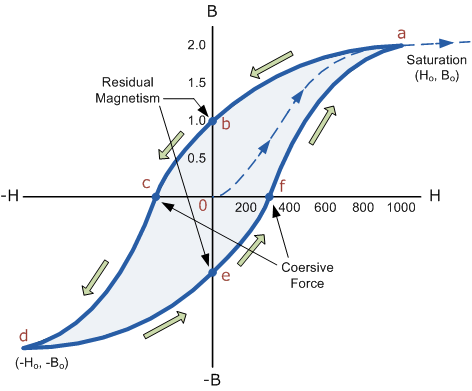
Figure: B-H Curve
The B-H Curve or Magnetic Hysteresis loop above shows the behaviour of a ferromagnetic core graphically as the relationship between B and H is non-linear.
Starting with an unmagnetized core both B and H will be at zero, point 0 on the magnetization curve.
If the magnetization current, i is increased in a positive direction to some value the magnetic field strength H increases linearly with i and the flux density B will also increase as shown by the curve from point 0 to point a as it heads towards saturation.
Now if the magnetizing current in the coil is reduced to zero, the magnetic field circulating around the core also reduces to zero. However, the coils magnetic flux will not reach zero due to the residual magnetism present within the core and this is shown on the curve from point a to point b.
To reduce the flux density at point b to zero we need to reverse the current flowing through the coil. The magnetising force which must be applied to null the residual flux density is called a “Coercive Force”. This coercive force reverses the magnetic field re-arranging the molecular magnets until the core becomes unmagnetised at point c.
An increase in this reverse current causes the core to be magnetised in the opposite direction and increasing this magnetisation current further will cause the core to reach its saturation point but in the opposite direction, point d on the curve.
This point is symmetrical to point b. If the magnetising current is reduced again to zero the residual magnetism present in the core will be equal to the previous value but in reverse at point e.
Again reversing the magnetising current flowing through the coil this time into a positive direction will cause the magnetic flux to reach zero, point f on the curve and as before increasing the magnetisation current further in a positive direction will cause the core to reach saturation at point a.
Then the B-H curve follows the path of a-b-c-d-e-f-a as the magnetising current flowing through the coil alternates between a positive and negative value such as the cycle of an AC voltage. This path is called a B-H Curve or Magnetic Hysteresis Loop.
The effect of magnetic hysteresis shows that the magnetisation process of a ferromagnetic core and therefore the flux density depends on which part of the curve the ferromagnetic core is magnetised on as this depends upon the circuits past history giving the core a form of “memory”. Then ferromagnetic materials have memory because they remain magnetised after the external magnetic field has been removed.
However, soft ferromagnetic materials such as iron or silicon steel have very narrow magnetic hysteresis loops resulting in very small amounts of residual magnetism making them ideal for use in relays, solenoids, and transformers as they can be easily magnetised and demagnetised.
Since a coercive force must be applied to overcome this residual magnetism, work must be done in closing the hysteresis loop with the energy being used being dissipated as heat in the magnetic material. This heat is known as hysteresis loss, the amount of loss depends on the material’s value of coercive force.
By adding additives to the iron metal such as silicon, materials with a very small coercive force can be made that have a very narrow hysteresis loop. Materials with narrow hysteresis loops are easily magnetised and demagnetised and known as soft magnetic materials.
Q11) Draw B-H Curve for Soft and Hard Materials?
A11)
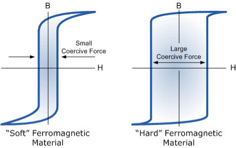
Figure: Magnetic Hysteresis Loops for Soft and Hard Materials
The shape of the hysteresis loop depends upon the nature of the iron or steel used and in the case of iron which is subjected to massive reversals of magnetism, for example, transformer cores, the B-H hysteresis loop must be as small as possible.
Q12) What are the applications of faraday’s law?
A12)
Faraday law is one of the most basic and important laws of electromagnetism. This law finds its application in most of the electrical machines, industries, and the medical field, etc.
- Power transformers function based on Faraday’s law
- The basic working principle of the electrical generator is Faraday’s law of mutual induction.
- The Induction cooker is the fastest way of cooking. It also works on the principle of mutual induction. When current flows through the coil of copper wire placed below a cooking container, it produces a changing magnetic field. This alternating or changing magnetic field induces an emf and hence the current in the conductive container, and we know that the flow of current always produces heat in it.
- Electromagnetic Flow Meter is used to measure the velocity of certain fluids. When a magnetic field is applied to an electrically insulated pipe in which conducting fluids are flowing, then according to Faraday’s law, an electromotive force is induced in it. This induced emf is proportional to the velocity of fluid flowing.
- From bases of Electromagnetic theory, Faraday’s idea lines of force is used in well-known Maxwell’s equations. According to Faraday’s law, change in magnetic field gives rise to change in electric field and the converse of this is used in Maxwell’s equations.
- It is also used in musical instruments like an electric guitar, electric violin, etc.
Q13) Find the capacitance for Parallel plate capacitor filled with dielectric?
A13)
Capacity of a parallel plate condenser which is partially filled with a dielectric medium- By the distance between the plates is d and in between the plates there is a dielectric medium of thick-ness t and dielectric constant K. If each plate is given a charge +q then surface charge.
σ=q/A
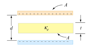
Figure: Parallel plate Capacitor filled with dielectric
Where A is the surface area of the plates. If the distance between the plates in negligible in comparison to their area then the intensity of electric field in the area filled with air between the plates.
Eo= σ / εo
Electric field intensity within the dielectric medium E= σ/ Kεo
By the definition of potential difference, the potential difference between the plates.
V= Work done in moving a unit charge from one plate (negative) to another (positive) plate.
= Work done in moving a unit charge a distance (d−t) in air and distance t in dielectric medium
V=Eo×(d−t)+Et
On substituting the values of Eo and E


Hence capacity of the condenser


Q14) Find the capacitance for Spherical capacitor filled with dielectric?
A14)
Spherical capacitor filled with dielectric
Consider there are two spheres, the inner and outer sphere as shown in figure. The inner radius of sphere is “a” and outer radius of sphere is “b”.
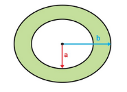
Figure: Spherical capacitor
Now if a charge of Q coulomb is supplied to the outer conductor shell of the capacitor where r is the radius of the sphere. Then the potential or voltage built at the surface of the capacitor is given by
 …… (1)
If we ground the outer surface of the capacitor and supply a positive charge of Q coulombs to the inner spheres.
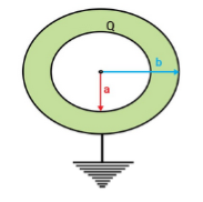
Figure: Spherical capacitor
Then a charge –Q is induced at the inner surface of the outer sphere and a charge +Q is induced at the outer surface of the outer sphere will be sent to the ground. Now the surface potential at the outer sphere due to its own charge

And the surface potential at the inner sphere due to its own charge

Thus, the potential difference between two spheres is


On arranging the equation, we get the ratio of Q and V which is equal to the capacitance.


When we assume that there is no air between them means the vacuum is present then the equation of capacitance is given by

Now we assume that there is no vacuum between them. And we inserted dielectric material between them. Permittivity of the medium is 
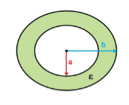
Figure: Spherical capacitor
Now the capacitance of the sphere with dielectric material in it is given as

We know that Dielectric constant is also called Relative Permittivity Dielectric Constant is expressed by Greek letter kappa ‘κ’. It is dimensionless quantity.
It is mathematically expressed as:
K =κ = 
Where,
- κ is the dielectric constant
- 𝜺 is the permittivity of the substance
- 𝜺0 is the permittivity of the free space
Using it we get


Which is the required value of spherical capacitance when dielectric material is inserted in it.
Q15) Find the capacitance for cylindrical capacitor filled with dielectric?
A15)
Cylindrical capacitor filled with dielectric
Consider there are two cylinders, the inner and outer cylinders as shown in figure. The length of both the cylinders is L. Also inner radius of cylinder is “a” and outer radius of cylinder is “b”.
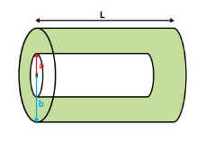
Figure: Cylindrical capacitor filled with dielectric
Consider charge per meter length of the cable on the outer surface the inner cylinder is +Q and on the inner surface the outer cylinder is –Q.

Figure: Cylindrical capacitor filled with dielectric
The surface area of the coaxial cylinder of radius x meters and length 1 meter is

Electric field at a point x meters away from the center of the inner cylinder is

Thus potential difference developed between the plates or cylinder in the parallel plate capacitors V is given by

By putting the value of E


Thus capacitance is given by


Thus capacitance is given by

Insert the dielectric material. Now we assume that there is no vacuum between them. And we inserted dielectric material between them. Permittivity of the medium is  . Thus capacitance is given by

We know that Dielectric constant is also called Relative Permittivity Dielectric Constant is expressed by Greek letter kappa ‘κ’. It is dimensionless quantity.
It is mathematically expressed as:
K =κ = 
Where,
- κ is the dielectric constant
- 𝜺 is the permittivity of the substance
- 𝜺0 is the permittivity of the free space
Using it we get

Which is the required value of cylindrical capacitance when dielectric material is inserted in it.
Q16) Discuss the relation between E, P and D?
A16)
The permittivity εo of free space is 8.854×10⁻¹² farads/meter, where
 =εo
=εo  .
.
The permittivity ε of any material deviates from εo for free space if applied electric fields induce electric dipoles in the medium; such dipoles alter the applied electric field seen by neighbouring atoms.
Electric fields generally distort atoms because  pulls on positively charged nuclei (f=q
 [N]) and repels the surrounding negatively charged electron clouds. The resulting small offset d of each atomic nucleus of charge +q relative to the center of its associated electron cloud produces a tiny electric dipole in each atom, as suggested in Figure: (a).
In addition, most asymmetric molecules are permanently polarized, such as H2O or NH3, and can rotate within fluids or gases to align with an applied field. Whether the dipole moments are induced, or permanent and free to rotate, the result is a complete or partial alignment of dipole moments as suggested in Figure: (b).
These polarization charges generally cancel inside the medium, as suggested in Figure: (b), but the immobile atomic dipoles on the outside surfaces of the medium are not fully cancelled and therefore contribute the surface polarization charge ρsp

Figure: Polarized media
Figure (c) suggests how two charged plates might provide an electric field  that polarizes a dielectric slab having permittivity ε > εo. The electric field
  is the same in vacuum as it is inside the dielectric (assuming no air gaps) because the path integral of
  from plate to plate equals their voltage difference V in both cases. The electric displacement vector
  e =ε
e =ε  and therefore differs.] We associate the difference between
  o =εo
o =εo (vacuum) and
  ε=ε
ε=ε (dielectric) with the electric polarization vector P , where:
 = ε
= ε =εo
=εo  +
+ = εo
= εo  (1+
(1+ ) (8)
) (8)
The polarization vector  is defined by (8) and is normally parallel to
  in the same direction, as shown in Figure: 11(c); it points from the negative surface polarization charge to the positive surface polarization charge (unlike
  , which points from positive charges to negative ones).
As suggested in (8),  = εo
= εo  ,
,
Where χ is defined as the dimensionless susceptibility of the dielectric. Because nuclei are bound rather tightly to their electron clouds, χ is generally less than 3 for most atoms, although some molecules and crystals, particularly in fluid form, can exhibit much higher values.
Electric displacement, also known as dielectric displacement and usually denoted by D, is a vector field in a non-conducting medium, a dielectric.
In a dielectric material, the presence of an electric field E causes the bound positive and negative charges in the material to slightly separate, inducing a local electric dipole moment. The electric displacement field "D" is defined as
D= 𝜺0E+P
D =
Electric displacement
E = External electric field in which the dielectric is placed
𝜺0 = the permittivity of the free space
P = Polarization Density
In S.I. System, Unit of Electric displacement is C/m2.
D =  E+P
E+P
D=  E and P =
  eE
eE
Relation between dielectric constant and susceptibility
Electric displacement, also known as dielectric displacement and usually denoted by D, is a vector field in a non-conducting medium, a dielectric.
In a dielectric material, the presence of an electric field E causes the bound positive and negative charges in the material to slightly separate, inducing a local electric dipole moment. The electric displacement field "D" is defined as
D= 𝜺0E+P
D =
Electric displacement
E = External electric field in which the dielectric is placed
𝜺0 = the permittivity of the free space
P = Polarization Density
In S.I. System, Unit of Electric displacement is C/m2.
D =  E+P
E+P
D=  E and P =
  eE
eE
Substituting these values in eq (1), we get
 E =
E =  E+
E+ eE
eE
 =
=  +
+ e
e
 = 1 +
= 1 + 
But
κ =  = Dielectric constant
κ = 1 + 
Clearly values of κ for all dielectric is greater than one, and for empty space  e=0 and κ =1.
Q17) Discuss ferromagnetic material?
A17)
A ferromagnetic material is made up of smaller regions, called ferromagnetic domain. Within each domain, the magnetic moments are spontaneously aligned in a direction. This alignment is caused by strong interaction arising from electron spin which depends on the inter-atomic distance. Each domain has net magnetisation in a direction. However the direction of magnetisation varies from domain to domain and thus net magnetisation of the specimen is zero.
In the presence of external magnetic field, two processes take place
1. The domains having magnetic moments parallel to the field grow in size
2. The other domains (not parallel to field) are rotated so that they are aligned with the field.
As a result of these mechanisms, there is a strong net magnetisation of the material in the direction of the applied field
This magnetic domain theory for ferromagnetic was first proposed by Pierre-Ernest Weiss in 1906. The microscopic ordering of electron spins characteristic of ferromagnetic materials leads to the formation of regions of magnetic alignment called domains.
The magnetic moments of atoms dictate the magnetic properties of a material. In ferromagnetic materials, long-range alignments of magnetic moments, called domains, contain magnetic moments that all point in the same direction.
However, if material were to have all of its magnetic moments pointed in the same direction, this would create a very large external magnetic field. This field is not energetically minimizing as it stores large amounts of magnetostatic energy in the field.
Thus, for the system to minimize its internal energy, it must minimize the external field produced. To do this, the material creates different domains within itself to redirect the magnetic field. The regions in-between these domains are known as domain walls.
Interactions of a material's exchange interaction, magnetocrystalline anisotropy, and minimization of external magnetic field determine the domain structure of a material.
The magnetisation within the domain is saturated and will always lie in the easy direction of magnetisation when there is no externally applied field. The direction of the domain alignment across a large volume of material is more or less random and hence the magnetisation of a specimen can be zero.
Magnetic domains exist to reduce the energy of the system. A uniformly magnetized specimen as shown in figure 12a) has large magnetostatic energy associated with it. This is the result of the presence of magnetic free poles at the surface of the specimen generating a demagnetizing field, Hd. From the convention adopted for the definition of the magnetic moment for a magnetic dipole the magnetisation within the specimen points from the south pole to the north pole, while the direction of the magnetic field points from north to south. Therefore, the demagnetizing field is in opposition to the magnetisation of the specimen. The magnitude of Hd is dependent on the geometry and magnetisation of the specimen.
In general, if the sample has a high length to diameter ratio (and is magnetized in the long axis) then the demagnetizing field and the magnetostatic energy will be low.
The break-up of the magnetisation into two domains as illustrated in figure (b) reduces the magnetostatic energy by half. In fact, if the magnet breaks down into N domains then the magnetostatic energy is reduced by a factor of 1/N, hence figure (c) has a quarter of the magnetostatic energy of figure (a). Figure (d) shows a closure domain structure where the magnetostatic energy is zero, however, this is only possible for materials that do not have a strong uniaxial anisotropy, and the neighbouring domains do not have to be at 180º to each other.

Figure: Schematic illustration of the break-up of magnetisation into domains: (a) single domain; (b) two domains; (c) four domains; (d) closure domains.
The introduction of a domain raises the overall energy of the system, therefore the division into domains only continues while the reduction in magnetostatic energy is greater than the energy required to form the domain wall.
The energy associated with a domain wall is proportional to its area. The schematic representation of the domain wall, shown in figure, illustrates that the dipole moments of the atoms within the wall are not pointing in the easy direction of magnetisation and hence are in a higher energy state.
Also, the atomic dipoles within the wall are not at 180º to each other and so the exchange energy is also raised within the wall. Therefore, the domain wall energy is an intrinsic property of material depending on the degree of magneto crystalline anisotropy and the strength of the exchange interaction between neighbouring atoms. The thickness of the wall will also vary in relation to these parameters, as a strong magneto crystalline anisotropy will favour a narrow wall, whereas a strong exchange interaction will favour a wider wall.
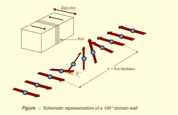
Figure: Schematic representation of a 180o domain wall
Minimum energy can therefore be achieved with a specific number of domains within a specimen. This number of domains will depend on the size and shape of the sample (which will affect the magnetostatic energy) and the intrinsic magnetic properties of the material (which will affect the magnetostatic energy and the domain wall energy).
The main implication of the domains is that there is already a high degree of magnetization in ferromagnetic materials within individual domains, but that in the absence of external magnetic fields those domains are randomly oriented. A modest applied magnetic field can cause a larger degree of alignment of the magnetic moments with the external field, giving a large multiplication of the applied field.
These illustrations of domains are conceptual only and not meant to give an accurate scale of the size or shape of domains.
The microscopic evidence about magnetization indicates that the net magnetization of ferromagnetic materials in response to an external magnetic field may occur more by the growth of the domains parallel to the applied field at the expense of other domains rather than the reorientation of the domains themselves as implied in the sketch.
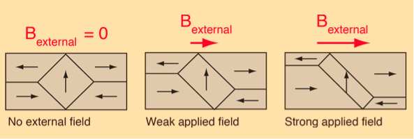
Figure: Domain Alignment
The internal magnetic fields which come from the long-range ordering of the electron spins are much stronger, sometimes hundreds of times stronger, than the external magnetic fields required to produce these changes in domain alignment.
Q18) Write down expression for electric displacement?
A18)
Besides the bound charges due to polarization, a dielectric material may also contain some extra charges which just happen to be there. For a lack of a better term, such extra charges are called free charges, just to contrast them from the bound charged due to polarization. Anyway, the net macroscopic electric field does not care for the origin of the electric charges or how we call them but only
 net(r) =
 free(r) +
  bound(r);
  net(r) =
  free(r) +
  bound(r); ………(1)
In particular, the Gauss Law in differential form says
 0
0 .E(r) =
  net(r) +
  net
net  (coordinate ⟂ surface) + more
  function terms due to linear and point charges ………(2)
For simplicity, let's ignore for a moment the surface, line, and point charges and focus on just the volume charge density. This gives us
 0
0 .E(r) =
  net(r) =
  free(r) +
  bound(r) =
  free(r) −∇ ·P
Which we may rewrite as
∇.(ε0E+P) =  free ………(3)
In light of this formula, the combination
D(r) =ε0E(r) +P(r) ………(4)
Called the electric displacement field obeys the Gauss Law involving only the free charges but not the bound charges,
∇.D(r) =  free
free
Q19) Explain Electric Polarization?
A19)
Electric Polarization
Electronic polarization refers to the separation of centre of positive charge and centre of negative charge in a material.This separation is caused by high electric field.
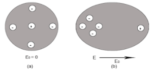
Figure: (a) shows thecharge distribution of an atom in absence of electric field while figure (b) show the charge distribution in presence of external electrical field.
Let us consider a single atom of atomic number Z. +e coulomb is the charge of each proton in the nucleus and -e coulomb is the charge of each electron surrounds the nucleus. All electrons in the atom form a spherical cloud of negative charge surrounds the positively charged nucleus. The charge of nucleus is +Ze coulombs and charge of the negative cloud of electrons is -Ze coulombs.
Let us also assume that the negative charge of the electrons cloud is homogeneously distributed on a sphere of radius R. In the absence of external electric field, the center of this sphere and center of nucleus of the atom coincide.
When an external electric field E is applied to the atom. Because of this external electric field the nucleus of the atom is shifted towards negative intensity of the field and the electron cloud is shifted towards the positive intensity of the field.
As due to influence of external electric field the center of nucleus and center of electrons cloud are separated, there will be an attractive force between them according to Coulomb’s law.
Let us suppose x is distance of separation between positive charge nucleus and electron cloud.
Also Nucleus is considered as point charge. Hence, the electrostatic force acting on the nucleus =+EZe …….(1)
As we know nucleus has been shifted from the center of electrons cloud by a distance x.
By using Gauss’s theorem
The force is only due to electron cloud acting upon nucleus would only be due to the portion of the cloud enclosed by the sphere of radius x. Portion outside the sphere of radius x does not apply any force on the nucleus.
Volume of the sphere of radius x = (4/3)πx3 and
Volume of the sphere of radius R = (4/3)πR3
Now total negative charge of the electron cloud is -Ze …..(2)
Hence, the quantity of negative charge enclosed by the sphere of radius x is,
[-Ze/(4/3)πR3] * (4/3)πx3 = -Ze (x3/ R3) ……..(3)
According to coulomb’s law = q1q2 /4 πR2
Here it becomes charge on electrons q1=-Ze (x3/ R3)
Charge on nucleus q2= Ze
So coulomb’s force = {-Ze (x3/ R3) * Ze}/4πƐox2 = Z2e2x/4πƐo R3 ……(4)
Note- magnitude is taken into account. Neglect negative sign.
i.e. At equilibrium Electrostatic force = Coulomb force.
EZe = Z2e2x/4πƐoR3 ……..(5)
Upon simplify
x = {4πƐoR3/Ze} E
Now dipole moment = either charge * separation between charges i.e. x
= Ze *{4πƐoR3/Ze} E
= 4πƐoR3E
Polarization is number of dipole moment per unit volume. Let us suppose N is the number of dipoles per unit volume so
Pe=4πƐoR3EN
So it is clear that polarization depends upon radius of atom or volume of atom and number of atoms present per unit volume.
Q20) What are the differences between polar and non-polar molecules? Also discuss the effect of electric field on dielectric?
A20)
The response of a dielectric material depends on the nature of its molecules. The molecules of a dielectric is of two types
- Polar molecules
- Non-polar molecules
Polar Molecules: Polar Molecules are those in which centre of gravity of positive and negative charge does not coincide with each other. This is because they all are asymmetric in shape. Examples: H2O, CO2, NO2 etc. The molecule of material are composed of two or more different atoms, which have permanently dipole moment because the centre of gravity of positive charge and negative charge does not coincide with each other but separated by a finite (small) distance.
Normally this type of molecular dipole in polar dielectric are randomly oriented such that their net dipole moment becomes zero and material act as a neutral material.
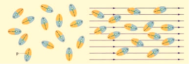
Figure: Effect of electric felid on dielectric
Polar Molecules are those type of dielectric in which the possibilities that the positive and negative molecules will coincide with each other is null or zero.
Non-Polar Molecule: Non-polar molecules are those in which centre of gravity of positive charge and negative charge coincide with each other. The molecule has zero dipole moment as they all are symmetric in shape. Examples: O2, N2, H2 etc.
Dielectrics materials in which the molecule's center of gravity of positive charge and negative charge coincide with each other and so the molecules are electrically neutral and hence zero dipole moment.
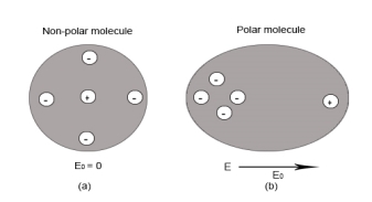
Figure: Polar molecules & Non polar molecules
Response of Dielectric to External Electric Field
In case of Polar Molecules -When the electric field is not present, it causes the electric dipole moment of these molecules in a random direction. This is why the average dipole moment is zero. If the external electric field is present, the molecules align themselves in the direction electric field and resulted in having dipole moment.
In case of Non-Polar Molecules – As we know nonpolar molecule has zero dipole moment. In spite of zero dipole, when a dielectric nonpolar material is placed in an electric field. The positive and the negative charges in a nonpolar molecule experience forces in opposite directions. This force causes the separation between the charges and hence nonpolar molecule experiences induced dipole moment.
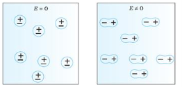

Figure (a) (left) Non Polar Molecule Figure 18 (b) (right) Polar Molecule
Q21) What do you mean by Electric susceptibility, dielectric constant and Dielectric Strength?
A21)
Electric susceptibility
Susceptibility is the extent to which a given material gets polarised when it is kept in an electric field.
If the material gets polarised more, it will set up an internal field which opposes the external field which will then reduce the total electric flux through that material. Therefore, electric susceptibility affects the electric permittivity of the medium.
Greater the level of polarisation, lower will be the electric permitivity
For most linear dielectric materials, the polarization P is directly proportional to the average electric field strength E so that the ratio of the two, P/E, is a constant that expresses an intrinsic property of the material.
The electric susceptibility, χe, in the centimetre-gram-second (cgs) system, is defined by this ratio; that is,
χe = P/E.
In the metre-kilogram-second (mks) system, electric susceptibility is defined slightly differently by including the constant permittivity of a vacuum, ε0, in the expression; that is,
χe = P/(ε0E).
In both systems the electric susceptibility is always a dimensionless positive number. Because of the slight difference in definition, the value of the electric susceptibility of a given material in the mks system is 4π times its value in the cgs system.
Susceptibility of polar dielectric depends upon the temperature whereas Susceptibility of non-polar dielectric is independent of the temperature.
Dielectric constant
Dielectric constant it is a quantity measuring the ability of a substance to store electrical energy in an electric field.
Or
The ratio of the permittivity of the substance to the permittivity of the free space
Dielectric constant is also called Relative Permittivity Dielectric Constant is expressed by Greek letter kappa ‘κ’. It is dimensionless quantity.
It is mathematically expressed as:
κ = 
Where,
- κ is the dielectric constant
- 𝜺 is the permittivity of the substance
- 𝜺0 is the permittivity of the free space
Dielectric constant in terms of capacitance
Dielectric constant is equal to the ratio of the capacitance of a capacitor filled with the given material to the capacitance of an identical capacitor in a vacuum without the dielectric material.
If C is the value of the capacitance of a capacitor filled with a given dielectric and C0 is the capacitance of an identical capacitor in a vacuum, the dielectric constant κ, is simply expressed as
κ = 
Dielectric Strength
It is defined as the maximum electric field which the material can sustain without breaking down.
When a high electric field is applied to the dielectric, the outer electrons get detached from their parent atoms. The dielectric then behaves as a conductor. In other words every dielectric starts conducting when if an external field is applied to it. This value of electric field depends on the nature of material of dielectric and is called dielectric strength.