Unit - 1
Integrated Circuits and Digital Circuits
Q1) What are Active Components? Give its Example.
A1)
Active components are devices that can amplify and produce power from an electric signal. An oscillator, transistor, or integrated circuit will be present in any typical active component. In devices, an active component serves as an alternating current circuit. This aids the device's ability to increase power and voltage. Because it is fueled by electricity, this component can carry out its functions. All active components require a source of energy, which is typically derived from a DC circuit.
Example of Active Components
Because of their nature, active components rely on external sources to function. They have the ability to supplement and provide power to the circuit. The many sorts of active components are listed below.
Transistors:
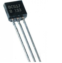
Transistors magnify current by taking in a low voltage of energy and producing a higher output voltage. This semiconductor device is a crucial component that can be found in a variety of circuit designs. BC547, 2N2222, and BC557 are the most popular and widely used transistors. Depending on the device's planning, they can be individualistic or packaged together. The most often used Transistors have a wide range of functions, including voltage regulation, amplification, signal adjustment, and so on.
Silicon Controlled Rectifiers (SCRs):
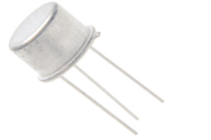
SCRs, or Silicon Controlled Rectifiers, are a form of power electronics switch. Anode, Cathode, and Gate are the three terminals. The switch is open by default, and no current flows between the SCR's anode and cathode terminals. The switch is closed when a tiny current is applied to the gate pin, allowing a considerable amount of current to travel between the Anode and Cathode terminals. The operation of a Thyristor/SCR is similar to that of a BJT (Transistor). The load to be switched is connected between the anode and cathode, and the Thyristor is turned on or off by passing a gate current through the gate pin. 2N2324 and 2N1595 are the most popular and widely used Thyristors.
Q2) Differences between Active and passive components.
A2)
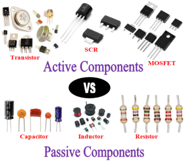
All electronic components can be divided into two categories: active components and passive components. Based on their functional features and functioning, these components are diametrically opposed to one another. We'll learn about the many sorts of active and passive components, as well as the differences between active and passive devices, in this post. But, before understanding how different they are from each other, it is important to understand what each component means and how they work, so let's get started with active components.
Now that we have understood about the Active and Passive devices and its types, let us do a comparison between active and passive components based on certain parameters as defined below
1) Source of energy – Active components necessitate an additional energy source. The operation of passive components does not necessitate the use of an additional source of energy. A resistor is self-contained and does not require a certain voltage to function.
2) Energy: Active components produce energy in the form of voltage or current, whilst passive components, such as a capacitor, store energy in the form of an electric field and an inductor, store energy in the form of a magnetic field.
3) Linearity: Active components are non-linear, whereas passive components are linear. According to Ohms Law, the voltage drop across a passive component like a resistor will be linear to its resistance value. The output of a transistor or other active component, on the other hand, will have a non-linear amplification factor.
4) Power gain: Active components can provide power growth, however passive components lack the potential to magnify power.
5) Controlling the current: As the name implies, an active component may easily influence current flow. A passive component cannot do the same task.
6) External source: Active components, as previously said, require an additional source to control and sustain their activities, whereas passive components do not require an external source.
Q3) What is an Integrated Circuit (IC)?
A3)
Previously, circuits were huge and cumbersome, consisting of circuit components such as resistors, capacitors, inductors, transistors, diodes, and other components coupled with copper wires. This aspect limited the circuits' application to large machinery. With these large circuits, it was impossible to make small and compact appliances. Furthermore, they were not completely shockproof or dependable.
Necessity, as they say, is the mother of all inventions. As a result, smaller circuits with more power and safety were needed to be integrated into gadgets. Three American scientists invented transistors, which greatly simplified things, but the creation of integrated circuits completely transformed the face of electronics technology.
The integrated circuit is a basic concept in electronics that draws on other key concepts we've already covered in class. As a result, read the following articles for a quick reference:
- Electric Circuits
- Resistors
- Transistors
- Diodes
- Capacitors
Definition of Integrated Chip
An integrated circuit, often known as an IC, is a compact semiconductor chip that contains a whole circuit. When compared to ordinary circuits, which are built up of distinct circuit components, it is extremely compact. Monolithic integrated circuits are the most frequent type of IC.
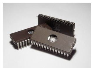
An Integrated Circuit (IC) is a microchip that contains thousands or hundreds of electrical components such as resistors, capacitors, and transistors. Oscillators, amplifiers, microprocessors, timers, and computer memory are all examples of ICs.
Q4) What is PELCO® Mica Sheets, Grade V5 And Give Its Description.
A4)
Various sizes available, presenting many fresh, clean surfaces for such EM applications as carbon filming and particle spraying. Thickness, 0.23mm - 0.3mm (0.009" - 0.12").
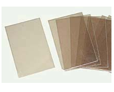
Rod # | Description | Unit | Price | Order / Quote | |
53-15 | PELCO® Mica Sheets, Grade V5, 15 x 15mm (0.59 x 0.59") | Pkg/10 | $7.80 |
| |
53-25 | PELCO® Mica Sheets, Grade V5, 25 x 25mm (1 x 1") | Pkg/10 | 10.60 |
| |
54 | PELCO® Mica Sheets, Grade V5, 10 x 40mm (0.39 x 1.57") | Pkg/100 | 27.80 |
| |
53 | PELCO® Mica Sheets, Grade V5, 25 x 75mm (1 x 3"), | Pkg/20 | 15.20 |
| |
52 | PELCO® Mica Sheets, Grade V5, 50 x 75mm (2 x 3"), | Pkg/10 | 16.80 |
|
Q5) Explain the Properties of Wafer Mounting Film.
A5)
Properties:
- Orientation: 1 for 100> "111> for 3" Resistance: 1-30 Ohms, 2", 4", and 6" wafers
- (Boron) Type P: (1 primary flat)
- There is no SiO2 top coating.
- The thickness of a wafer is measured in millimetres.
- a single "= 10 - 12 millimetres (254 - 304 metres)
- a second "= 9 - 13 millimetres (230 - 330 metres)
- a third "= 13.6 – 18.5 millimetres (345 – 470 metres)
- (4) "= 18.7 – 22.6 millimetres (475 – 575 metres)
- (6) "= 23.6 – 25.2 millimetres (600 – 690 metres)
- 2 nm roughness
- TTV: 20m TTV: 20m TTV: 20m TTV: 20m TTV: 20m TTV: 20
- One side of the wafer is polished.
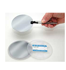
Q6) Write short note on PELCO® Gold Coated Silicon Wafers.
A6)
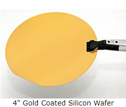
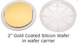
2" and 4" gold-coated silicon wafers for SEM or AFM supports, nanotechnology, and biotechnology. Both Cr and Au are evaporated on silicon wafers using a vacuum evaporation technique, with chromium serving as an adhesive layer between the glass and the gold. The gold surface is not atomically flat, but it does have nm-sized blemishes. A wafer carrier is used to pack and ship the wafers. At 175° C, the Au coating should be stable; above that temperature, delamination may occur.
Wafer specifications:
- Thickness 4”, 460-530m, 2”, 254-301m, 111> orientation, P-type
- The thickness of the chromium adhesion layer is 5nm.
- 50nm (5nm) gold layer thickness
- 2" or 4" in diameter
|
Q7) Difference between Chip and Wafer in Electronics
A7)
A chip, also known as an integrated circuit, is a single-unit assembly of electronic components, whereas a wafer refers to thin slices of silicon that are utilised in the fabrication of integrated circuits since the integrated circuits are implanted in these wafers.
An integrated circuit, often known as a chip, is a compact electronic device that consists of a collection of circuits, paths, transistors, and other components that work together to perform a single task or a series of operations. Most modern electronic gadgets, such as microprocessors, audio and video equipment, and automobiles, rely on chips. The wafer contains the integrated circuit. Electronic components such as transistors are found on a chip. The term "microchip" is abbreviated to "chip." They're in charge of the logic circuitry.
A silicon wafer is used to make a chip. Chips come in a variety of shapes and sizes. Microprocessors are another name for CPU chips. Chips can be categorised into the following categories based on their electronic components:-
SSI (small-scale integration): each chip has up to 100 electronic components.
MSI (medium-scale integration): a chip with between 100 and 3,000 electrical components.
LSI (large-scale integration): a chip with between 3,000 and 100,000 electronic components.
VLSI (very large-scale integration): a chip with 100,000 to one million electronic components.
ULSI (ultra large-scale integration): a chip with over one million electronic components.
A wafer is also known as a slice or substrate in electronics. It's a sliver of cheese.
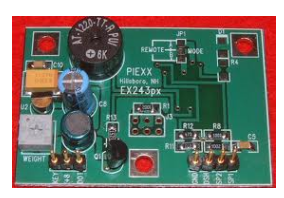
This slice is made of semiconductor material and is used to make integrated circuits. It serves as a foundation for the creation of an integrated circuit. These small slices are thought to be the brains of electronic devices. Diffusion and deposition of various chemicals are used to build microcircuits on wafers. In comparison to prior iterations, the ever-growing electronics industry always strives to create thinner chips that are more efficient and cost less.
Q8) Give the Advantages of Monolithic ICs.
A8)
1. The size is miniature. The IC is much smaller since the active and passive components are combined on a silicon chip utilising a fabrication process. It might be at least a thousand times smaller than a discrete circuit.
2. When compared to a discrete circuit, the IC's weight is reduced due to its tiny size.
3. The cost of manufacturing hundreds of ICs is relatively inexpensive, and it takes very little time. Producing hundreds of discrete circuits on a PCB for the same logic, on the other hand, takes longer and costs more.
4. The soldered joints on the PCB will be less reliable. Because there are no soldered joints and fewer interconnections in ICs, this problem is avoided, making them extremely dependable.
5. Because ICs are tiny, they consume less power and lose less power.
6. In discrete circuitry, a single defective transistor can cause the entire circuit to fail. This transistor requires desoldering and replacement. It's tough to figure out which part of the system has failed. Because replacing a complete IC is inexpensive, this problem can be avoided in an IC.
7. Higher operating speed due to the absence of parasitic capacitance.
8. Because the ICs are mass-produced, temperature coefficients and other properties will be very similar.
9. Improved functional performance due to the ability to fabricate more complicated circuits with better features.
10. All integrated circuits are evaluated for operating ranges in extremely cold and extremely hot temperatures.
11. Since all of the components in an IC are built very close to one another, they are ideal for small signal operation because there will be no stray electrical pickup.
12. There will be no exterior projections because all of the components are created inside the chip.
Monolithic integrated circuits have been used to perform a wide range of operations since their creation. Amplifiers, voltage regulators, crowbars, AM receivers, TV circuits, and computer circuits are all examples of commercially available ICs of this sort.
Q9) What are Digital ICs?
A9)
The acronym IC stands for "integrated circuit," and it refers to any semiconductor-based chip that contains an integrated set of digital circuitry. Digital integrated circuits are available in a variety of shapes and sizes; the table below lists the IC types that are often utilised in diverse applications.
Microcomputers are integrated circuits (ICs) that do many sorts of processing.
Recollection
Data-storage integrated circuits
Logic ICs of the Standard Type
ICs assembled in various configurations to fulfil specific functions
Logic ICs Made to Order
Original dedicated circuitry created by or for a specific user's demands
A standard logic IC is a single, tiny integrated package that has basic components and common logic circuit functionality. These integrated circuits are essential parts of logic circuits. This type of IC will be the subject of today's presentation on digital ICs.
Q10) Explain the Significance of Fan-Out.
A10)
When connecting ordinary logic ICs to a specific output, extreme caution must be exercised to avoid connecting too many ICs to a single output. The output current of TTL ICs restricts the number of IC connections. The greatest number of ICs that an output can connect to is referred to as fan-out.
Because TTL ICs are primarily made up of bipolar transistors, current is required to perform switching. The ratio of a TTL IC's output current to the current utilised by each input is known as fan-out (see Fig. 3). If fan-out is surpassed, there's a chance the output won't be able to keep up with the output logic levels.
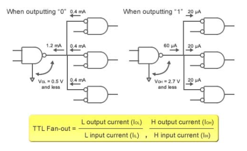
Figure: TTL IC Fan-out
Fan-out cannot be measured by looking at currents in CMOS ICs since very little current goes to the input terminals. Instead, load capacity determines fan-out. (Take a look at Fig.) The propagation delay is used to determine the load capabilities listed on CMOS IC data sheets. If the load capacity is exceeded, the propagation delay may become so long that it causes a malfunction.
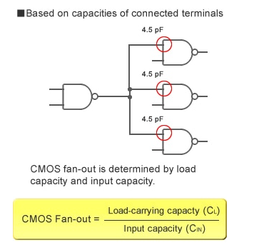
Figure: CMOS IC Fan-out
Q11) What is Binary Number System?
A11)
One of the four types of number systems is a binary number system. Binary numbers are represented by simply two symbols or digits in computer applications, namely 0 (zero) and 1 (one) (one). The base-2 numeral system is used to express the binary numbers. A binary number, for example, is (101)2. In this approach, each digit is referred to as a bit. Here's where you can learn about the number system.
In computer architecture, a number system is a means to represent numbers. There are four different kinds of number systems, for example:
1. The binary system of numbers (base 2)
2. System of octal numbers (base 8)
3. The decimal system (base 10)
4. The scheme of hexadecimal numbers (base 16).
A binary number is described as a number that is stated in the binary system or base 2 numeral system, according to digital technology and mathematics. It uses two distinct symbols to represent numerical values: 1 (one) and 0 (zero) (zero). The positional notation with 2 as a radix is known as the base-2 system.
Because of its direct application in electronic circuits utilising logic gates, the binary system is used internally by practically all modern computers and computer-based devices. A bit is a unit of measurement for each digit.
Q12) How to Calculate Binary Numbers?
A12)
For example, the number to be operated is 1235.
Thousands | Hundreds | Tens | Ones |
1 | 2 | 3 | 5 |
This indicates,
1235 = 1 × 1000 + 2 × 100 + 3 × 10 + 5 × 1
Given,
1000 | = 103 = 10 × 10 × 10 |
100 | = 102 = 10 × 10 |
10 | = 101 = 10 |
1 | = 100 (any value to the exponent zero is one) |
The above table can be described as,
Thousands | Hundreds | Tens | Ones |
103 | 102 | 101 | 100 |
1 | 2 | 3 | 5 |
Hence,
1235 = 1 × 1000 + 2 × 100 + 3 × 10 + 5 × 1
= 1 × 10³ + 2 × 10² + 3 × 101 + 5 × 100
The decimal number system is based on the base 10 system, which uses the digits 0 through 9 to represent numbers. The digits 0-1 represent numbers in the binary system, which uses base 2, and the base is known as radix. To put it another way, the above table can also be displayed in the following way.
Thousands | Hundreds | Tens | Ones | |
Decimal | 103 | 102 | 101 | 100 |
Binary | 23 | 22 | 21 | 20 |
In base 10, we place the digits in columns 100, 101, and so forth. When a value greater than 9 is required, such as in the form of 10(n+1), you must first add 1 to column 101 before adding 10 to column 100.
In base 2, we position the digits in columns 20, 21, and so on. To place a value greater than 1 in 2n, multiply it by 2(n+1). To add 3 to column 20, for example, you must first add 1 to column 21.
Q13) Explain Binary to Decimal Formula.
A13)
N=bnqn+bn−1qn−2+…..+b2q2+b1q1+b0q0+b−1q−1+b−2q−2
Where,
N is decimal equivalent,
b is the digit,
q is the base value that starts from the most significant digit order qn to least significant order q-1, q-2, …..
To convert binary to decimal the following chart is used and binary is noted as per the given decimal number.
Binary | 0 | 1 | 10 | 11 | 100 | 101 | 110 | 111 | 1000 | 1001 | 1010 | 1011 | 1100 | 1101 | 1110 | 1111 |
Decimal | 0 | 1 | 2 | 3 | 4 | 5 | 6 | 7 | 8 | 9 | 10 | 11 | 12 | 13 | 14 | 15 |
If you use a binary number string, for example, you should include the subscript “2” to represent a base 2 number, making the binary number 102. Similarly, if it were a conventional decimal number, it would be expressed as 1010 with the subscript "10" to represent a base 10.
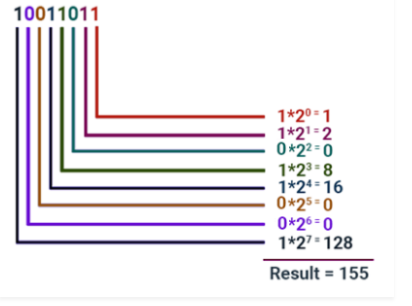
The process of converting binary to decimal is straightforward and can be done as follows:
Let's say we wish to convert the 8-bit value 10011101 to a decimal value. We can do it using the formula table below:
128 | 64 | 32 | 16 | 8 | 4 | 2 | 1 |
1 | 0 | 0 | 1 | 1 | 1 | 0 | 1 |
To convert, pick a value from the top row and place it where a 1 appears below it, then add the values together.
As a consequence, you will get 157.
Q14) What is Binary Coded Decimal?
A14)
Another method for converting decimal values to binary equivalents is Binary Coded Decimal, or BCD.
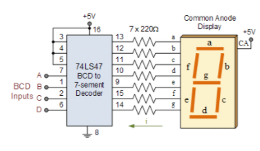
There are many different binary codes used in digital and electronic circuits, each with its own specialised function, as we've seen in this Binary Numbers part of lessons.
We need a mechanism to translate decimal numbers into a binary (base-2) environment that computers and digital electrical devices can understand because we live in a decimal (base-10) world. Binary coded decimal code allows us to do so.
An n-bit binary code is a set of “n” bits that can assume up to 2n different combinations of 1s and 0s, as we've seen before. The advantage of the Binary Coded Decimal system is that, like Hexadecimal, each decimal digit is represented by a group of four binary digits or bits. So we'll need a 4-bit binary code to represent the ten decimal digits (0–9).
Binary-coded decimal is not the same thing as hexadecimal. Binary coded decimal numerals stop at 9 binary 10012, although a 4-bit hexadecimal number is acceptable up to F16 meaning binary 11112 (decimal 15). Although 16 numbers (24) can be represented with four binary digits, the six binary code combinations 1010 (decimal 10), 1011 (decimal 11), 1100 (decimal 12), 1101 (decimal 13), 1110 (decimal 14), and 1111 (decimal 15) are classified as forbidden numbers in the BCD numbering system and cannot be used.
The fundamental benefit of binary-coded decimal is that it is simple to convert between decimal (base-10) and binary (base-2) forms. However, because the states between 1010 (decimal 10) and 1111 (decimal 15) are not used in BCD code, it is inefficient. Nonetheless, binary coded decimal has a wide range of uses, particularly in the context of digital displays.
A decimal number is divided into four bits in the BCD numbering system for each decimal digit inside the number. Each decimal digit is represented with a weighted binary value that translates the number directly. Each displayed decimal digit is represented by a 4-bit group, which ranges from 0000 for a zero to 1001 for a nine.
Q15) Give the Summary Of BCD.
A15)
As we've seen, Binary Coded Decimal, or BCD, is essentially a 4-bit binary code representation of a decimal digit, with each decimal digit replaced with its binary equivalent in the integer and fractional sections. The ten decimal digits of 0 to 9 are represented by four bits in BCD Code.
For example, if we wanted to display decimal numbers from 0-to-9, we'd need 4 data bits (a nibble), decimal numbers from 0-to-99, we'd need 8 bits (one byte), decimal numbers from 0-to-999, we'd need 12 bits, and so on. Packed BCD is defined as the use of a single byte (8 bits) to store or display two BCD digits, allowing a byte to hold a BCD number in the range of 00 – 99.
A weighted 8421 BCD code is a standard binary coded decimal code in which the weights of the individual bits are represented by 8, 4, 2, and 1, starting with the most significant bit (MSB) and progressing to the least significant bit (LSB) (LSB). The individual places of the bits in a BCD code are weighted as follows: 23 = 8, 22 = 4, 21 = 2, 20 = 1.
The fundamental advantage of the Binary Coded Decimal system over the pure binary system is that it is a faster and more efficient approach for converting decimal numbers to binary values. However, the BCD code is inefficient since many of the 4-bit stages (10-to-16) are not used, whereas decimal displays are useful.
Q16) Short note on Octal Number System.
A16)
Another form of computer and digital numbering system that employs the Base-8 standard is the Octal Number System.
The Octal Numbering System is identical to the previous hexadecimal numbering system in theory, except that a binary number is broken into groups of only three bits in Octal, with each group or set of bits having a different value between 000 (0) to 111 ( 4+2+1 = 7 ).
As a result, octal numbers have only "8" digits (0, 1, 2, 3, 4, 5, 6, 7) and are thus a Base-8 numbering system, with q equal to "8."
The basic characteristics of an Octal Numbering System are that there are only eight unique counting digits from 0 to 7, each with a weight or value of only eight starting with the least important bit (LSB). Because it worked in counts of eight, inputs and outputs were in counts of eight, a byte at a time, octal numbers and the octal numbering system were particularly popular in the early days of computers for counting inputs and outputs.
The subscript 8 is used to identify a number represented in octal since the basis of an Octal Numbers system is 8 (base-8), which also denotes the number of distinct numbers employed in the system. An octal number, for example, is written as 2378.
The "octal number system," like the hexadecimal system, allows huge binary numbers to be converted into more compact and smaller groups. However, the octal numbering system is no longer as popular as the hexadecimal numbering system, and it has all but vanished as a digital base number system.
Q17) What is Two Input Logic Gates.
A17)
There are 16 logic gates for two logical inputs. Table gives the logical symbol, behaviour in symbolic logic, name, and remarks for the 16 logic gates.
The ones with the names NAND, NOR, AND, OR, and XOR are the most well-known. These, as well as AND and OR gates with either input negated, logic 0 and logic 1 (which aren't truly logic gates), and certain non-binary gates, are all listed in Table.
| Output when AB is |
|
|
|
| |||
Gate # | 00 | 01 | 10 | 11 | Symbolic Logical Description | Symbol | Name/Description | Note |
0 | 0 | 0 | 0 | 0 | 0 |  | Always zero | Not really a gate |
1 | 0 | 0 | 0 | 1 | A & B |  | AND |
|
2 | 0 | 0 | 1 | 0 | A & ~B |  | A and Not B | Universal |
3 | 0 | 0 | 1 | 1 | A |  | A | Not BInary |
4 | 0 | 1 | 0 | 0 | ~A & B |  | B and Not A | Universal |
5 | 0 | 1 | 0 | 1 | B |  | B | Not Binary |
6 | 0 | 1 | 1 | 0 | (A & ~B) | (~A & B) |  | XOR | Also Not Equals Function |
7 | 0 | 1 | 1 | 1 | A | B |  | OR |
|
8 | 1 | 0 | 0 | 0 | ~(A | B) |  | NOR | Universal |
9 | 1 | 0 | 0 | 1 | (A & B) | (~A & ~B) |  | XNOR | Also Equals Function |
10 | 1 | 0 | 1 | 0 | ~B |  | Not B | Not Binary |
11 | 1 | 0 | 1 | 1 | A | ~B |  | A or Not B | Universal |
12 | 1 | 1 | 0 | 0 | ~A |  | Not A | Not Binary |
13 | 1 | 1 | 0 | 1 | ~A | B |  | B or Not A | Unversal |
14 | 1 | 1 | 1 | 0 | ~(A & B) |  | NAND | Universal |
15 | 1 | 1 | 1 | 1 | 1 |  | Always 1 | Not really a gate |
Q18) Write short note on Universal Logic Gates.
A18)
One of the key disadvantages of employing the whole sets of AND, OR, and NOT gates is that we need two (or more) different types of logic gates, AND and NOT, OR and NOT, or all three as shown above, to generate any equivalent logic gate or function. All of the other Boolean functions and gates, on the other hand, may be implemented using just one form of universal logic gate, the NAND (NOT AND) or NOR (NOT OR) gate, minimising the number of various types of logic gates necessary as well as the cost.
The NAND and NOR gates are the complements of the previous AND and OR functions, respectively, and are each a full set of logic in and of themselves, as they can be used to build any other Boolean function or gate. However, because we may build further logic switching functions using just these gates, they are both referred to as a minimal set of gates. As a result, the NAND and NOR gates are known as Universal Logic Gates.
Q19) What are Universal Gates?
A19)
A universal gate is a type of logic gate that can implement any Boolean function without the usage of any additional logic gates. The universal gates are the NOR and NAND gates. This means that using only NOR or NAND gates, you can build any logical Boolean statement.
In reality, this is beneficial because NOR and NAND gates are less expensive and easier to make than other logic gates. It's so common that an AND gate is implemented as a NAND gate followed by an inverter (rather than the other way around)! An OR gate, on the other hand, is usually implemented as a NOR gate followed by an inverter.
Other logical gates, such as AND gates, NOT gates, and OR gates, lack this universality trait. It's worth noting that these three logic gates can implement all of the conceivable Boolean switching functions when used together, but not when used separately. As a result, they are not classified as universal gates like the NOR and NAND logic gates.
Many of the better Arduino starter kits include these ubiquitous NOR and NAND gates if you want to experiment with them as part of an electronics project.
Q20) Give Example of Parity Checker.
A20)
Input: A = “0001”, B = “0010”
Output: 0011
Input: A = “1010”, B = “0101”
Output: 1111
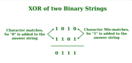
Below is the implementation of the above approach:
● C++
● Java
● Python3
● C#
● Javascript
// C++ Implementation to find the
// XOR of the two Binary Strings
#include<bits/stdc++.h>
Using namespace std;
// Function to find the
// XOR of the two Binary Strings
String xoring(string a, string b, int n){
String ans = "";
// Loop to iterate over the
// Binary Strings
For (int i = 0; i < n; i++)
{
// If the Character matches
If (a[i] == b[i])
Ans += "0";
Else
Ans += "1";
}
Return ans;
}
// Driver Code
Int main()
{
String a = "1010";
String b = "1101";
Int n = a.length();
String c = xoring(a, b, n);
Cout << c << endl;
}
Output:
0111


