Unit - 1
Electric Field and Electric Potential
Q1) Derive a relation for electric field due to a dipole on the axial line?
A1)
Electric field due to an electric dipole at points on the axial line
Consider an electric dipole placed on the x-axis as shown in Figure. A point C is located at a distance of r from the midpoint O of the dipole along the axial line.
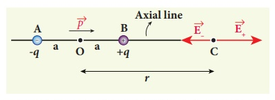
Figure: Electric field of the dipole on the axial line
The electric field at a point C due to +q is
 along BC ………(1)
Since the electric dipole moment vector  is from –q to +q and is directed along BC, the above equation is rewritten as
 ………(2)
Where p ^ is the electric dipole moment unit vector from –q to +q.
The electric field at a point C due to –q is
 ………(3)
Since +q is located closer to the point C than –q,  , is stronger than
  , Therefore, the length of the
  vector is drawn larger than that of
  vector.
The total electric field at point C is calculated using the superposition principle of the electric field.

 ………(4)
 ………(5)
 ………(6)
Note that the total electric field is along  , since +q is closer to C than –q.
The direction of  , is shown in Figure.
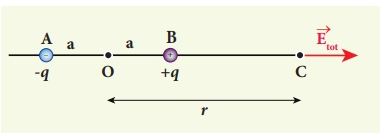
Figure: Total electric field of the dipole on the axial line
If the point C is very far away from the dipole then (r >> a). Under this limit the term ( r2 − a2 )2 ≈ r4 . Substituting this into equation (6), we get

Since 
 ………(7)
If the point C is chosen on the left side of the dipole, the total electric field is still in the direction of  .
.
Q2) Derive a relation for electric field due to a dipole at a point on the equatorial plane? How is this case differing from dipole on axial line?
A2)
Electric field due to an electric dipole at a point on the equatorial plane
Consider a point C at a distance r from the midpoint O of the dipole on the equatorial plane as shown in Figure.
Since the point C is equidistant from +q and –q, the magnitude of the electric fields of +q and –q are the same. The direction of  is along BC and the direction of
  is along CA.
  and
and  are resolved into two components; one component parallel to the dipole axis and the other perpendicular to it. The perpendicular components |
 | sinθ and |
 | sinθ are oppositely directed and cancel each other. The magnitude of the total electric field at point C is the sum of the parallel components of
  + and
+ and  and its direction is along -
 as shown in the Figure.
 ………(8)
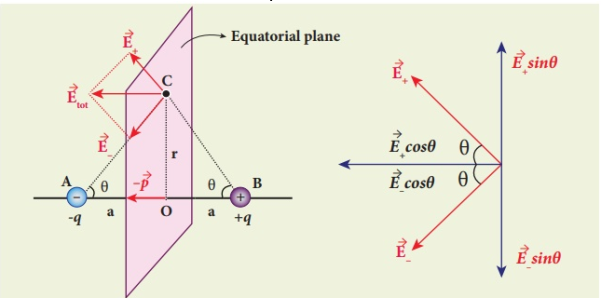
Figure: Electric field of the dipole at a point on the equatorial plane
The magnitudes  + and
+ and  are the same and are given by
 ………(9)
By substituting equation (9) into equation (8), we get


Since 

Since  ………(10)
At very large distances (r>>a), the equation (10) becomes
 ………(11)
Important inferences
(i) From equations (7) and (11), it is inferred that for very large distances, the magnitude of the electric field at points on the dipole axis is twice the magnitude of the electric field at points on the equatorial plane. The direction of the electric field at points on the dipole axis is directed along the direction of dipole moment vector  but at points on the equatorial plane it is directed opposite to the dipole moment vector, that is along -
 .
.
(ii) At very large distances, the electric field due to a dipole varies as 1/r3. Note that for a point charge, the electric field varies as 1/r2. This implies that the electric field due to a dipole at very large distances goes to zero faster than the electric field due to a point charge. The reason for this behaviour is that at very large distance, the two charges appear to be close to each other and neutralize each other.
(iii) The equations (7) and (11) are valid only at very large distances (r>>a). Suppose the distance 2a approaches zero and q approaches infinity such that the product of 2aq = p is finite, then the dipole is called a point dipole. For such point dipoles, equations (7) and (11) are exact and hold true for any r.
Q3) Derive a relation for torque on an electric dipole in a uniform electric field?
A3)
Torque on an electric dipole in a uniform electric field
Consider a dipole with charges +q and –q forming a dipole since they are a distance d away from each other. Let it be placed in a uniform electric field of strength E such that the axis of the dipole forms an angle θ with the electric field.
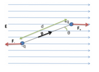
Figure: Electric Dipole in a Uniform Electric Field
The force on the charges is


The components of force perpendicular to the dipole are:


Since the force magnitudes are equal and are separated by a distance d, the torque on the dipole is given by:
Torque (τ) = Force ×Distance Separating Forces
τ=dqEsinθ
Since dipole moment is given by:
p=qd
And the direction of the dipole moment is from the positive to the negative charge, it can see from the above equation that the torque is the cross product of the dipole moment and electric field. Notice that the torque is in the clockwise direction (hence negative) in the above figure. If the direction of Electric Field is positive, Thus,
τ=−pEsinθ
Or,


Q4) Define Gauss’s law?
A4)
Gauss’s law of electrostatics
The law was published posthumously in 1867 as part of a collection of work by the famous German mathematician Carl Friedrich Gauss.
Gauss’s law for the electric field describes the static electric field generated by a distribution of electric charges.
It states that the electric flux through any closed surface is proportional to the total electric charge enclosed by this surface.
Let’s calculate the electric flux through a spherical surface around a positive point charge q, since we already know the electric field in such a situation. Recall that when we place the point charge at the origin of a coordinate system, the electric field at a point P that is at a distance r from the charge at the origin is given by

 is the radial vector from the charge at the origin to the point P. We can use this electric field to find the flux through the spherical surface of radius r, as shown in Figure.
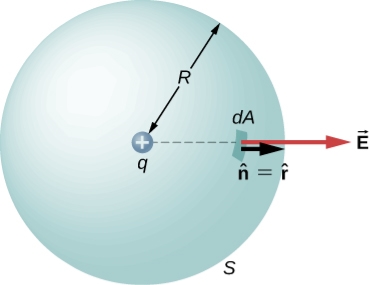
Figure: A closed spherical surface surrounding a point charge q.
Then we apply Φ=∫S  ⋅
⋅ dA
dA
To this system and substitute known values. On the sphere,  and r=R
So for an infinitesimal area dA,


We now find the net flux by integrating this flux over the surface of the sphere

Where the total surface area of the spherical surface is 4πR2. This gives the flux through the closed spherical surface at radius r as
Φ=q/ϵ0
A remarkable fact about this equation is that the flux is independent of the size of the spherical surface. This can be directly attributed to the fact that the electric field of a point charge decreases as 1/r2 with distance, which just cancels the r2 rate of increase of the surface area.
Q5) Draw Electric field lines for positive and negative point charges, two opposite charges, two like charges, and two oppositely charged plates?
A5)
Electric field lines
Figure is a pictorial representation of the electric fields surrounding a positive charge and a negative charge. These lines are called field lines or lines of force.
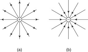
Figure: Electric field lines of (a) positive and (b) negative point charges.
Figure shows the electric fields for opposite charges, similar charges, and oppositely charged plates.
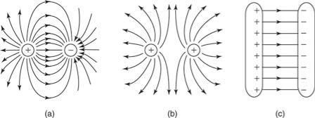
Figure: Electric field lines of (a) two opposite charges, (b) two like charges, and (c) two oppositely charged plates.
Q6) Define Electric flux?
A6)
Electric flux is defined as the number of field lines that pass through a given surface. In Figure, lines of electric flux emerging from a point charge pass through an imaginary spherical surface with the charge at its center.
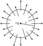
Figure: Electric flux
Q7) Derive an expression for electric potential for uniformly charged rod?
A7)
Electric potential is the work done by an applied force on a unit charge bringing it from infinity to a specific point. The work done is called electric Potential.
Consider a non-conducting rod of length A having a uniform charge density λ. Find the electric potential at P, a perpendicular distance y above the midpoint of the rod.
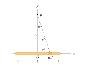
Figure: A non-conducting rod of length l and uniform charge density λ
Consider a differential element of length dx′ which carries a charge dq =λdx′, as shown in Figure. The source element is located at (x′,0) while the field point P is located on the y-axis at (0,y). The distance from dx′ to P is r =  . Its contribution to the potential is given by


Taking V to be zero at infinity, the total potential due to the entire rod is

Where we have used the integration formula

In the limit the potential becomes l>>y


The corresponding electric field can be obtained as

Q8) Derive an expression for electric potential for uniformly charged ring?
A8)
Uniformly consider a uniformly charged ring of radius R and charge density λ. Electric potential at a distance z from the central axis
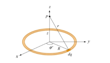
Figure: A non-conducting ring of radius R with uniform charge density λ
Consider a small differential element dl= Rd on the ring. The element carries a charge
Dq =λdl = λ ………….(1)
And its contribution to the electric potential at P is

The electric potential at P due to the entire ring is
 ………….(2)
Where we have substituted Q=2πRλ for the total charge on the ring. In the limit z>>R, the potential approaches its “point-charge” limit:


From Equation 2, the z-component of the electric field may be obtained as

Q9) Discuss Uniqueness Theorems?
A9)
Consider a volume within which the charge density is equal to zero. Suppose that the value of the electrostatic potential is specified at every point on the surface of this volume. The first uniqueness theorem states that in this case the solution of Laplace's equation is uniquely defined.
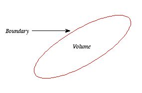
Figure: First Uniqueness Theorem
To proof the first uniqueness theorem we will consider what happens when there are two solutions V1 and V2 of Laplace's equation in the volume shown in Figure. Since V1 and V2 are solutions of Laplace's equation we know that
 =0
=0
 =0
=0
Since both V1 and V2 are solutions, they must have the same value on the boundary. Thus V1 = V2 on the boundary of the volume. Now consider a third function V3, which is the difference between V1 and V2
 =
= -
-
The function V3 is also a solution of Laplace's equation. This can be demonstrated easily:
 =
= -
-  =0
=0
The value of the function V3 is equal to zero on the boundary of the volume since V1 = V2 there. However, property 2 of any solution of Laplace's equation states that it can have no local maxima or minima and that the extreme values of the solution must occur at the boundaries. Since V3 is a solution of Laplace's equation and its value is zero everywhere on the boundary of the volume, the maximum and minimum value of V3 must be equal to zero. Therefore, V3 must be equal to zero everywhere. This immediately implies that
V1 = V2
This proves that there can be no two different functions V1 and V2 that are solutions of Laplace's equation and satisfy the same boundary conditions. Therefore, the solution of Laplace's equation is uniquely determined if its value is a specified function on all boundaries of the region. This also indicates that it does not matter how you come by your solution: if (a) it is a solution of Laplace's equation, and (b) it has the correct value on the boundaries, then it is the right and only solution.
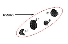
Figure: Boundary
The first uniqueness theorem can only be applied in those regions that are free of charge and surrounded by a boundary with a known potential (not necessarily constant). In the laboratory the boundaries are usually conductors connected to batteries to keep them at a fixed potential.
In many other electrostatic problems we do not know the potential at the boundaries of the system. Instead we might know the total charge on the various conductors that make up the system (note: knowing the total charge on a conductor does not imply a knowledge of the charge distribution ρ since it is influenced by the presence of the other conductors).
In addition to the conductors that make up the system, there might be a charge distribution ρ filling the regions between the conductors. For this type of system the first uniqueness theorem does not apply.
The second uniqueness theorem states that the electric field is uniquely determined if the total charge on each conductor is given and the charge distribution in the regions between the conductors is known.
The proof of the second uniqueness theorem is similar to the proof of the first uniqueness theorem.
Suppose that there are two fields  and
and  that are solutions of Poisson's equation in the region between the conductors. Thus
 .
. =
= 
 .
. =
= 
Where ρ is the charge density at the point where the electric field is evaluated. The surface integrals of  and
and  , evaluated using a surface that is just outside one of the conductors with charge Qi, are equal to
  . Thus
 =
= 
 =
= 
The difference between and
and  , So
, So
 =
=  -
- 
Satisfies the following equations:
 .
. =
=  .
. -
-  .
.
 -
-  =0
=0
 =
=  -
-  =
=  -
-  =0
=0
Consider the surface integral of  , integrated over all surfaces (the surface of all conductors and the outer surface). Since the potential on the surface of any conductor is constant, the electrostatic potential associated with
 and
and  , must also be constant on the surface of each conductor.
Therefore,  =
= -
- will also be constant on the surface of each conductor.
The surface integral of  over the surface of conductor i can be written as
 =
= 
 =0
=0
Since the surface integral of  over the surface of conductor i is equal to zero,
The surface integral of  over all conductor surfaces will also be equal to zero. The surface integral of
  over the outer surface will also be equal to zero since
  on this surface. Thus
 =0
=0
The surface integral  of can be rewritten using Green's identity as
0 =  = -
= -  =
= 
= -  = -
= -  =0
=0
Where the volume integration is over all space between the conductors and the outer surface. Since is always positive, the volume integral of
  can only be equal to zero if
  everywhere. This implies immediately that
 , everywhere, and proves the second uniqueness theorem.
Q10) A molecule of water is placed in an electric field of 2.0  105 N/C. What is the difference between the potential energies for the parallel and the antiparallel orientations of the molecule in this electric field?
A10)
We know, the dipole moment of the water molecule is p = 6.1  1030 Cm. When the dipole is parallel to the electric field, the angle is zero, and

When the dipole is antiparallel to the electric field, the angle is 180 and
 =1.2×
=1.2× J)
J)
Hence the energy difference between the parallel and antiparallel orientations is
2.4  1024 J.
Q11) A flat sheet of paper measuring 22 cm  28 cm is placed in a uniform electric field of 100 N/C. What is the flux through the paper if the paper makes an angle of 900 with the electric field? If the paper makes an angle of 300? (See Figure)
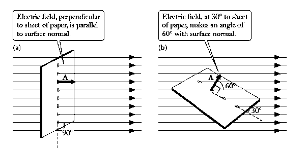
Figure: A flat sheet of paper in a uniform electric field
A11)
For a uniform field and a flat area, the flux is merely the product ΦE = EA cosθ, and since an angle of 90 between the sheet of paper and the electric field means θ= 0.

An angle of 30 between the paper and the electric field means 60

Q12) Consider an imaginary sphere of radius r which has a positive point charge q at its center. What electric flux does the electric field of this point charge produce through the surface of the sphere?
A12)
The positive point charge q produces a radial, outward electric field of magnitude E =q/(4πƐ0r2) that crosses the spherical surface everywhere perpendicularly.
The area of such a sphere is 4πr2, so

Q13) A uranium nucleus (charge +92e) is (approximately) a uniformly charged sphere of radius 7.4 1015 m. What is the electric field inside a uranium nucleus at a point halfway from the center to the surface? What is the radial electric force if such a field acts on a proton at the same point?
A13)
For the field halfway inside a uniformly charged sphere, we can use with r = R/2

The force exerted on a proton by such a field is

In the nucleus of an atom, this large repulsive force is more than compensated by an even larger binding force—the “strong” force—that holds the nucleus together.
Q14) A rod of length l has a charge Q uniformly distributed along its length. Find the electrostatic potential at a distance x from one end of the rod. (See figure)
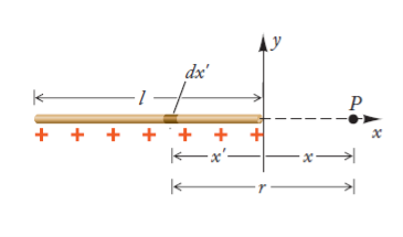
A14)
Consider a small segment dx’ of the rod. Since the charge per unit length is Q/l, the charge in this segment is dQ = (Q/l )dx’. The distance of this segment from the point P is r= x –x’ (here, x’ is a negative quantity. The segment then makes the following contribution to the potential at the point P.

The integral of this over the length of the rod, from x = l to x = 0, gives us the total potential at the position P.


Q15) Discuss method of images in detail for plane conducting surface?
A15)
Method of Images (Plane Conducting Surface)
It is a very powerful technique for solving electrostatics problems involving charges and conductors.
When a charge distribution is placed over an infinite ground plane Coulomb’s law and Gauss’s law cannot be readily applied.
Solving Poisson’s or Laplace’s equation is an option, but this is also mathematically challenging, likely to require a numerical solution
It turns out that an electrically equivalent problem can be created using the image distribution with the ground plane removed.
A simple example of a single point charge Q distanced above a ground plane is shown in Figure.

Figure: Electric field lines
Consider a point charge q held as a distance d above an infinite grounded conducting plane as shown in Figure The electrostatic potential of this system must satisfy the following two boundary conditions:
V(x,y,z) =0

A direct calculation of the electrostatic potential cannot be carried out since the charge distribution on the grounded conductor is unknown.
Note: the charge distribution on the surface of a grounded conductor does not need to be zero.
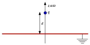
Figure: Method of images
Consider a second system, consisting of two point charges with charges +q and -q, located at z = d and z = -d, respectively as shown in figure. The electrostatic potential generated by these two charges can be calculated directly at any point in space. At a point P = (x, y, 0) on the xy plane the electrostatic potential is equal to

Since this solution satisfies the boundary conditions, it must be the correct solution in the region z > 0 for the system shown in Figure. This technique of using image charges to obtain the electrostatic potential in some region of space is called the method of images.
The electrostatic potential can be used to calculate the charge distribution on the grounded conductor. Since the electric field inside the conductor is equal to zero, the boundary condition for  shows that the electric field right outside the conductor is equal to
 =
=  =
= 
Where σ is the surface charge density and  is the unit vector normal to the surface of the conductor. Expressing the electric field in terms of the electrostatic potential V we can rewrite this equation as

Substituting the solution for V in this equation we find

Only in the last step of this calculation have we substituted z = 0. The induced charge distribution is negative and the charge density is greatest at (x = 0, y = 0, z = 0). The total charge on the conductor can be calculated by surface integrating of σ:
 where
where . Substituting the expression for σ in the integral we obtain
 As a result of the induced surface charge on the conductor, the point charge q will be attracted towards the conductor. Since the electrostatic potential generated by the charge image-charge system is the same as the charge-conductor system in the region where z > 0, the associated electric field (and consequently the force on point charge q) will also be the same. The force exerted on point charge q can be obtained immediately by calculating the force exerted on the point charge by the image charge. This force is equal to
 There is however one important difference between the image-charge system and the real system. This difference is the total electrostatic energy of the system. The electric field in the image-charge system is present everywhere, and the magnitude of the electric field at (x, y, z) will be the same as the magnitude of the electric field at (x, y, -z).
On the other hand, in the real system the electric field will only be non-zero in the region with z > 0. Since the electrostatic energy of a system is proportional to the volume integral of  the electrostatic energy of the real system will be 1/2 of the electrostatic energy of the image-charge system (only 1/2 of the total volume has a non-zero electric field in the real system). The electrostatic energy of the image-charge system is equal to
Wimage = 

The electrostatic energy of the real system is therefore equal to
Wreal =  Wimage =

The electrostatic energy of the real system can also be obtained by calculating the work required to be done to assemble the system. In order to move the charge q to its final position we will have to exert a force opposite to the force exerted on it by the grounded conductor. The work done to move the charge from infinity along the z axis to z = d is equal to

Which is identical to the result obtained using the electrostatic potential energy of the image-charge system.
Q16) Discuss method of images in detail for sphere?
A16)
The method of images can be applied to the case of a charge in front of a grounded spherical conductor. The method is not as straightforward as the case of plane conductors but works equally well.
Consider a charge q kept at a distance a from the centre of the grounded sphere. We wish to obtain an expression for the potential at a point P which is at the position (r, θ), the potential obviously will not depend on the azimuthal angle θ and hence that coordinate has been suppressed.
Let the point P be at a distance from the location of the charge q. The image charge is located at a distance b from the centre along the line joining the centre to the charge q. The line joining the charges and the centre is taken as the reference line with respect to which the angle is measured. Let P be at a distance b from the image charge. Let q’ be the image charge.
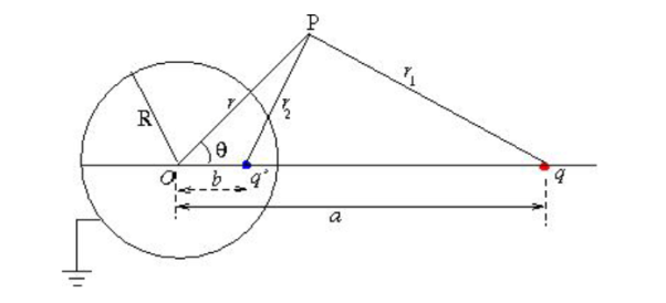
Figure: Method of images for sphere
The potential at P is given by

Using the property of triangle, we can express the potential at P as,

Since the potential vanishes at r=R for all values of θ, the signs of q and q’ must be opposite, and we must have

In order that this relation may be true for all values of cosθ, the coefficient of from both sides of this equation must cancel,

Since q and q’ have opposite sign, this gives,

Substituting this in the θ independent terms above, we get,

Which gives a =R2

It follows that if the object charge is outside the sphere, the image charge is inside the sphere. Using these, the potential at P is given by


The electric field can be obtained by computing gradient of the potential. It can be easily verified that the tangential component of the electric field Eθ =Et =0. The normal component is given by,


The charge density on the surface of the sphere is  (r = R) and is given by


The charge density is opposite to the sign of q since R2-a2 < 0. It is interesting to note that unlike in the case of a conducting plane, the magnitude of the image charge is not equal to that of the object charge but has a reduced value,


Thus the potential can be written as

The following figure shows the variation of charge density on the surface as a function of the angle θ. As expected, when the charge comes closer to the sphere, the charge density peaks around θ=0. Since the distance between the charge and its image is a-b the force exerted on the charge by the sphere is

For a>>R the force is proportional to the inverse cube of the distance of the charge from the centre.
For a  R, let α be the distance of q from the surface of the sphere, a =R+α, α<<R.

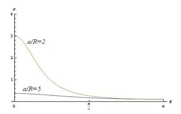
Figure: Graph between α and θ
Consider the limit of R  (one has to be careful here as the origin would now have shifted to extreme left; instead, measure distance from the surface of the sphere. The charge q is located at a distance d=R-a from the surface,

The distance of the image charge,

So that the distance of the image from the surface

Thus we recover the case of a charge in front of an infinite plane.
Q17) Derive the expression for electrostatic energy of a charged sphere
A17)
Suppose we have two charges q1 and q2 separated by the distance r12. There is some energy in the system, because a certain amount of work was required to bring the charges together. We have already calculated the work done in bringing two charges together from a large distance. It is
 …… (1)
We also know, from the principle of superposition, that if we have many charges present, the total force on any charge is the sum of the forces from the others. It follows, therefore, that the total energy of a system of a number of charges is the sum of terms due to the mutual interaction of each pair of charges. If qi and qj are any two of the charges and rij is the distance between them, the energy of that particular pair is

The total electrostatic energy U is the sum of the energies of all possible pairs of charges:
 …… (2)
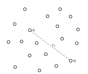
Figure: The electrostatic energy of a system of particles is the sum of the electrostatic energy of each pair.
If we have a distribution of charge specified by a charge density ρ, Thus The electrostatic energy of a system of particles is the sum of the electrostatic energy of each pair.
We shall concern ourselves with two aspects of this energy. One is the application of the concept of energy to electrostatic problems; the other is the evaluation of the energy in different ways.
As an example, let us calculate the energy required to assemble a sphere of charge with a uniform charge density. The energy is just the work done in gathering the charges together from infinity.
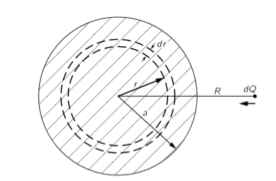
Figure: The energy of a uniform sphere of charge can be computed by imagining that it is assembled from successive spherical shells.
The energy of a uniform sphere of charge can be computed by imagining that it is assembled from successive spherical shells.
Imagine that we assemble the sphere by building up a succession of thin spherical layers of infinitesimal thickness. At each stage of the process, we gather a small amount of charge and put it in a thin layer from r to r+dr. We continue the process until we arrive at the final radius a. If Qr is the charge of the sphere when it has been built up to the radius r, the work done in bringing a charge dQ to it is
 …… (3)
If the density of charge in the sphere is ρ, the charge Qr is
 …… (4)
And the charge dQ is
 … (5)
… (5)
Equation (3) becomes
 …… (6)
The total energy required to assemble the sphere is the integral of dU from r=0 to r=a, or
 …… (7)
Or if we wish to express the result in terms of the total charge Q of the sphere,
 …… (8)
Q18) Discuss the behaviour of conductor in an electric field?
A18)
In conductors the charges can move. For instance, in metals—such as copper, silver, or aluminium—some of the electrons are free, that is, they can move about without restraint within the volume of the metal. If such a conductor is immersed in an electric field, the free electrons move in response to the electric force.
As an excess of electrons accumulates on one part of the conductor, a deficit of electrons will appear on another part of the conductor; thus, negative and positive charges are induced on the conductor. Within the volume of the conductor, the electric field of the induced charges tends to cancel the external electric field in which the conductor was originally immersed.
The accumulation of negative and positive charges on the surfaces of the conductor continues until the electric field generated by these charges exactly cancels the original electric field that initiated the motion of the electrons. Consequently, when the charge distribution on a conductor reaches electrostatic equilibrium, the net electric field within the material of the conductor is exactly zero.
Furthermore, for a conductor in electrostatic equilibrium, any (extra) electric charge deposited on the conductor resides on the surfaces of the conductor. We can prove this using Gauss’ Law: Consider a small Gaussian surface inside the conducting material. Since at equilibrium E = 0 everywhere in this material, the left side of Gauss’ Law vanishes and therefore the right side must also vanish—which means the charge enclosed by any arbitrary surface inside the conducting material is zero.
Obviously, if the charges are not inside the conductor, they must be on the surfaces. Finally, we can say something about the electric field just outside a conductor: the electric field at the surface of a conductor in electrostatic equilibrium is perpendicular to the surface.
The proof is by contradiction: if the electric field had a component tangential to the surface, the free electrons would move along the surface, and the charge distribution would not be in equilibrium.
Note that this argument does not exclude an electric field perpendicular to the surface of the conductor; such an electric field merely pushes the free electrons against the surface, where they are held in equilibrium by the combination of the force exerted by the electric field and the restraining force of the surface of the conductor.
Since the metal is a conductor, the interior field must be zero, and so the gradient of the potential φ is zero. That means that φ does not vary from point to point. Every conductor is an equipotential region, and its surface is an equipotential surface. Since in a conducting material the electric field is everywhere zero, the divergence of E is zero, and by Gauss’ law the charge density in the interior of the conductor must be zero.
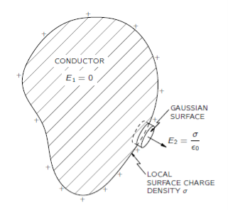
Figure: The electric field just outside the surface of a conductor is proportional to the local surface density of charge.
The electric field just outside the surface of a conductor must be normal to the surface. There can be no tangential component. If there were a tangential component, the electrons would move along the surface; there are no forces preventing that. We know that the electric field lines must always go at right angles to an equipotential surface.
For a gaussian surface, we take a small cylindrical box half inside and half outside the surface, like the one shown in Figure. There is a contribution to the total flux of E only from the side of the box outside the conductor. The field just outside the surface of a conductor is then Outside a conductor:
E = 
Where  is the local surface charge density.
If for the charge on one plate we write
Q =  A
A
Thus Force
F = 
Or, since the electric field between the plates is
E = 
Then
F = 
One would immediately guess that the force acting on one plate is the charge Q on the plate times the field acting on the charge. But we have a surprising factor of one-half. The reason is that E0 is not the field at the charges.
If we imagine that the charge at the surface of the plate occupies a thin layer, the field will vary from zero at the inner boundary of the layer to E in the space outside of the plate. The average field acting on the surface charges is E/2. That is why the factor one-half is in Equation.
Q19) Write Laplace’s and Poisson’s equations for electrostatic potential?
A19)
A useful approach to the calculation of electric potentials is to relate that potential to the charge density which gives rise to it. The electric field is related to the charge density by the divergence relationship
 =
= 
E = Electric field
 = Charge density
 = Permittivity
And the electric field is related to the electric potential by a gradient relationship
E = 
Therefore the potential is related to the charge density by Poisson's equation
 =
=  2V =
2V = 
In a charge-free region of space, this becomes Laplace's equation
 2V = 0
This mathematical operation, the divergence of the gradient of a function, is called the Laplacian. Expressing the Laplacian in different coordinate systems to take advantage of the symmetry of a charge distribution helps in the solution for the electric potential V.
For example, if the charge distribution has spherical symmetry, you use the Laplacian in spherical polar coordinates.
Since the potential is a scalar function, this approach has advantages over trying to calculate the electric field directly. Once the potential has been calculated, the electric field can be computed by taking the gradient of the potential.
Q20) Discuss Laplace’s equations in one dimension?
A20)
Laplace's equation in one dimension
In one dimension the electrostatic potential V depends on only one variable x. The electrostatic potential V(x) is a solution of the one-dimensional Laplace equation
 =0
=0
The general solution of this equation is
V(x) = sx + b
Where s and b are arbitrary constants. These constants are fixed when the value of the potential is specified at two different positions.
Example
Consider a one-dimensional world with two point conductors located at x = 0 m and at x = 10 m. The conductor at x = 0 m is grounded (V = 0 V) and the conductor at x = 10 m is kept at a constant potential of 200 V. Determine V.
The boundary conditions for V are
V(0) = b = 0V
And
V(10) = 10s +b =200V
The first boundary condition shows that b = 0 V. The second boundary condition shows that s = 20 V/m. The electrostatic potential for this system of conductors is thus
V(x) = 20x
The corresponding electric field can be obtained from the gradient of V
E(x) =  = -20 V/m
The boundary conditions used here, can be used to specify the electrostatic potential between x = 0 m and x = 10 m but not in the region x < 0 m and x > 10 m.
If the solution obtained here was the general solution for all x, then V would approach infinity when x approaches infinity and V would approach minus infinity when x approaches minus infinity. The boundary conditions therefore provide the information necessary to uniquely define a solution to Laplace's equation, but they also define the boundary of the region where this solution is valid (in this example 0 m < x < 10 m).
The following properties are true for any solution of the one-dimensional Laplace equation:
Property 1:
V(x) is the average of V(x + R) and V(x - R) for any R as long as x + R and x - R are located in the region between the boundary points. This property is easy to proof:
This property immediately suggests a powerful analytical method to determine the solution of Laplace's equation. If the boundary values of V are
V(x=a) =Va
And
V(x=b) =Vb
Then property 1 can be used to determine the value of the potential at (a + b)/2:

Next we can determine the value of the potential at x = (3 a + b)/4 and at
x = (a + 3 b)/4:


This process can be repeated and V can be calculated in this manner at any point between x = a and x = b (but not in the region x > b and x < a).
Property 2:
The solution of Laplace's equation cannot have local maxima or minima. Extreme values must occur at the end points (the boundaries). This is a direct consequence of property 1.
Property 2 has an important consequence: a charged particle cannot be held in stable equilibrium by electrostatic forces alone (Earnshaw's Theorem). A particle is in a stable equilibrium if it is located at a position where the potential has a minimum value.
A small displacement away from the equilibrium position will increase the electrostatic potential of the particle, and a restoring force will try to move the particle back to its equilibrium position.
There can be no local maxima or minima in the electrostatic potential.
The particle cannot be held in stable equilibrium by just electrostatic forces.
Q21) Discuss Laplace’s equations in two dimensions?
A21)
Laplace's equation in two dimensions
In two dimensions the electrostatic potential depends on two variables x and y. Laplace's equation now becomes
 +
+  =0
=0
This equation does not have a simple analytical solution as the one-dimensional Laplace equation does. However, the properties of solutions of the one-dimensional Laplace equation are also valid for solutions of the two-dimensional Laplace equation:
Property 1:
The value of V at a point (x, y) is equal to the average value of V around this point
Where the path integral is along a circle of arbitrary radius, centered at (x, y) and with radius R.
Property 2:
V has no local maxima or minima; all extremes occur at the boundaries.
Q22) Discuss Laplace’s equations in three dimensions?
A22)
Laplace's equation in three dimensions
In three dimensions the electrostatic potential depends on three variables x, y, and z. Laplace's equation now becomes
 +
+  =0
=0
This equation does not have a simple analytical solution as the one-dimensional Laplace equation does. However, the properties of solutions of the one-dimensional Laplace equation are also valid for solutions of the three-dimensional Laplace equation:
Property 1:
The value of V at a point (x, y, z) is equal to the average value of V around this point

Where the surface integral is across the surface of a sphere of arbitrary radius, centered at (x,y,z) and with radius R.
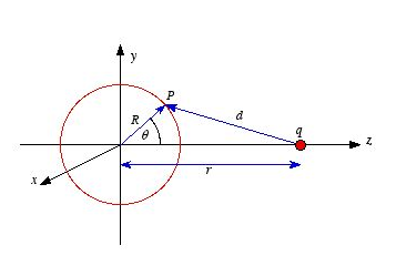
Figure: Laplace's equation in three dimensions
Proof of property 1
To proof this property of V consider the electrostatic potential generated by a point charge q located on the z axis, a distance r away from the center of a sphere of radius R. The potential at P, generated by charge q, is equal to
Vp= 

Where d is the distance between P and q. Using the cosine rule we can express d in terms of r, R and θ
 =
= +
+ -2Rrcosθ
The potential at P due to charge q is therefore equal to
Vp= 

The average potential on the surface of the sphere can be obtained by integrating Vp across the surface of the sphere. The average potential is equal to

Which is equal to the potential due to q at the center of the sphere. Applying the principle of superposition it is easy to show that the average potential generated by a collection of point charges is equal to the net potential they produce at the center of the sphere.
Property 2:
The electrostatic potential V has no local maxima or minima; all extremes occur at the boundaries.
Example
Find the general solution to Laplace's equation in spherical coordinates, for the case where V depends only on r. Then do the same for cylindrical coordinates.
Laplace's equation in spherical coordinates is given by

If V is only a function of r then
 =0
=0
And
 =0
=0
Therefore, Laplace's equation can be rewritten as

The solution V of this second-order differential equation must satisfy the following first-order differential equation:

This differential equation can be rewritten as
 =
=
The general solution of this first-order differential equation is
V(r) =  +b
+b
Where b is a constant. If V = 0 at infinity then b must be equal to zero, and consequently
V(r)=
Laplace's equation in cylindrical coordinates is

If V is only a function of r then
 =0
=0
And
 =0
=0
Therefore, Laplace's equation can be rewritten as

The solution V of this second-order differential equation must satisfy the following first-order differential equation:
r = a = constant
This differential equation can be rewritten as
 =
= 
The general solution of this first-order differential equation is
V(r) = aln(r) +b
Where b is a constant. The constants a and b are determined by the boundary conditions.
Q23) What is the potential due to an electric dipole?
A23)
We already know that electric dipole is an arrangement which consists of two equal and opposite charges +q and -q separated by a small distance 2a.
Electric dipole moment is represented by a vector p of magnitude 2qa and this vector points in direction from -q to +q.
To find electric potential due to a dipole consider charge -q is placed at point P and charge +q is placed at point Q as shown below in the figure.
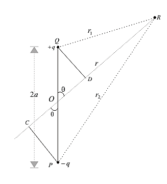
Figure: Potential due to an electric dipole
Since electric potential obeys superposition principle so potential due to electric dipole as a whole would be sum of potential due to both the charges +q and -q. Thus
 ………….(1)
where r1 and r2 respectively are distance of charge +q and -q from point R.
Now draw line PC perpendicular to RO and line QD perpendicular to RO as shown in figure. From triangle POC
Cosθ=OC/OP = OC/a
Therefore OC=acosθ similarly OD=acosθ
Now,
r1 = QR≅RD = OR-OD = r-acosθ
r2 = PR≅RC = OR+OC = r+acosθ


 p| = 2qa
 …………(2)
If we consider the case where r>>a then
 …………(3)
Again since pcosθ= p· where,
  is the unit vector along the vector OR then electric potential of dipole is
 …………(4)
for r>>a
From above equation we can see that potential due to electric dipole is inversely proportional to r2 not 1/r which is the case for potential due to single charge.
Potential due to electric dipole does not only depend on r but also depends on angle between position vector r and dipole moment p.
Q24) Write a note on conservative nature of electrostatic field?
A24)
A force is said to be conservative if the work done by the force in moving a particle from one point to another point depends only on the initial and final points and not on the path followed.
The field where the conservative force is felt is called conservative field. The electric field is a conservative field.
Consider an electric field due to a charge Q. The work done to carry a test charge q from one point A to another point B in the field due to Q does not depend upon the path followed. It depends only upon the initial and final positions A and B. It will be independent of the path followed. So we say that the electric field is conservative in nature.
Conservative nature of electric field means that the line integral of the electric field along a closed path is zero.
Consider two point A and B in an electric field due to a charge Q. Work is done by the electric field in moving a test charge from point A to B along a closed path. For that, we have to add up the work done for all the infinitesimal segments into which the path A and B is divided. Such an integral evaluated along a line is called a line integral.
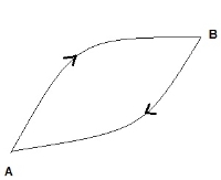
Figure: Conservative nature of Electrostatic Field
Let us consider the integral of electric field along A to B 
The line integral along path B to A:

The line integral along the closed path will be:

But 


Line integral of an electric field along a closed path is zero means that the work done by the electric field is independent of the path and depends only on the endpoints A and B of integration.
Q25) What is Electrostatic Potential?
A25)
If the charge distribution is continuous, the potential at a point P can be found by summing over the contributions from individual differential elements of charge. Dq
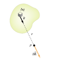
Figure: Continuous charge distribution
Consider the charge distribution shown in Figure. Taking infinity as our reference point with zero potential, the electric potential at P due to dq is

Summing over contributions from all differential elements, we have

We established the relation between  and V. If we consider two points which are separated by a small distance
  , the following differential form is obtained.
DV = -
In Cartesian coordinates,
E = Ex  + Ey
+ Ey + Ez
+ Ez
And  = dx
= dx  + dy
+ dy + dz
+ dz
DV = ( Ex  + Ey
+ Ey + Ez
+ Ez ) .( dx
  + dy
+ dy + dz
+ dz )
)
DV = ( Ex dx+ Eydy + Ezdz
This implies
Ex =  Ey =
Ey =  Ez =
Ez = 
By introducing a differential quantity called the “del (gradient) operator”

The electric field can be written as

 =-
=- 
Notice that ∇ operates on a scalar quantity (electric potential) and results in a vector quantity (electric field). Mathematically, we can think of  as the negative of the gradient of the electric potential V. Physically, the negative sign implies that if V increases as a positive charge moves along some direction, say x, with , then there is a non-vanishing component of
  in the opposite direction(-Ex
  )
)
In the case of gravity, if the gravitational potential increases when a mass is lifted a distance h, the gravitational force must be downward.
If the charge distribution possesses spherical symmetry, then the resulting electric field is a function of the radial distance r, i.e.  = Er
= Er 
In this case, .dV=- Er dr.
If V(r) is known, then  may be obtained as

For example, the electric potential due to a point charge q is
V = 

Using the above formula, the electric field is simply
E = 

Q26) Derive Gauss’s law for spherical symmetry?
A26)
Spherical Symmetry
Charge distributions with spherical symmetry include points, spheres, thin or thick spherical shells, etc., and concentric layers of such objects.
Since the point charge is spherically symmetric, so must be the electric field. This
Spherical symmetry requires that the magnitude of the electric field be the same at all points at equal distances from the center, that is, at all points on a spherical surface centered on the charge, since otherwise the electric field would make an unacceptable distinction between such points.
Furthermore, the spherical symmetry requires that the direction of the electric field be rotationally symmetric around any radial line extending outward from the charge. The only direction of the electric field consistent with this requirement is radial, since any non-radial component would make an unacceptable distinction between different directions around this line.
Now consider a spherical Gaussian surface of radius r centered on the charge q, as shown in Figure. According to the symmetry arguments, at all points on this surface, the electric field must be radial and constant.
On this Gaussian surface, the normal component of the electric field is the same as the total field, E⊥ = E; and the flux is therefore

The charge inside is merely the point charge q, so Gauss’ Law tells us

From which we immediately obtain Coulomb’s Law

Q27) Derive Gauss’s law for cylindrical symmetry?
A27)
Cylindrical Symmetry
Consider a pair of line elements P1 and P2 of the wire, as shown. The electric fields produced by the two elements of the pair when summed give a resultant electric field which is radial (the components normal to the radial
Vector cancel). This is true for any such pair and hence the total field at any point P is radial. Finally, since the wire is infinite, electric field does not depend on the position of P along the length of the wire. In short, the electric field is everywhere radial in the plane cutting the wire normally, and its magnitude depends only on the radial distance r.
To calculate the field, imagine a cylindrical Gaussian surface, as shown in the figure.
Since the field is everywhere radial, flux through the two ends of the cylindrical Gaussian surface is zero. At the cylindrical part of the surface, E is normal to the surface at every point, and its magnitude is constant, since it depends only on r. The surface area of the curved part is 2πrl, where l is the length of the cylinder.
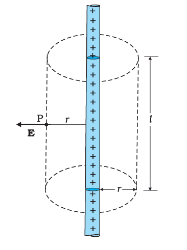
Figure: The Gaussian surface for a long thin wire of uniform linear charge density.
Flux through the Gaussian surface = flux through the curved cylindrical part of the surface
= E × 2πrl
The surface includes charge equal to λl. Gauss’s law then gives
E × 2πrl = λl/ε0
i.e., E =λ/2rπε0
Vectorially, E at any point is given by
E =λ/2rπε0 
Where  is the radial unit vector in the plane normal to the wire passing through the point. E is directed outward if λ is positive and inward if λ is negative.
Q28) Derive Gauss’s law for planar symmetry?
A28)
Planar Symmetry
Let  be the uniform surface charge density of an infinite plane sheet. We take the x-axis normal to the given plane. By symmetry, the electric field will not depend on y and z coordinates and its direction at every point must be parallel to the x-direction.
We can take the Gaussian surface to be a rectangular parallelepiped of cross sectional area A, as shown. As seen from the figure, only the two faces 1 and 2 will contribute to the flux; electric field lines are parallel to the other faces and they, therefore, do not contribute to the total flux.
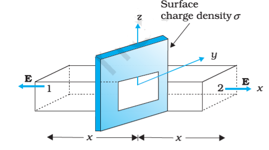
Figure: Gaussian surface for a uniformly charged infinite plane sheet.
The unit vector normal to surface 1 is in –x direction while the unit vector normal to surface 2 is in the +x direction. Therefore, flux E. S through both the surfaces are equal and add up. Therefore the net flux through the Gaussian surface is 2 EA. The charge enclosed by the closed surface is σA. Therefore by Gauss’s law,
2 EA = σA/ε0
Or, E = σ/2ε0
Vectorically,
E = σ/2ε0 
Where  is a unit vector normal to the plane and going away from it. E is directed away from the plate if σ is positive and toward the plate if σ is negative.
Note that the above application of the Gauss’ law has brought out an additional fact: E is independent of x also.
For a finite large planar sheet, equation is approximately true in the middle regions of the planar sheet, away from the ends.
Q29) Derive the expression electrostatic energy density?
A29)
Suppose we wish to build up a charge density ρ( ) in some region of space with relevant electric potential value V(
 ). The work needed to assemble such a charge configuration will be stored eventually in the form of electrostatic potential energy. The procedure is to start with an initial state where we have complete empty space with whatsoever no charges and no electric potentials, i.e., ρ(
 ) = 0 and V(
 ) = 0, everywhere
Bringing incremental amounts of charges from infinity and distributing those appropriately we aim to reach a final state where the charge density and the potential have their final forms, given as ρ( ) and V(
 ).
).
During the procedure we imagine that we have obtained an intermediate configuration (described under primed notation) where the charge density and the potential lie some-where between their initial and final values, i.e.,
0< ρ’ ( ) < ρ (
 ) and 0< V′ (
 ) < V (
 )
)
Carrying further incremental charges ∆q and placing into infinitesimal sized volume element ∆v we perform and additional work
∆W=V′( ) ∆q, where ∆q= ∆ρ′∆v
We require that all parts of the charge distribution are brought to their final charge values at the same pace and uniformity. On this purpose we introduce a gauge parameter g that can be tuned from zero to unity and serves to keep trace of the transition from the initial to the final charge configuration. Increasing g will make ρ′ and V′ to increase and grow to their final values ρ and V. The linkage between the intermediate and final values is therefore
ρ′=gρ, V′=gV, ∆ρ′= ∆g ρ
Under an additional amount of charge ∆q put at  where the potential is V′(
 ) the increase in the energy is
∆W=V′( ) ∆q
) ∆q
=V′( ) ∆ρ′∆v
=gV( ) ∆g ρ(
 )∆v
)∆v
To find the total work
W=∫∆W
We must sum over infinitely many small contributions attained through the variation of parameter g from 0 to its full value 1, as well as contributions coming from infinitesimal volume elements to yield the overall energy in the overall space.
We thus have
 ………..(1)
In the expression given by eq.(1), using Gauss’ law

We obtain

This expression can be cast into a more convenient form if one uses the identity

 V
V
Hence we equivalently write

Using the divergence theorem we confirm the first volume integral into a surface integral, and in the second volume integral replace  V by -
 and hence obtain

Clearly, surface S which is supposed to bound the entire space should have boundaries extending far out to infinity where the electric potential has zero value. Thus omitting the first integral we reach the following alternative expression for the total energy, expressed solely in terms the electric field in the overall space:
 …………(2)
Or simply W= ∫dv u( ) in which
 is the electrostatic energy density.