Unit 1
- Explain Kirchoff’s law?
The algebraic sum of currents meeting at a junction or node in a electric circuit is zero or the summation of all incoming current is always equal to summation of all outgoing current in an electrical network.
Explanation
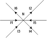
Assuming the incoming current to be positive and outgoing current negative we have


I e incoming current = ∑ outgoing current thus, the above Law can also be stated as the sum of current flowing towards any junction in an electric circuit is equal to the sum of currents flowing away from that junction
Kirchhoff’s Voltage Law (KVL)
Statement : the algebraic summation of all Voltage in any closed circuit or mesh of loop zero.
Ie ∑ Voltage in closed loop = 0 the summation of the Voltage rise (voltage sources) is equal to summation of the voltage drops around a closed loop in 0 circuit for explanation from here
Determination of sigh and direction of currents (Don’t write in exams just for understanding)

Current entering a resistor is +ve and leaving should be –ve
Now
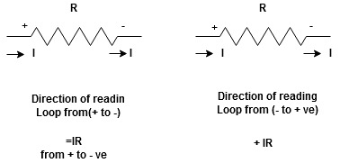


Potential RisePotential Drop
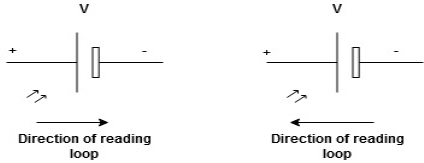
We are reading from +V to –Vwe are reading from –V to +V
 potential drops
 potential rise
 -V
-V +V
+V
Given Circuit
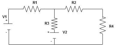
First identify no of loops and assign direction of current flowing in loop
Note : no of loops in circuit = No, of unknown currents = no, of equations in the circuit
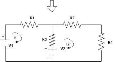
Note : keep loop direction and current direction same ie either clockwise or anticlockwise for all loops I1 I2
Now according to direction of direction assign signs (+ve to –ve) to the resistors
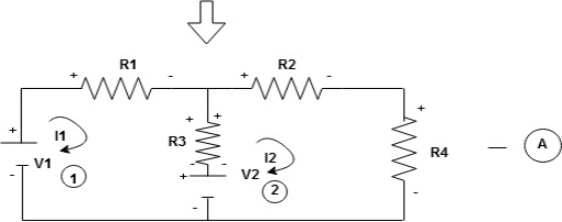
Note : voltage sources (V) polarities does not change is constant.
Note: for common resistor between 2 loops appearing in the circuit like R3 give signs according to separate loops as shown
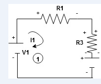
When considering only loop no 1 (+ R3 - )
- B
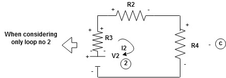
Now consider diagram A and write equations
Two loops  two unknown currents
  two equation
Apply KVL for loop ① [B. Diagram ]
(+ to drop -) = - sign and (- to rise +) = + sign
 for drop = -sign
 for rise = + sign
-
-( ) R2 is considered because in R3,2 currents are flowing
  and
and  and we have taken (
 ) because we are considering loop no 1 and current flowing is
  in loop no 1
 )
)
Similarly for loop no. 2 currents flowing is  resistor R3 it should be
  )R3
)R3
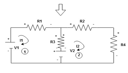
Consider loop no. 1 apply KVL
- …….①
…….①
-
Consider loop no. 2 apply KVL
- …….②
…….②
-
After solving equation ① and ② we will get branch current  and
and 
2. Solve the circuit by nodal analysis and find Va.
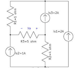
Solution
a) Choose a reference node, label node voltages:
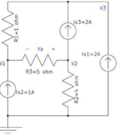
b) Apply KCL to each node:
Node 1:
−Is2+V1−V2R3+V1−V3R1=0→6V1−V2−5V3=5−------------------------------(1)
Node 2:
Is3+(V2−V1)/R3+V2/R2=0→−4V1+9V2----------------------------------------(2)
Node 3:
−Is1−Is3+(V3−V1)/R1=0→V3−V1=4----------------------------------------------(3)
(1), (2) and (3) imply that V1=37v,V2=12v,V3=41v.
c) Find the required quantities: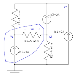
If we apply KVL in the loop shown above:
−V1−Va+V2=0→Va=−25v.
3. Solve the circuit by mesh analysis and find the current Ix and the voltage across R2.
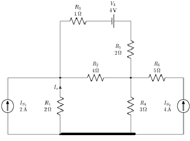
There are four meshes in the circuit. So, we need to assign four mesh currents. It is better to have all the mesh currents loop in the same direction (usually clockwise) to prevent errors when writing out the equations.
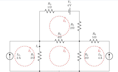
A mesh current is the current passing through elements which are not shared by other loops. This is to say that, for example, the current of R3 is I4 , the current of R6 is I3 and so on. But how about elements shared between two meshes such as R2? Current of such elements is the algebraic sum of both meshes. Lets assume that the current of R2 is defined with direction from right to left, algebraic sum means that its current would be I4−I2. If one assume the inverse direction, i.e. from bottom to top, it would be I2−I4 because I2 is passing through R2 with the same direction of its defined current but I4 is passing with the reverse direction.
Lets define current directions for all elements and find them in terms of mesh currents:
Resistors
IR1
R1 is shared between mesh #1 and mesh #2, i.e. meshes with currents I1 and I2. Therefore, IR1 equals to the algebraic sum of I1 and I2. To determine signs of mesh currents for IR1, we need to compare mesh current directions with the IR1 direction.
It is clear that I1 is in the same direction of IR1 and I2 is in the opposite direction. Thus, IR1=I1−I2.
IR2
We know that IR2=I2−I4.
IR3
R3 is not shared between meshes. It is only in mesh #4 and because IR3 is in the same direction of I4, IR3=I4.
IR4
Similar to IR1: IR4=I2−I3.
IR5
Similar to IR3: IR5=I4.
IR6
It is similar to IR3 with one exception; the direction of IR6 is opposite to the direction of the mesh current, i.e. I3. Therefore, IR6=−I3.
Voltage Source
Similar to IR6, since the defined current direction is opposite to the mesh current direction: IV1=−I4.
Current Sources
Current sources are known but finding their values in term of mesh currents helps to find mesh current values.
IS1
It is not shared between any mesh and in the same direction as the mesh current. Thus IS1=I1=2A
IS2
It is not shared between any mesh and in the reverse direction of the mesh current. Thus IS2=−I3=4A
Known and unknown mesh currents
Current sources, specially when they are not shared between meshes, are very useful in determining mesh current values.
So far we have found:
I1=2A
I3=−4A
But I2 and I4 are still unknown.
For mesh of I2 (Mesh II).
A mesh equation is in fact a KVL equation using mesh currents. We start from a point and calculate algebraic sum of voltage drops around the loop.
For example, instead of IR2, we use I2−I4.
With some practice, write KVL equations using mesh currents directly.
For resistors, the voltage drop equals to the resistance multiplied by mesh currents considering mesh currents in KVL writing direction with positive sign and for the ones in the opposite direction with negative sign.
Lets assume for mesh 2 we start from left-bottom toward top:
(I2−I1)×R1
I2 is in the same direction of our KVL and therefore comes with positive sign but I1 is in the opposite direction and comes with negative sign.
Similarly:
(I2−I1)×R1+(I2−I4)×R2+(I2−I3)×R4=0
(I2−2)×2+(I2−I4)×4+(I2+4)×3=0
2I2−4+4I2−4I4+3I2+12=0
9I2−4I4=−8------------------------- (1)
For Mesh IV, starting from left-bottom toward top and then right:
I4×R3+
This is because R3 is not a shared element.
I4×R3−4V+I4×R5+(I4−I2)×R2=0
I4×1−4+I4×2+(I4−I2)×4=0
7I4−4I2=4------------------------------------------- (2)
Solving equations 1 and 2, we obtain:
I2=−4047A,I4=447AI2=−4047A,I4=447A
Finding Ix
The current of any branch is equal to the algebraic sum of associated mesh currents. I1 is in the opposite direction of Ix and I2 is in the same direction as Ix. Therefore:
Ix=I2−I1=−2.851A
Finding voltage across R2
IR2=I2−I4=0.9362A
VR2=IR2×R2=0.9362×4=3.7447V.
4. Write a note on delta to star conversions?
Star to delta conversion to final equivalent resistance
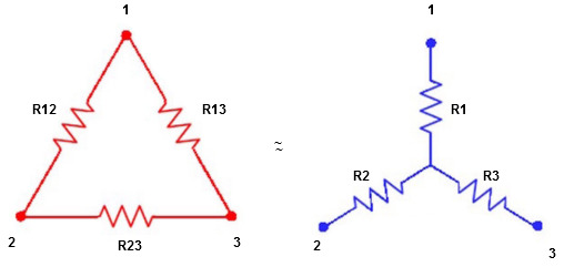
We know that (from delta to star conversion)
R1 =  …….①
…….①
R2 =  …..②
…..②
R1 =  ……③
……③
Multiply ① X ② L.H.S and R.H.S
R1 R2 =  …….④ where
Similarly multiply ② X ③
R2 R3 =  …….⑤
…….⑤
And ③ X①
R1 R3 =  …….⑥
…….⑥
Now add equation ④, ⑤, and ⑥ L.H.S and R.H.S


 ……refer eq. ②
 =
=  +
+  +
+ 
 =
=  +
+ 

(Delta) star star
Similarly R23 = R2+R3 + 
R23 = R1+R2 + 
5.Using superposition theorem Find the current through  resistance.
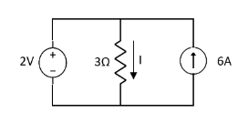
Solution:
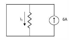
 1= 0
1= 0
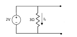
 2=
2=
 1 +
1 +  2
2 
Special Case:
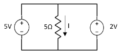
Since two voltage sources with different magnitude in parallel which cannot be connected as in single branch two different current is not possible (if 5V than I = zero).
6. Find RN, IN, the current flowing through and load Voltage across the load resistor in fig (1) by using Norton’s Theorem.

Step 1:
Short the 1.5 Ω load resistor.
Step 2:
Norton current.
Short AB terminals to obtain IN . The total resistance of the circuit is
2Ω + (6Ω || 3Ω)
RT = 4 Ω
IT = V / RT = 12/ 4 = 3 A
IN = 3 A x [ 6Ω / 3 + 6 )] = 2A
IN = 2A
Step 3:
Open current sources, Short Voltage sources and Open Load resistor.
Step 4:
Calculate Norton Resistance (RN)
Reduce 12V dc source. 3Ω resistor is in series with combination of 6Ω and 2Ω resistor
3Ω + (6Ω||2Ω)
3Ω + 1.5 Ω = 4.5 Ω; RN = 4.5 Ω
Step 5:
Connect RN in parallel with current source IN and the load resistor.
Step 6:
The load current through Load resistor
IL = IN x [ RN /(RN + RL)
=2 A x ( 4.5 / 4.5 + 1.5 K) = 1.5 A
IL = 1.5 A
The voltage across load resistor
VL = IL x RL
= 1.5 x 1.5
VL = 2.25 V
7.Explain the transient response of R-L circuit?
Transients in R-L
Consider the following series RL circuit diagram.
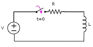
In the above circuit, the switch was kept open up to t = 0 and it was closed at t = 0. So, the DC voltage source having V volts is not connected to the series RL circuit up to this instant. Therefore, there is no initial current flows through inductor.
The circuit diagram, when the switch is in closed position is shown in the following figure.
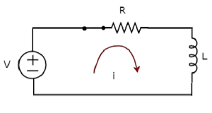
Now, apply KVL around the loop.
V=Ri+ L di/dt
di/dt+⟮R/L⟯i=VL Equation 1
The above equation is a first order differential equation and it is in the form of
dy/dt+Py=Q Equation 2
By comparing Equation 1 and Equation 2, we will get the following relations.
x=t
y=i
P=R/L
Q = V/L
The solution of Equation 2 will be
Ye∫pdx=∫Qe∫pdxdx+k-------------------------Equation 3
Where, k is the constant.
Substitute, the values of x, y, P & Q in Equation 3.
Ie∫⟮R/L⟯dt=∫(V/L)⟮e∫⟮R/L⟯dt⟯dt+k
⇒ie⟮R/L⟯t=V/L∫e⟮R/L⟯tdt+k
⇒ie⟮R/L⟯t=V/L{e⟮R/L⟯t/R/L}+k
⇒i=V/R+ke−⟮R/L⟯t--------------------------Equation 4
We know that there is no initial current in the circuit.
Hence, substitute, t = 0 and 𝑖 = 0 in Equation 4 in order to find the value of the constant k.
0=V/R+ke−⟮R/L⟯(0)0=
0=VR+k(1)
k=−V/R
Substitute, the value of k in Equation 4.
i=V/R+⟮−V/R⟯e−⟮R/L⟯t
i=V/R−V/Re−⟮R/L⟯t
Therefore, the current flowing through the circuit is
i=−V/R e−⟮R/L⟯t+V/R Equation 5
So, the response of the series RL circuit, when it is excited by a DC voltage source, has the following two terms.
- The first term −V/ R e−⟮R/L⟯t corresponds with the transient response.
- The second term V/R corresponds with the steady state response.
- These two responses are shown in the following figure.
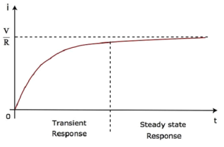
We can re-write the Equation 5 as follows −
i=V/R⟮1−e−⟮R/L⟯t⟯
⇒i=VR⟮1−e−⟮tτ ) Equation 6
Where, τ is the time constant and its value is equal to LR.
Both Equation 5 and Equation 6 are same. But, we can easily understand the above waveform of current flowing through the circuit from Equation 6 by substituting a few values of t like 0, τ, 2τ, 5τ, etc.
If a sinusoidal signal is applied as an input to a Linear electric circuit, then it produces a steady state output, which is also a sinusoidal signal. Both the input and output sinusoidal signals will be having the same frequency, but different amplitudes and phase angles.
We can calculate the steady state response of an electric circuit, when it is excited by a sinusoidal voltage source using Laplace Transform approach.
The s-domain circuit diagram, when the switch is in closed position, is shown in the following figure.
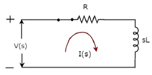
In the above circuit, all the quantities and parameters are represented in s-domain. These are the Laplace transforms of time-domain quantities and parameters.
The Transfer function of the above circuit is
H(s)=I(s)V(s)
⇒H(s)=1Z(s
⇒H(s)=1R+sL
Substitute s=jω in the above equation.
H(jω)=1R+jωL
Magnitude of H(jω) is
|H(jω)|=1R2+ω2−−−−−−−√L2|H(jω)|=1R2+ω2L2
Phase angle of H(jω) is
∠H(jω)=−tan−1⟮ωL/R)
We will get the steady state current iss(t) by doing the following two steps −
- Multiply the peak voltage of input sinusoidal voltage and the magnitude of H(jω)
- Add the phase angles of input sinusoidal voltage and H(jω).
The steady state current iss(t) will be
Iss(t)=Vm/ R2+ω2L2 (sin⟮ωt+φ−tan−1⟮ωL/R⟯⟯
Substitute the value of iss(t) in Equation 2.
i(t)=Ke−⟮t/τ⟯+Vm/  R2+ω2L2 sin⟮ωt+φ−tan−1⟮ωL/R⟯⟯ --------------Equation 3
We know that there is no initial current in the circuit.
Hence, substitute t = 0 & i(t) = 0 in Equation 3 in order to find the value of constant, K.
0=Ke−⟮0τ⟯+Vm /  R2+ω2L2 [sin⟮ω(0)+φ−tan−1⟮ωL/R⟯
⇒0=K+Vm/  R2+ω2L2 sin⟮φ−tan−1⟮ωL/R)
⇒K=−Vm/  R2+ω2L2 sin⟮φ−tan−1⟮ωL/R)
Substitute the value of K in Equation 3.
i(t)=−Vm/ R2+ω2L2sin⟮φ−tan−1⟮ωL/R⟯⟯e−⟮t/τ⟯+Vm/
 R2+ω2L2sin⟮ωt+φ−tan−1⟮ωL/R⟯⟯
-----------------Equation 4
Equation 4 represents the current flowing through the series RL circuit, when it is excited by a sinusoidal voltage source. It is having two terms. The first and second terms represent the transient response and steady state response of the current respectively.
We can neglect the first term of Equation 4 because its value will be very much less than one. So, the resultant current flowing through the circuit will be
i(t)=Vm/  R2+ω2L2 sin⟮ωt+φ−tan−1⟮ωL/R⟯
It contains only the steady state term. Hence, we can find only the steady state response of AC circuits and neglect transient response of it.
Transient response:
The transient response time T is measured in terms of τ = R x C, in seconds, where R is the value of the resistor in ohms and C is the value of the capacitor in Farads. This then forms the basis of an RC charging circuit were 5T can also be thought of as “5 x RC”.
8. Explain the transient response of series R-L-C circuit?
The circuit shown is called series R-L-C circuit. When the switch is closed the equation describes the response of the system by applying KVL around the mesh.
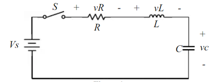
vR + vL + vc = Vs -----------------------------(1)
The current flowing in the circuit is
i = C dvc/dt -----------------------------(2)
Thus, the voltages vR and vL are given by
vR = iR = RC dvc/dt ----------------------------------(3)
vL = L di/dt = LC d2vc/dt2 -----------------------------------------(4)
Substituting eq (3) and (4) in (1) we get
d 2 vc/dt 2 + R/L dvc/dt + 1/LC vc = 1/LC Vs ---------------------------(5)
The solution to equation(5) is the linear combination of the homogeneous and the particular solution vc = vcp + vch
The particular solution is
vcp=vs --------------------------------------------(6)
And the homogeneous solution satisfies the equation
d 2 vch/dt2 + R/L d vch/dt + 1/LC vch =0 ----------------------------(7)
Assuming the homogeneous solution is of the form Ae st and by substituting into equation(7) we get
s 2 + R/L s + 1/LC =0 ------------------------------(8)
By defining α = R/2L ; Damping rate ----------------------------(9)
w0 = 1/  : Natural frequency.-------------------------(10)
The characteristic equation becomes
s 2 + 2 α s + wo 2 = 0 -------------------------------------(11)
The roots of the characteristic equation are :
s 1 = -α +  2 – wo 2 --------------------------------------------(12)
s2 = -α -  2 – wo 2 --------------------------------------------------------------------(13)
And the homogeneous solution becomes
Vch = A1 e s1t + A2 e s2t ----------------------------------------------------------(14)
The total solution is
Vc = Vs + A1 e s1t + A2 es2t ------------------------------------------------------------------(15)
The parameters A1 and A2 are constants and can be determined by the application of the initial conditions of the system vc(t=0) and dvc(t)/dt
The value of the  2 – wo 2 determine the behaviour of the response.
α = wo then s1 and s2 are equal and real numbers ; no oscillatory behaviour
Critically Damped System.
α>wo and s1 and sr are real numbers but not equal and no oscillatory behaviour then it is over damped system.
Vc = Vs + A1 es1t + A2 e s2t
α<wo  2 – wo 2 = j
  2 – α 2 . In this case the roots s1 and s2 are complex numbers.
s 1 = - α + j  2 – α 2
s2 = - α - j  2 – α 2
The system exhibits underdamped system.
9. Explain single phase emf generation?
EMF equation for 1ø transformer:-
Consider ac sinusoidal flux,
Ø=Øm sinwt
By faraday’s law of electromagnetic induction EMF induced is, for a single turn.
e=−d∅dt
For N, number of turn
e=−N . d∅dt
e = N ((−d∅dt ∅m sinwt)
=N∅mcoswtw
=−N∅m2πfcoswt
e=∅mN.2πsin(wt−π2)
Emax=N.∅m2πf
ERMS =emax2–√=4.44NN∅mf
Primary induced emf,E1=4.44N1∅mf
E2=4.44N2∅mf
10. Explain j operator ?
- In electrical engineering this type of number is called an “imaginary number” and to distinguish an imaginary number from a real number the letter “ j ” known commonly in electrical engineering as the j-operator, is used.
- Thus, the letter “j” is placed in front of a real number to signify its imaginary number operation.
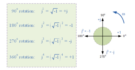
- The j-operator has a value exactly equal to √-1, so successive multiplication of “ j “, ( j x j ) will result in j having the following values of, -1, -j and +1.
- As the j-operator is commonly used to indicate the anticlockwise rotation of a vector, each successive multiplication or power of “ j “, j2, j3 etc, will force the vector to rotate through a fixed angle of 90o in an anticlockwise direction as shown below. Likewise, if the multiplication of the vector results in a -j operator then the phase shift will be -90o, i.e. a clockwise rotation.
Vector rotation of j operator:
11. Explain series and parallel circuits?
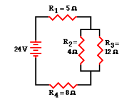
To simplify the circuit by replacing the two parallel resistors with a single resistor with an equivalent resistance. The equivalent resistance of a 4-Ω and 12-Ω resistor placed in parallel can be determined using the usual formula for equivalent resistance of parallel branches:
1 / Req = 1 / R1 + 1 / R2 + 1 / R3 ...
1 / Req = 1 / (4 Ω) + 1 / (12 Ω)
1 / Req = 0.333 Ω-1
Req = 1 / (0.333 Ω-1)
Req = 3.00 Ω
Based on this calculation, it can be said that the two branch resistors (R2 and R3) can be replaced by a single resistor with a resistance of 3 Ω. This 3 Ω resistor is in series with R1 and R4. Thus, the total resistance is
Rtot = R1 + 3 Ω + R4 = 5 Ω + 3 Ω + 8 Ω
Rtot = 16 Ω
Itot = ΔVtot / Rtot = (24 V) / (16 Ω)
Itot = 1.5 Amp
The 1.5 Amp current calculation represents the current at the battery location. Yet, resistors R1 and R4 are in series and the current in series-connected resistors is everywhere the same. Thus,
Itot = I1 = I4 = 1.5 Amp
12. Explain resonance in series RLC circuit?
At resonant frequency, XL = Xc
XL = 2 π f L and Xc = 1/ 2π f C
2 π f L = 1/ 2π f C
At resonance f = fr and on solving above equation we get,
1/ 2π  = fr Hz
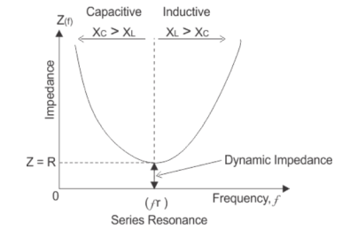
At resonance in series RLC circuit, two reactances become equal and cancel each other. So, in resonant series RLC circuit, the opposition to the flow of current is due to resistance only. At resonance, the total impedance of series RLC circuit is equal to resistance i.e Z = R, impedance has only real part but no imaginary part and this impedance at resonant frequency is called dynamic impedance and this dynamic impedance is always less than impedance of series RLC circuit.