Unit 2
- Explain generation of three phase emf?
In a three – phase a.c. generator three coils are fastened rigidly together and displaced from each other by 1200. It is made to rotate about a fixed axis in a uniform magnetic field. Each coil is provided with a separate set of slip rings and brushes.
These voltages can be produced by a three-phase AC generator having three identical windings displaced separately from each other by 120 degrees electrical. Three electrical circuits/coils are equally distributed over the margin of a permanent magnetic rotor.
An emf is induced in each of the coils with a phase difference of 120o. Three coils a1 a2, b1 b2, and c1 c2 are mounted on the same axis but displaced from each other by 1200, and the coils rotate in the anticlockwise direction in a magnetic field (Fig: a).
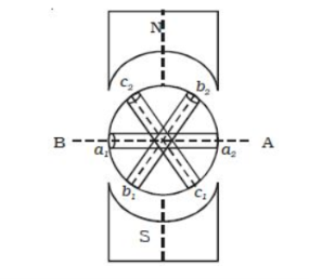
When the coil a1 a2 is in position AB, emf induced in this coil is zero and starts increasing in the positive direction. At the same instant, the coil b1b2 is 120o behind coil a1a2, so that emf induced in this coil is approaching its maximum negative value and the coil c1 c2 is 2400 behind the coil a1 a2, so the emf induced in this coil has passed its positive maximum value and is decreasing.
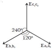
According to Faraday’s law, emf induced in three coils. The emf induced in these three coils will have phase dissimilarity of 1200. i.e. if the induced emf of the coil C1 has a phase of 00, then induced emf in the coil C2 lags that of C1 by 1200 and C3 lags that of C2 1200.
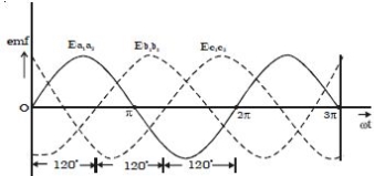
Thus, the EMFs induced in all the three coils are equal in magnitude and of the same frequency. The emf induced in the three coils are;
ea1a2 = E0 sin ωt
eb1b2 = E0 sin (ωt – 2π/3)
ec1c2 = E0 sin (ωt – 4π/3)
The emf induced and phase difference in the three coils a1 a1, b1 b1 and c1 c1 are shown in Fig: b & Fig:c.
2. Explain delta and star connections?
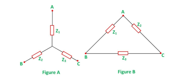
In star to delta conversion, the star-connected load is to be converted into delta connection. Suppose we have a star connected load as shown in the figure above, and it has to be converted into a delta connection as shown in figure B.
The following Delta values are as follows:
Z1 = Za Zb + Zb Zc + Zc Za / Zc =  Zb/Zc
Zb/Zc
Z2 = Za Zb + Zb Zc + Zc Za / Zb =  Zb/Zb
Zb/Zb
Z3 = = Za Zb + Zb Zc + Zc Za / Za =  Zb/Za
Zb/Za
Delta to Star Conversion
A delta connection network is given as shown above, in figure B and it has to be transformed into a star connection, as shown above, in the figure A. The following formulas given below are used for the conversion:
ZA = Z1 Z2/ Z1 + Z2 + Z3
ZB = Z2Z3/ Z1 + Z2 + Z3
ZC = Z1Z3 / Z1 + Z2 + Z3
If the values of Z1, Z2 and Z3 are given, then by putting these values of the Impedances in the above equations, the conversion of delta connection into star connection can be performed.
3. Explain line and phase quantities?
Line voltage is the voltage measured between any two lines in a three-phase circuit.
Phase voltage is the voltage measured across a single component in a three-phase source or load.
Line current is the current through any one line between a three-phase source and load.
Phase current is the current through any one component comprising a three-phase source or load.
In balanced “Y” circuits, the line voltage is equal to phase voltage times the square root of 3, while the line current is equal to phase current.
For Y circuits :
E line =  E phase
I line = I phase
In balanced Δ circuits, the line voltage is equal to phase voltage, while the line current is equal to phase current times the square root of 3.
For ∆ circuits :
E line = E phase
I line =  I phase
4. Explain solution of two phase with balanced load?
A two-phase motor is a system that has two voltages 90 degrees apart, which is no longer in use nowadays. The alternator is composed of two windings placed at 90 degrees from each other.
They require 2 live and one ground wire that work in two phases. One increases the current up to 240v for the motion, and the other one maintains the fluidity of the current for the use of the motor.
The problem with this was that if you used 3 wires - 2 hot wires and a neutral, the neutral currents don’t cancel as they do with 3 phase. This can be solved with a 4 wire system, (or 4 hot wires plus a neutral). Then the neutral currents do cancel.
5. Explain power in three phase balanced circuits?
In 3 phase circuits (balanced load), the power is defined as the sum of various powers in a three-phase system. i.e.
P = 3 Vph Iph cos ɸ
Power in star connections in a 3 phase circuits is given as
P = 3 V L /  I L cos ɸ -----------------------------(1)
The phase voltage and line voltage in the star connection is represented as shown below:
Vph = V L/ and Iph = IL
Therefore equation(1) can be written as
P =  VL IL cos ɸ ------------------------(2)
Power in delta connections in 3 phase circuits is given by the equation shown below
P = 3 VL IL/ cos ɸ ----------------------------(3)
In delta connections the relation between phase and line voltage and phase and line current is given by
Vph = VL and Iph = IL / 
Hence equation(3) can be written as
P= 3 VL IL /  cos ɸ -------------------------------(3)
Thus, the total power in a 3- phase balanced load system irrespective of their connections whether the system is star connected or delta connected the power is given by the relation:
 VL IL cos ɸ
6. Explain B-H curve?
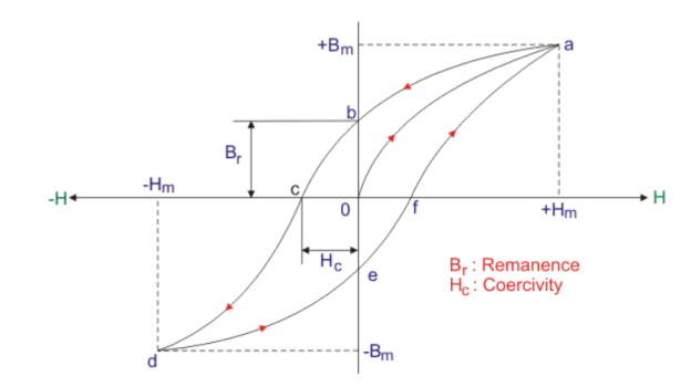
- Step 1:
When supply current I = 0, so no existence of flux density (B) and magnetizing force (H). The corresponding point is ‘O’ in the graph above. - Step 2:
When current is increased from zero value to a certain value, magnetizing force (H) and flux density (B) both are set up and increased following the path o – a. - Step 3:
For a certain value of current, flux density (B) becomes maximum (Bmax). The point indicates the magnetic saturation or maximum flux density of this core material. All element of core material get aligned perfectly. Hence Hmax is marked on H axis. So no change of value of B with further increment of H occurs beyond point ‘a’. - Step 4:
When the value of current is decreased from its value of magnetic flux saturation, H is decreased along with decrement of B not following the previous path rather following the curve a – b. - Step 5:
The point ‘b’ indicates H = 0 for I = 0 with a certain value of B. This lagging of B behind H is called hysteresis. The point ‘b’ explains that after removing of magnetizing force (H), magnetism property with little value remains in this magnetic material and it is known as residual magnetism (Br). Here o – b is the value of residual flux density due to retentivity of the material. - Step 6:
If the direction of the current I is reversed, the direction of H also gets reversed. The increment of H in reverse direction following path b – c decreases the value of residual magnetism (Br) that gets zero at point ‘c’ with certain negative value of H. This negative value of H is called coercive force (Hc) - Step 7:
H is increased more in negative direction further; B gets reverses following path c – d. At point‘d’, again magnetic saturation takes place but in opposite direction with respect to previous case. At point‘d’, B and H get maximum values in reverse direction, i.e. (-Bm and -Hm). - Step 8:
If we decrease the value of H in this direction, again B decreases following the path de. At point ‘e’, H gets zero valued but B is with finite value. The point ‘e’ stands for residual magnetism (-Br) of the magnetic core material in opposite direction with respect to previous case. - Step 9:
If the direction of H again reversed by reversing the current I, then residual magnetism or residual flux density (-Br) again decreases and gets zero at point ‘f’ following the path e – f. Again further increment of H, the value of B increases from zero to its maximum value or saturation level at point a following path f – a.
The path a – b – c – d – e – f – a forms hysteresis loop.
7. Explain hysteresis?
Hysteresis occurs in a system that involves a magnetic field. Hysteresis is the common property of ferromagnetic substances. Generally, when the magnetization of ferromagnetic materials lags behind the magnetic field this effect can be described as the hysteresis effect.
Hysteresis is characterized as a lag of magnetization intensity (B) behind the magnetic field intensity (H).
All ferromagnetic materials exhibit the phenomena of hysteresis.
Due to the magnetic field that is present the substance gets magnetized. If we reverse the direction of current then the substance gets demagnetized, this process is known as hysteresis.
8. Explain permeability and reluctance?
Reluctance which is similar to resistance is the opposition to the establishment of magnetic field that is resistance to the flow of magnetic flux.
It depends on the length of magnetic path l, cross section area A and permeability of material μ.
 = 1/ μ A (At/Wb)
Magnetic permeability, relative increase or decrease in the resultant magnetic field inside a material compared with the magnetizing field in which the given material is located; or the property of a material that is equal to the magnetic flux density B established within the material by a magnetizing field divided by the magnetic field strength H of the magnetizing field. Magnetic permeability μ (Greek mu) is thus defined as μ = B/H.
Explain the solution of simple magnetic circuits? Applying Ampere’s circuit law we have:

NI – Hab lab + Hbc lbc + Hca l ca =0
NI = Hab lab + Hbc l bc + Hca lca
Example:
For the series magnetic circuit:
- Find the values of I required to develop magnetic flux of ɸ = 4 x 10 -4 Wb
- Determine μ and μr for the material under these conditions.
B = ɸ/A = = 4 x 10 -4 / 2 x 10 -3 = 0.2 T
Using B-H curves we can determine the magnetizing force H :
H(cast steel) = 170 At/m
Applying Ampere’s circuit law
N I = H l
I= H l / N = 170 x 0.6 /400 = 68 m A
The permeability of the material can be found by
μ=B/H =0.2/170= 1.176 x 10 -3 Wb/A m
And the relative permeability is μr = μ/μo = 1.176 x 10⁻³ / 4π x 10 -7 = 935.83
10.Explain hysteresis and eddy current loss?
Hysteresis loss:
The hysteresis loss occurs in the core of the transformer. The core of the transformer is made of the CRGO steel which is a type of ferromagnetic material.
The ferromagnetic material is made by the small atomic magnetic moments. When no field is applied to the material, in that case, the molecules are randomly arranged in the substance.
When the MMF force applied to the material then the atomic magnetic moment arranged themselves parallel to each other in the axis of the magnetomotive force.
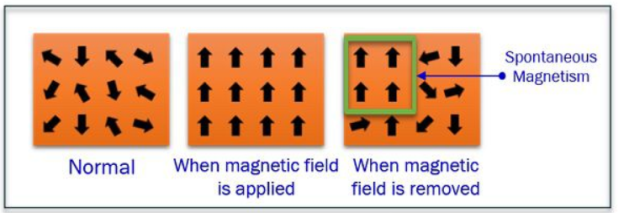
Ferromagnetic material
When force removes then the atomic magnetic moment again arranges themselves randomly but few of them still align parallel to each other.
Because of these atomic magnetic moments the substance becomes slightly magnetizes. This type of magnetism is known as the spontaneous magnetism.
For removing the spontaneous magnetism the reversed MMF applied to the material. The losses which occur because of the reversal of magnetism is known as the hysteresis losses.
Definition of Eddy Current Loss
The eddy current induces in the core of the transformer when the alternating flux links with them. The flux induces the EMF in the core because of which the circulating current develops. The circulating current cause losses in terms of heat which increases the temperature of the coil.
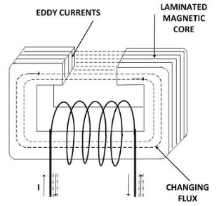
The eddy current losses are independent of load and hence known as the constant losses.