S2
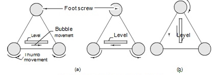
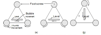
UNIT -1 THEODOLITE SURVEYQ1.What is theodolite?A1)- It is precise instrument for measuring angles in the horizontal and vertical planes.- It is accurate method or instrument used for measuring horizontal and vertical angles.- It can use in prolonging survey lines, and finding elevations etc.- It is also used for levelling.- The line of sight of instrument can be rotated 180 degree in vertical plane about its horizontal axis.Q2.What are the fundamental axes or parts of transit theodolite?A2)Following are part of theodolite (1)Telescope- Telescope in theodolite is used for focusing at which object piece and eye piece at other.- It rotates about horizontal axis in vertical plane.(2)Vertical circle- It is fitted to telescope and more simultaneously.- Graduation are there in each quadrant from 0 to 90 degree.(3)Index frame- It is also known as veriner frame or t frame.- It consists of two parts vertical and horizontal.- Horizontal arm is used to measure Vertical angle.- Vertical arm culps to lock telescope at certain level.(4)Standards- They are the frames which support telescope and it is rotated about vertical axis.- It is also called as A frame.(5)Upper plate- It gives support to standards.- It consists of two verinerwith magnifiers which are arranged diagonally.- Upper clamping screw with respect to tension screw which helps to fixing with the lower plate.(6)Lower plate- It contains scale on which 0 to 360 reading are graduate.- It is also called as scale plate.- It is attached to outer spindle.- It consists lower clamping screw.- If lower clamp is loosened and upper is tightened both plates can rotate together.- if the procedure is reversed that is lower clamp is tightened and upper loosened and then upper plate is movable and lower plate is fixed.7) Levelling head- It contain two parallel triangular plates known as tri batch plates.- Upper path that is upper tribatch used to level up per plates and telescope with help of leveling screw.- Lower part i.e. lower tribatch plate and is attached through tripod.8) Shifting head- It contain two parallel plates which are right angle to each other with one of them is parallel to trunnion axis.9) Tripod:- - It is just stand for theodolite which mounted over it.- Levelled position is required for tripod to give correct observations.- Steel shoes are there at the end of tripod leg.- These leg hold the ground strongly10) Plumb Bob- It is cone-shaped weight attached or tie with long thread.- These is used for entering of theodolite.11) Magnetic compass:-- It is in circular compass box in centre of upper plate and used for selecting meridian.Q3.Explain temporary adjustment of transit theodolite?Theodolite has two types of adjustments- temporary and permanent. Temporary adjustment is to be done at every station the instrument is set up. Permanent adjustments deal with the fundamental lines and relationships and should be done once in a while to ensure that the instrument is properly adjusted.The temporary adjustments are the following: (a) setting up and centring,(b) levelling, (c) focusing the eyepiece, and (d) focusing the objective. Setting Up and CentringThe following procedure is adopted for this operation.1. Remove the theodolite from its box carefully and fix it on a tripod kept over the station where the instrument is to be set up. The tripod legs should be well apart and telescope should be at a convenient height for sighting.2. Tie a plumb bob onto the hook provided at base. If there is no shifting head in the instrument, centre it by adjusting the tripod legs and shifting the instrument as a whole to bring the plumb bob over station mark. 3. To centre the plumb bob, shift the tripod legs radially ad circumferentially. Moving any leg radially shifts the plumb bob in direction of the leg. This does not affect the level status of instrument. Moving any leg circumferentially does not appreciably shift plumb. However, this movement tilts the instrument and affects the level of plate bubbles. By moving the legs the plumb bob is brought over the station mark at same time ensuring that the instrument is approximately level. This saves a lot of time for next operation of levelling. 4. If the instrument has a shifting head with a clamp, first centre the instrument using legs. Make the final adjustment by loosening the clamp and shifting the head to bring the plumb bob over station mark, .The starting step should be to first bring the plumb bob very close to the mark and then make the final adjustment using the legs or shifting head. LevellingAfter setting up and centring instrument, levelling is done. Levelling has to be done at every station the instrument being set up. By levelling the instrument, it is ensured that as the instrument is swung about the vertical axis, t he horizontal plate moves in a horizontal plane. The instrument may have a three screw or a four screw levelling head. The levelling operations differ slightly in these two cases as detailed in following sections. Most instruments have only one bubble tube, but some instruments have two bubble tubes set at right angles over plates. Three-screw levelling head When the theodolite has a three-screw levelling head the following procedure is selected. 1. Swing the theodolite and bring plate bubble parallel to any two of the foot screws. Centre the bubble by rotating the foot screws. To do this, hold foot screws by the uniband o reinge o each ch hand and rotate both either inwards or outwards [see Fig. 6.3(a)]. Also note that bubble moves in the direction of movement of the left thumb during this operation.Once bubble traverses (or comes to the central position from the graduation of the tube), swing instrument and bring the bubble over third foot screw. In this position, bubble tube is at right angles to the earlier position. Centre the bubble by rotating third foot screw alone.
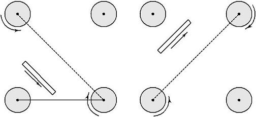
Fig. Three-foot-screw levelling head 3. Bring plate bubble to its previous position by swinging the instrument back. Check whether the bubble traverses. If it does not traverse, bring the bubble to centre using the two foot screws as before. 4. Repeat the procedure till bubble traverses in both these positions. 5. Swing the instrument t hrough 180 o and check whether bubble traverses. The bubble should traverse in all positions if the instrument has been properly adjusted. If two plate bubbles are provided [see Fig. 6.3(b)], the procedure is the same except that swinging the instrument through 90 is not required. When one plate level is kept parallel to a pair of foot screws, t he other plate level is over the third foot screw (in a perpendicular direction). The third foot screw is adjusted alternately by the same process using foot screws over which they are parallel. Four-screw levelling head When the theodolite has a four-screw levelling head, the following procedure is adopted. 1. After setting up and centring the theodolite, bring the plate level parallel to any one pair of diagonally opposite foot screws. Operate these foot screws to centre bubble (Fig. 6.4). 2. Swing the instrument to bring plate level parallel to the other pair of foot screws. Centre the bubble. 3. Swing it back to the previous position. Check whether the bubble traverses. If it does not, centre it with foot screws to which the level is parallel. 4. Swing it back, check position of the bubble, and repeat the procedure. 5. Once the bubble traverses in the two orthogonal positions, swing it through 180o . The bubble should traverse in this position If two plate levels are provided, procedure is the same. Bring one plate level parallel to a pair of opposite foot screws. The other pair will be parallel to the remaining pair of foot screws. There is no need to swing the instrument. Bring the bubble to central position alternately and check in the other positions.
Four-foot-screw levelling headQ4.Explain 3 screw levelling head?A4)Three-screw levelling head When the theodolite has a three-screw levelling head the following procedure is selected. 1. Swing the theodolite and bring plate bubble parallel to any two of the foot screws. Centre the bubble by rotating the foot screws. To do this, hold foot screws by the uniband o reigned o each ch hand and rotate both either inwards or outwards [see Fig. 6.3(a)]. Also note that bubble moves in the direction of movement of the left thumb during this operation. Once bubble traverses (or comes to the central position from the graduation of the tube), swing instrument and bring the bubble over third foot screw. In this position, bubble tube is at right angles to the earlier position. Centre the bubble by rotating third foot screw alone.
Q5.How to measures horizontal angles?A5)Measurement of horizontal angle1) To measure angle of ABC, instrument is set to B.2) Upper clamp is loosened and lower clamp is fixed.3) Telescope is turned and vernier A is a set O and Vernier B to 180°.4) Now lower clamp is loosened and tightened scope is pointed to A and bisect ranging rod at A.5) Now lower clamp is tightened and lower tangent screw is turned to perfectly bisect ranging rod at A.6) Now upper clamp is loosened and telescope is turned clockwise to bisect the C which is tightened at upper clamp.7) Now, vernier reading A and B is noted.8) Vernier A result in angle directly and vernier B result reading by subtracting initial reading from final reading.Q6.Explain repetition method?A6)It is define as method in which angle is measured in clockwise direction for any number of times is known as repetition method.Usually six times three repetition with face left and three with face right.ProcedureSet up instrument over Q and levelled with accurately with telescope in normal position. Set up Vernier A to 3600. Loosen the lower clamp direct the telescope to left hand ranging rod at P. exactly by using the upper clamp and lower tangent. The Vernier reading should be same. Loose upper clamp and turn the telescope in clockwise direction and bisect the right hand ranging rod at R exactly by using the upper clamp and upper slow motion screw. Read both Vernier. Let mean reading be 3002’ the object of reading both Vernier to obtain an approximate value of the angle. Leaving Vernier unchanged unclamp the lower plate and turn the telescope in clockwise direction bisect the ranging rod P exactly with lower clamp and lower tangent screw. Reading of Vernier should be same as before. Loose the upper clamp and turn the telescope in clockwise direction and bisect ranging rod at R exactly by using upper clamp and upper tangent screw. The Vernier now read twice the value of angle By the levelling Vernier clamp at 60040’ measure the angle third time. Read both the Vernier’s. Read final angle. Q7.How to measures vertical angles?A7) Measurement of vertical angle1) The zeros of Vernier are set to 0 degree to vertical circle.2) Telescope is den clamped.3) Plate bubble are brought to center with foot screw and altitude bubble is brought to centre by clip screw.4) Telescope in bisect to point A and measure the angle of elevation.5) Finally reading of vernier is noted and elevation angle is also noted.6) Now, face of instrument is changed and point A is bisected again and reading are noted.7) Telescope is lowered slowly and B is bisected to measure angle of depression.Q8.Explain methods of prolonging?A8) There are two methods of prolonging a given line such as AB (1) Fore sight method (2) Back Sight Method (1)Fore Sight Method. As shown in the fig.
i) Set up the theodolite on A and level it accurately . Bisect the point b correctly. Establish a point C at the line beyond B approximately by looking over the top of the telescope and accurately by sighting through telescope. ii) Shift the instrument to B ,take a fore sight at C and establish a point D in line beyond C. iii) Repeat the process until last point Z is reached. (2) Back Sight Method. As shown in the fig.
i) Set up the instrument at B and leve lthat accurately . ii) Take a back sight at A. iii) Tighten the upper and lower clamps, transit the telescope and establish a point C at the line beyond B. iv) Shift the theodolite to C ,back sight on B transit the telescope and establish a point D atline beyond C. Repeat the process until the last point ( Z) is established. Now if the instrument is in adjustment, the points A,B,C,D and Z will be in one line, which is straight but if it is not in adjustment i.e. line of collimation is not perpendicular to the horizontal axis ,then C’, D’ and Z’ will not be in a straight line.Q9.What are the types of theodolite?A9) Theodolites may be thoroughly portrayed into two sorts
1) Transit theodolite
2) Non-travel theodolite Q10.What are the uses of theodolite?A10) Uses:Used for measurement of horizontal and vertical angles Forming panels. Meteorology. Measuring and laying out angles and straight lines. Plumbing a column or building corner. Navigating. Laying out building corners and lines. Aligning wood frame walls.
|
|
|
Fore Sight Method |
|
Back Sight Method |
1) Transit theodolite
2) Non-travel theodolite Q10.What are the uses of theodolite?A10) Uses:
0 matching results found


