MICRO
UNIT – 2Microprocessor Architecture – 2 Q1) Explain data addressing modes?A1) The instructions are used to transfer the data from one register to another register, from the memory to the register, and from the register to the memory without any change in the content. Addressing modes in 8085 is divided into 5 groups − Immediate addressing modeHere, the 8/16-bit data is specified in the instruction itself as one of its operands. For example: MVI B, 40F means 40F is copied into register B. Register addressing modeHere, the data is copied from one register to another. For example: MOV B, A: means data in register A is copied to register B. Direct addressing modeHere, the data is directly copied from the given address to the register. For example: LDB 5008H: means the data at address 5008H is copied to register B. Indirect addressing modeHere, the data is transferred from one register to another by using the address pointed by the register. For example: MOV B, K: means data is transferred from the memory address pointed by the register K to the register B. Implied addressing modeHere, it doesn’t require any operand; the data is specified by the opcode itself. For example: CMP. Q2) Explain direct program memory addressing?A2) Direct Program Memory Addressing• Direct program memory addressing is what many early microprocessors used for all jumps and calls. • Direct program memory addressing is also used in high-level languages, such as the GOTO instruction. • The microprocessor uses this form of addressing, but not as often as relative and indirect program memory addressing are used.• The instructions for direct program memory addressing store the address with the opcode. For example, if a program jumps to memory location 10000H for the next instruction, the address (10000H) is stored following the opcode in the memory. • Figure shows the direct intersegment JMP instruction and the 4 bytes required to store the address 10000H.
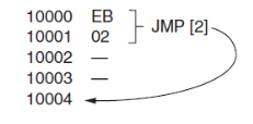
• This JMP instruction loads CS with 1000H and IP with 0000H to jump to memory location 10000H for the next instruction.• An intersegment jump is a jump to any memory location within the entire memory system.) The direct jump is often called a far jump because it can jump to any memory location for the next instruction. Q3) Explain relative program memory addressing?A3) Relative Program Memory Addressing• Relative program memory addressing is not available in all early microprocessors, but it is available to this family of microprocessors. The term relative means relative to the instruction pointer (IP). • For example, if a JMP instruction skips the next 2 bytes of memory, the address in relation to the instruction pointer is a 2 that adds to the instruction pointer. This develops the address of the next program instruction.• An example of the relative JMP instruction is shown below.
• The JMP instruction is a 1-byte instruction, with a 1-byte or a 2-byte displacement that adds to the instruction pointer. A 1-byte displacement is used in short jumps, and a 2-byte displacement is used with near jumps and calls. Both types are considered to be intra segment jumps. • An intra segment jump is a jump anywhere within the current code segment.Indirect Program Memory AddressingThe microprocessor allows several forms of program indirect memory addressing for the JMP and CALL instructions.
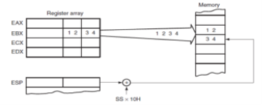
Fig 1 Instruction Table Q4) Explain stack memory addressing modes?A4) The stack plays an important role in all microprocessors. It holds data temporarily and stores the return addresses used by procedures. The stack memory is a LIFO (last-in, first-out) memory, which describes the way that data are stored and removed from the stack. [Ref.4]• Data are placed onto the stack with a PUSH instruction and removed with a POP instruction. • The CALL instruction also uses the stack to hold the return address for procedures and a RET (return) instruction to remove the return address from the stack.• The stack memory is maintained by two registers: the stack pointer (SP) and the stack segment register (SS). Whenever a word of data is pushed onto the stack, the high-order 8 bits are placed in the location addressed by SP – 1. The low-order 8 bits are placed in the location addressed by SP – 2. The SP is then decremented by 2 so that the next word of data is stored in the next available stack memory location.
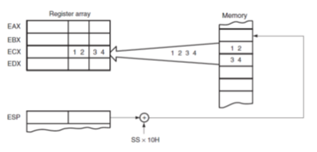
Fig 2 Stack Memory Location• The SP register always points to an area of memory located within the stack segment. The SP register adds to SS x 10h to form the stack memory address in the real mode. • Whenever data are popped from the stack, the low-order 8 bits are removed from the location addressed by SP. The high-order 8 bits are removed from the location addressed by SP+1. The SP register is then incremented by 2.
Fig 3 Stack memory Location• PUSH and POP store or retrieve words of data—never bytes—in the 8086 microprocessors.
Fig 4 POP and PUSH instruction Table• Data may be popped off the stack into any register or any segment register except CS. The reason that data may not be popped from the stack into CS is that this only changes part of the address of the next instruction. Q5) Explain flat mode memory? A5) On 32-bit processors, Windows and Linux use the so-called protected mode flat memory model.Under flat memory model,Entire address space is described by a 32-bit segment, which provides 232 = 4 gigabytes of address space. Program can access up to 4 gigabytes of virtual or physical memory.In protected mode,Segment registers contain selector values rather than actual physical segment addresses. Selector values cannot be calculated by the program; they must be obtained by calling the operating system. Programs that update segment values or attempt to address memory directly do not work in protected mode.
Fig 5 Flat Mode Model Protected ModeThe instruction pointer is 32 bits in size EIP can indicate any machine instruction anywhere in the 4 GB of memory. The segment registers still exist and define where 4 GB of program-accessible memory resides in physical or virtual memory The segment registers are now considered part of the operating system, you can neither read nor change them directly. When 32-bit program executes, it has access to 4-gig address space. Any general-purpose register by itself can specify any memory location in the entire memory address space of the 4 billion memory locations Attempting to actually read or write certain locations in your own program can be forbidden by the OS and will trigger an error. Challenges in programming for protected mode flat model are based on understanding the operating system, its requirements, and restrictions. Q6) Explain the page directory and page table?A6) To convert a 32-bit linear address into a 32-bit physical address, we need to understand that the most significant 20 bits of the linear address indicate the linear page number, while the least significant 12 bits of the linear address indicate the offset within this page. The offset should remain the same but the linear page number has to be converted into a physical page number.
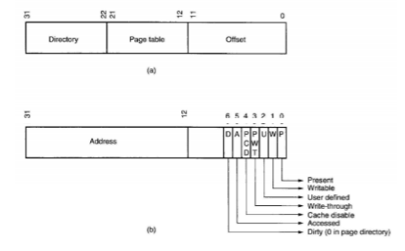
Fig 6 Page Directory and Page Address Each page directory entry is a physical address pointing to a page table, which contains page table entries. Each page table contains 1024-page table entries, each of which is 4 bytes (32 bits). This means that each page table is 4 K bytes long. Each page table entry points to the starting physical address of a page in memory. This means that if we have one page directory and 1024-page tables, then we have a total of 1M table entries or 1 M pages. Since each page is 4K bytes long, this will cover a total of 4G bytes of maximum physical memoryThe figure below Part (a) shows the linear address (generated by the software) and how it selects one of the 1024-page directory entries from the page directory (using the left most 10 bits) and then selects one of the 1024-page table entries (using the next 10 bits). Part (b) of the figure shows the offset. page table entry, which contains the physical number that must be associated with the example, the linear addresses 00000000h-00000FFFh access the first page directory entry, and the first page table entry. Notice that one page is a 4K-byte address range.
Fig 7(a) Linear Address (b) Off-setSo, if that page table entry contains 00100000h, then the physical address of this page is 00100000h-00100FFFh for linear address 00000000h-00000FFFh. This means that when the program accesses a location between 00100000H and 00100FFFh, the microprocessor physically addresses location 00100FFFH.
|
|
|
|
|
|
|
|
|
0 matching results found


