In Verilog, invoke a VHDL entity by entering its name (identifier) and its ports in the Verilog module. The parameters of the module should match the type and port directions of the entity. VHDL ports that can be mapped to Verilog modules are: in, out, and inout; buffer, in some simulators, is not allowed. Only the entire VHDL entity can be made visible to the Verilog module. Invoking a VHDL Entity From a Verilog Module //This is the Verilog module module mixed (a, b, c, d); input a, b; output c, d; ........... VHD_enty V1 (a, b, c, d); /*The above module VHD_enty is the VHDL entity to be invoked in this module*/ ........... endmodule --This is the VHDL entity library IEEE; use IEEE.STD_LOGIC_1164.ALL; entity VHD_enty is port (x, y : in std_logic; O1, O2 : out std_logic); end VHD_enty; architecture VHD_enty of VHD_enty is begin ........... end VHD_enty; . The simulator looks first in the Verilog module to see if there are any Verilog modules by the name of VHD_enty. If it could not find one, the simulator looks in the VHDL entities. When the simulator finds an entity with the name VHD_enty, it binds this entity to the Verilog module. In the above example, input a is passed to input port x; input b is passed to input y. The VHDL entity calculates the outputs O1 and O2; these two outputs are passed to the Verilog outputs c and d, respectively. Invoking a VHDL module is very similar to invoking a function or a task.
|
In the VHDL module, declare a component with the same name as the Verilog module to be invoked; the name and port modes of the component should be identical to the name and input/output modes of the Verilog module. Remember that Verilog is case sensitive, so be sure to match the case.
Invoking a Verilog Module From a VHDL Module -- This is the VHDL Project library IEEE; use IEEE.STD_LOGIC_1164.ALL; entity Ver_VHD is port (a, b : in std_logic; c : out std_logic); end Ver_VHD; architecture Ver_VHD of Ver_VHD is component V_modl port (x, y : in std_logic; z : out std_logic); -- The name of the Component V_modl should be -- identical to the name of the -- Verilog module; also, the ports should be -- identical in name and mode -- with the inputs and outputs of the Verilog module end component; ....... end Ver_VHD; //This is the Verilog module module V_modl (x, y, z); input x, y; output z; endmodule the component statement in the VHDL module component V_modl port (x, y : in std_logic; z : out std_logic); end component; declares a component by the name of V_modl with two input ports, x and y, and an output port z. The Verilog module V_modl has the same name (including the case) as the component and identical inputs and outputs. Accordingly, the Verilog module V_modl is bound to the VHDL component V_modl.
|
--This is the Verilog module module Full_Adder1 (x, y, cin, sum, carry); input x, y, cin; output sum, carry; wire c0, c1, s0; HA H1 (y, cin, s0, c0); HA H2 (x, s0, sum, c1); // Description of HA is written in VHDL in the entity HA or (carry, c0, c1); endmodule library IEEE; use ieee.std_logic_1164.all; entity HA is --For correct binding between this VHDL code and the above --Verilog code, the entity has to be named HA. port (a, b : in std_logic; s, c : out std_logic); end HA; architecture HA_Dtflw of HA is begin s <= a xor b; c <= a and b; end HA_Dtflw;
Referring to the Verilog statement
HA H1 (y, cin, s0, c0);
invokes a module by the name of HA. Because there is no Verilog module by this name, the simulator looks at the VHDL modules attached to the Verilog modules. The simulator finds an entity by the name of HA; accordingly, this entity and its bound architecture(s) are made visible to the Verilog module. The architecture here is a data-flow description of a half adder. The inputs y and cin are passed to the input ports of HA, a and b. The VHDL entity calculates the outputs s and c as:
s <= a xor b; c <= a and b;
The outputs of the entity s and c are passed to the outputs of the module HA, s0 and c0.
|
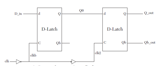
//This is the Verilog module module D_Master (D_in, clk, Q_out, Qb_out); input D_in, clk; output Q_out, Qb_out; wire Q0, Qb, clkb; / wire statement here can be omitted./ assign clkb = ~ clk; assign clk2 = ~ clkb; D_Latch D0 (D_in, clkb, Q0, Qb); //D_Latch is the name of a VHDL entity describing a D-Latch D_Latch D1 (Q0, clk2, Q_out, Qb_out); endmodule library IEEE; use IEEE.STD_LOGIC_1164.ALL; entity D_Latch is --The entity has the same name as --the calling Verilog module port (D, E : in std_logic; Q, Qbar : buffer std_logic); end D_Latch; architecture DL_DtFl of D_Latch is --This architecture describes a D-latch using --data-flow description constant Delay_EorD : Time := 9 ns; constant Delay_inv : Time := 1 ns; begin Qbar <= (D and E) nor (not E and Q) after Delay_EorD; Q <= not Qbar after Delay_inv; end DL_DtFl; |
A basic VHDL does not have built-in gates such as AND, OR, and XOR, unless the user attaches a vendor’s package that contains a description of the gates. Standard Verilog, on the other hand, has built-in descriptions of primitive gates of which we can take advantage. Using mixed-language description, a Verilog module is invoked in the VHDL module, and the gates that we want to use are instantiated.
Mixed-Language Description of an AND Gate
library IEEE; use IEEE.STD_LOGIC_1164.ALL; use IEEE.STD_LOGIC_ARITH.ALL; --This is the VHDL module entity andgate is port (a, b : in std_logic; c : out std_logic); end andgate; architecture andgate of andgate is component and2 --For correct binding with the Verilog module, --the name of the component should be identical --to that of the Verilog module. port (x, y : in std_logic; z : out std_logic); --The name of the ports should be identical to the name --of the inputs/outputs of the Verilog module. end component; begin g1 : and2 port map (a, b, c); end andgate; //This is the Verilog module module and2 (x, y, z); input x, y; output z; and( z, x , y); endmodule
|
|
Mixed-Language Description of a JK Flip-Flop
library IEEE; use IEEE.STD_LOGIC_1164.ALL; entity JK_FF is Port (Jx, Kx, clk, clx : in std_logic; Qx, Qxbar : out std_logic); end JK_FF;
architecture JK_FF of JK_FF is --The JK flip flop is declared as a component component jk_verilog port(j, k, ck, clear : in std_logic; q, qb : out std_logic); end component; begin jk1 : jk_verilog port map (Jx, Kx, clk, clx, Qx, Qxbar); end JK_FF; module jk_verilog (j, k, ck, clear, q, qb); // The module name jk_verilog matches // the name of the VHDL components input j, k, ck, clear; output q, qb; --The input and output ports match those of the --VHDL component, jk_verilog reg q, qb; reg [1:0] JK; always @ (posedge ck, clear) begin if (clear == 1) begin q = 1’b0; qb = 1’b1; end else begin JK = {j, k}; case (JK) 2’d0 : q = q; 2’d1 : q = 0; 2’d2 : q = 1; 2’d3 : q = ~q; endcase qb = ~q; end end endmodule |
Mixed-Language Description of Three-Bit Counter with Clear
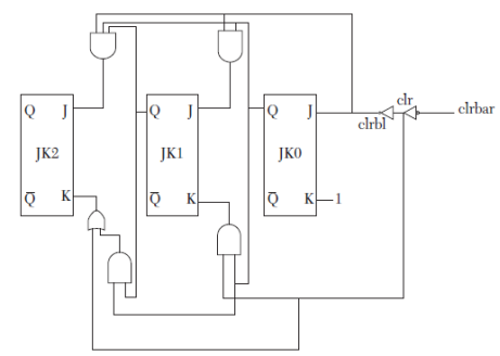
library IEEE; use IEEE.STD_LOGIC_1164.ALL; entity countr_3 is port (clk, clrbar : in std_logic; q, qb : inout std_logic_vector (2 downto 0)); end countr_3; architecture CNTR3 of countr_3 is component JK_FF port (I1, I2, I3 : in std_logic; O1, O2 : inout std_logic); end component; component inv
port (I1 : in std_logic; O1 : out std_logic); end component; component and2 port (I1, I2 : in std_logic; O1 : out std_logic); end component; component or2 port (I1, I2 : in std_logic; O1 : out std_logic); end component; signal J1, K1, J2, K2, clr, clrb1, s1, high : std_logic; begin high <= ‘1’; FF0 : JK_FF port map (clrb1, High, clk, q(0), qb(0)); A1 : and2 port map (clrb1, q(0), J1); inv1 : inv port map (clr, clrb1); inv2 : inv port map (clrbar, clr); r1 : or2 port map (q(0), clr, K1); FF1 : JK_FF port map (J1, K1, clk, q(1), qb(1)); A2 : and2 port map (q(0), q(1), s1); A3 : and2 port map (clrb1, s1, J2); r2 : or2 port map (s1, clr, K2); FF2 : JK_FF port map (J2, K2, clk, q(2), qb(2)); end CNTR3 ;
module and2 (I1, I2, O1); //This Verilog module represents an AND function
input I1, I2; output O1; assign O1 = I1 & I2; endmodule
module inv (I1, O1); //This Verilog module represents an INVERT function input I1; output O1; assign O1 = ~I1; endmodule module or2 (I1, I2, O1); //This Verilog module represents an OR function
input I1, I2; output O1; assign O1 = I1 | I2; endmodule
module JK_FF (I1, I2, I3, O1, O2); //This Verilog module represents a JK flip-flop.
input I1, I2, I3; output O1, O2; reg O1, O2; reg [1:0] JK; initial begin O1 = 1’b0; O2 = 1’b1; end
always @ (posedge I3) begin JK = {I1, I2}; case (JK) 2’d0 : O1 = O1; 2’d1 : O1 = 0; 2’d2 : O1 = 1; 2’d3 : O1 = ~O1; endcase
O2 = ~O1; end endmodule |


