|
|
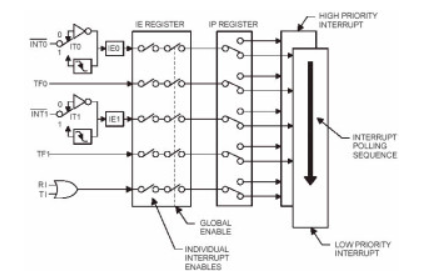
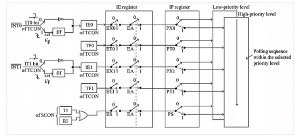
Bit Address | AF
| AE | AD | AC | AB | AA | A9 | A8 |
Bit Details | EA | X | x | ES | ET1 | EX1 | ET0 | EX0 |
Bit Details | High Value(1) | Low Value(0) |
EA | Least significant 5 bits can decide enable or disable these five interrupts | Disable all five interrupts . It just ignores the rest five bits |
ES | Enable Serial Port Interrupt | Disable Serial Port Interrupt |
ET1 | Enable Timer1 Interrupt | Disable Timer1 Interrupt |
EX1 | Enable external interrupt1 | Disable external interrupt1 |
ET0 | Enable Timer0 interrupt | Disable Timer0 Interrupt |
EX0 | Enable external interrupt 0 | Disable external interrupt 0 |
Bit Address | 8F | 8E | 8D | 8C | 8B | 8A | 89 | 88 |
Bit Details | TF1 | TR1 | TF0 | TR0 | IE1 | IT1 | IE0 | IT0 |
Bit Details | High Value(1) | Low Value(0) |
IT0 | Set INT0 as negative edge triggered input | Set INT0 as active low level triggered input. |
IT1 | Set INT1 as negative edge triggered input | Set INT1 as active low level triggered input. |
IE0 | This will be 1. When INT0 is activated as level triggered | This will be 0 when INT0 is activated as edge triggered |
IE1 | This will be 1. When INT1 is activated as level triggered | This will be 0 when INT1 is activated as edge triggered |
TR0 | Set Timer0 as run mode | Set Timer0 as stop mode. |
TR1 | Set Timer1 as run mode | Set Timer1 as stop mode |
TF0 | High when Timer0 overflow occurs | After resetting the timer 0 this will also be changed to 0 state |
TF1 | High when Timer1 overflow occurs | After resetting the timer T1 this will also be changed to 0 state |
Bit Address | 9F | 9E | 9D | 9C | 9B | 9A | 99 | 98 |
Bit Details | SM0 | SM1 | SM2 | REN | TB8 | RB8 | TI | RI |
Bit Details | Description |
SM0 | This is Serial Port Mode0 shift register |
SM1 | This is Serial Port Mode 1 (8-bit UAR + variable) |
SM2 | Enable multiprocessor communication in the mode 2 or 3 |
REN | Set or reset by the software to enable or disable the Reception |
TB8 | It indicates the 9th bit that will be transmitted in mode 2 or 3. It can be set or reset by software |
RB8 | In mode 2 or 3 the 9th bit was received in mode 1. |
TI | The transmission interrupt flag . It can be set by hardware |
RI | The receiver interrupt flag . It can be set by hardware |
|
|
|
|
M0 | M1 | Mode | Operating Mode |
0 | 0 | 0 | 13-bit timer mode. 8 bit timer/counter THx and TLx as –bit prescalar |
0 | 1 | 1 | 16-bit timer mode , 16-bit timers/counters THx and TLx as 5-bit prescalar |
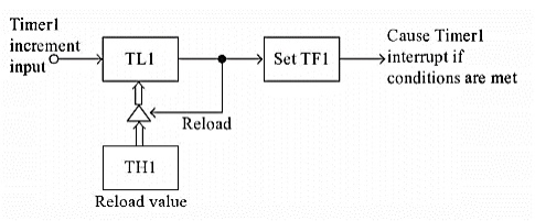
1 | 0 | 2 | 8-bit auto reload mode, 8-bit auto reload timer/counter; THx holds a value which is to be reloaded into TLx each time it overflows |
1 | 1 | 3 | Split timer mode |
TF1 | TR1 | TF0 | TR0 | IE1 | IT1 | IE0 | IT0 |
Bit | Symbol | Functions |
7 | TF1 | Timer1 overflow flag. Set when timer rolls from all 1’s to 0 |
6 | TR1 | Timer 1 run control bit. Set to 1 by programmer to enable timer to count. |
5 | TF0 | Timer 0 overflow flag |
4 | TR0 | Timer 0 run control bit |
3 | IE1 | External Interrupt 1 edge flag |
2 | IT1 | External Interrupt 1 signal type control bit |
1 | IE0 | External Interrupt 0 edge flag |
0 | IT0 | External Interrupt 0 signal type control bit |
Timer | Timer1 Mode | Timer0 Mode | ||||||
Bit Details | Gate (G) | C/T | M1 | M0 | Gate (G) | C/T | M1 | M0 |
|
Bit Details | High Value(1) | Low Value(0) |
C/T | Configure for the Counter operations | Configure for the Timer operations |
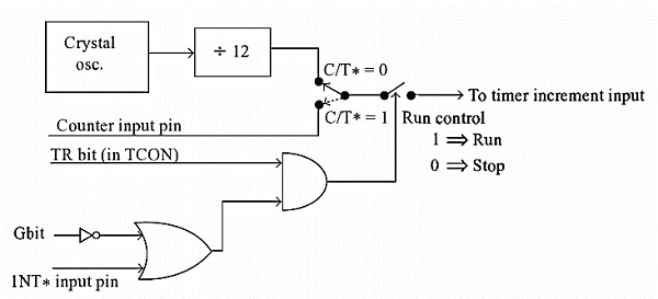
Gate (G) | Timer0 or Timer1 will be in RunMode when TRX bit of TCON register is high. | Timer0 or Timer1 will be in RunMode when TRX bit of TCON register is high and INT0 or INT1 is high. |
Bit Details | 00 | 01 | 10 | 11 |
M1 M0 | This is for Mode 0. (8-bit timer/counter, with 5-bit pre-scaler) | This is Mode 1. (16-bit timer/counter) | This is Mode 3 (8-bit auto reload-timer/counter) | This is Mode 3 (The function depends on Timer0 or Timer1) |
|
|
|
