Back to Study material
BEE

UNIT 1DC and AC circuits Q1) Explain Ohms law?A1) Ohm's Law states that the current flowing in a circuit is directly proportional to the applied potential difference and inversely proportional to the resistance in the circuit.By doubling the voltage across a circuit, the current will also double. However, if the resistance is doubled the current will fall by half.In this mathematical relationship the unit of resistance is measured in Ohms.

 Ohm's law can be expressed in a mathematical form:V=IRWhere:    V = voltage expressed in Volts    I = current expressed in Amps    R = resistance expressed in OhmsThe formula can be manipulated so that if any two quantities are known the third can be calculated.

I=V/R

R=V/I

 Q2) Explain Kirchhoff’s law?A2)KCL:The algebraic sum of currents meeting at a junction or node in a electric circuit is zero or the summation of all incoming current is always equal to summation of all outgoing current in an electrical network.Explanation  


Assuming the incoming current to be positive and outgoing current negative we have

I e incoming current = ∑ outgoing current thus, the above Law can also be stated as the sum of current flowing towards any junction in an electric circuit is equal to the sum of currents flowing away from that junction

 Kirchhoff’s Voltage Law (KVL)statement: the algebraic summation of all Voltage in any closed circuit or mesh of loop zero.i.e.  ∑ Voltage in closed loop = 0 the summation of the Voltage rise (voltage sources) is equal to summation of the voltage drops around a closed loop in 0 circuit for explanation from heredetermination of sigh and direction of currents (Don’t write in exams just for understanding) 

  current entering a resistor is +ve and leaving should be –venow

 Q3) Two cells having emf of 10 V and 8V, and internal resistance of 1 Ω(each) are connected as shown with an external resistance of 8 Ω. Find the current flowing through the circuit.A3)


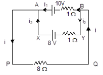
Suppose that a current i flows through the external resistance (8 Ω) and it divides

Using KCL , i1 + i2 = i

into two branches at the node B as i1and i2 

Using KVL,

For Loop ABYXA :

10 + (i1)1 + (i i1) 1 8 = 0

For Loop ABQPA :

10 + (i1)1 + (i)8 = 0

Solving, we get,

i = 18/17 A ≈ 1.06A

i1 = 10 8i

= (10 8.54)A

= 1.52 A.
i2 = i i1

= 0.46 A

The negative sign for i2 means that its direction is opposite to the direction that we had assumed.Q4) Explain the analysis of series, parallel and series -parallel circuits?A4)Series connection


 Parallel connection: The basic idea of a “parallel” connection, on the other hand, is that all components are connected across each other’s leads. In a purely parallel circuit, there are never more than two sets of electrically common points, no matter how many components are connected. There are many paths for current flow, but only one voltage across all components: 


 Q5) Find the equivalent resistance, REQ for the following resistor combination circuit.A5)

complex resistor combination

 Again, at first glance this resistor ladder network may seem a complicated task, but as before it is just a combination of series and parallel resistors connected together. Starting from the right hand side and using the simplified equation for two parallel resistors, we can find the equivalent resistance of the R8 to R10 combination and call it RA.

ra resistor combination


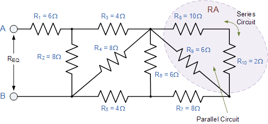
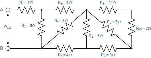
Ra = R9 x (R8 + R10)/ R9 + R8 + R10 = 6 x (10+2)/ 6 + 10 +2 = 4 Ω

RA is in series with R7 therefore the total resistance will be RA + R7 = 4 + 8 = 12Ω as shown.

rb resistor combination circuit

 This resistive value of 12Ω is now in parallel with R6 and can be calculated as RB.

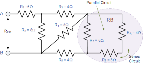
Rb = R6 x(Ra + R7)/ R5 + Ra + R7 = 6 x (4 +8) / 6 +4 +8 = 4Ω

   RB is in series with R5 therefore the total resistance will be RB + R5 = 4 + 4 = 8Ω as shown.

rc resistor combination circuit

 This resistive value of 8Ω is now in parallel with R4 and can be calculated as RC as shown.

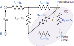
Rc = R4 x (RB + R5) / R4 + RB + R5 = 8 x (4 + 4) / 8 + 4 + 4 = 4 Ω

RC is in series with R3 therefore the total resistance will be RC + R3 = 8Ω as shown.

rd resistive combination

 This resistive value of 8Ω is now in parallel with R2 from which we can calculated RD as:

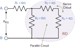
Rd = R2 x (Rc + R3)/ R2 + Rc + R3 = 8 x (4 + 4) / 8 + 4 + 4 = 4 Ω

RD is in series with R1 therefore the total resistance will be RD + R1 = 4 + 6 = 10Ω as shown.

final equivalent resistance

 Then the complex combinational resistive network above comprising of ten individual resistors connected together in series and parallel combinations can be replaced with just one single equivalent resistance ( REQ ) of value 10Ω. Q6) Explain the generation of sinusoidal voltage?A6)
  • When a single- phase supply is connected to an AC motor does not generate a rotating magnetic field, single phase motors require extra circuits for working, but such electric motors are rare over in rating of 10 kW.
  • In every cycle, a single- phase system voltage achieves a peak-value two times; the direct power is not stable.
  • Single Phase Waveform

    Single Phase Waveform 
  • A load with single-phase can be power-driven from a three-phase sharing transformer in two techniques. One is with the connection between two phases or with connection among one phase and neutral.
  • These two will give dissimilar voltages from a given power supply. This type of phase supply provides up to 230V.
  • The applications of this supply mainly use for running the small home appliances like air conditioners, fans, heater, etc.
  •  Q7) What is the frequency of the generated voltage?A7)The frequency of the generated voltage depends upon the number of field poles and on the speed at which the field poles are rotated. one complete cycle of voltage is generated in an armature coil when a pair of field poles passes over the coil.P = total number of field poles.p = pair of field poles N = speed of the field in r.p.m.n = speed of field poles in r.p.s.f = frequency of the generated voltage in Hz. 

    N/60 = n

    P/2 = p

     In one revolution of the rotor, an armature coil is cut by P/2 north poles and P/2 south poles. Since one cycle is generated in an armature coil when the pair of field poles passes over the coil, the number of cycles generated in one revolution of the rotor will be equal to the number of pars of the poles.  Q8) What is average value?A8) The term "average" usually encompasses several ways to measure what value best represents a sample. There are various measurements that are used and at times the term and measurement used depends on the situation.A statistician or mathematician would use the terms mean and average to refer to the sum of all values divided by the total number of values, what you have called the average. The quantity obtained by adding the largest and smallest values and dividing by 2, statisticians call the midrange. There are times however that this is called the mean.  Q9) What is root mean square value?A9)


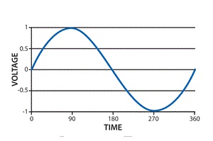
    The RMS value of AC current is equal to the steady state DC current that required to produce the same amount of heat produced by ac current provided that resistance and time for which these currents flows are identical

    I rms =  

     Q10) Explain peak and average value?A10)

     Peat to peak value: The value of an alternating quantity from its positive peak to negative peak

     Average Value:

     The arithmetic mean of all the value over complete one cycle is called as average value

    =

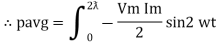
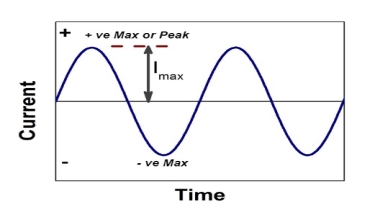
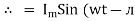
    For the derivation we are considering only hall cycle.

     Thus varies from 0 to

    i = Im   Sin

    Solving

    We get

    Similarly, Vavg=

    The average value of sinusoid ally varying alternating current is 0.636 times maximum value of alternating current. Q11) Explain the phasor representation of alternating values?A11)3 Basic element of AC circuit.  1] Resistance2] Inductance 3] Capacitance  Each element produces opposition to the flow of AC supply in a forward manner.Reactance
    1. Inductive Reactance (XL)

                 It is opposition to the flow of an AC current offered by the inductor.

    XL = ω L    But     ω = 2 F

    XL = 2 F L

                                      It is measured in ohm

    XLFInductor blocks AC supply and passes dc supply zero


    2.     Capacitive Reactance (Xc)

                    It is opposition to the flow of ac current offered by the capacitor

    Xc =

                                       Measured in ohm

    Capacitor offers infinite opposition to dc supply 


    Impedance (Z)

    The ac circuit is to always pure R Pure L and pure C it well attains the combination of these elements. “The combination of R1 XL and XC is defined and called as impedance represented as 

                                               Z = R +i X

                                              Ø = 0

      only magnitude

    R = Resistance, i = denoted complex variable, X =Reactance XL or Xc


    Polar Form

    Z   = L I

    Where =

    Measured in ohm

    Power factor (P.F.)


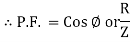
    It is the cosine of the angle between voltage and current

    If Ɵis –ve or lagging (I lags V) then lagging P.F.

    If Ɵ is +ve or leading (I leads V) then leading P.F.

    If Ɵ is 0 or in-phase (I and V in phase) then unity P.F. Q12) Explain the ac circuit containing pure inductance?A12)


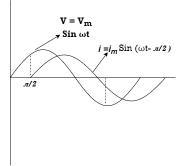
    Consider pure Inductor (L) is connected across alternating voltage. Source

    V = Vm Sin ωt

    When an alternating current flow through inductance it setups alternating magnetic flux around the inductor.

    This changing the flux links the coil and self-induced emf is produced

    According to faradays Law of E M I


    e =

    at all instant applied voltage V is equal and opposite to self-induced emf [ Lenz's law]

    V = -e

    =

    But V = Vm Sin ωt


    dt

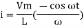
    Taking integrating on both sides
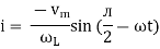
    dt

    dt

    (-cos )

    but sin (– ) = sin (+ )

    sin ( - /2)

    And Im=


    /2)

    /2

    = -ve

    = lagging

    = I lag v by 900


      Waveform: 


     Phasor:


    Power P = Ѵ. I

    = Vm sin wt    Im sin (wt /2)

    = Vm Im Sin wt Sin (wt – /s)

    And

    Sin (wt - /s) =  - cos wt        

    Sin (wt – ) = - cos

    sin 2 wt    from and

    The average value of sin curve over a complete cycle is always zero

    Pavg = 0