|
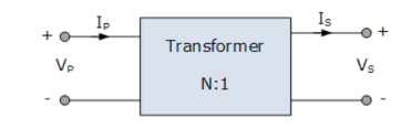
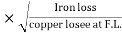
 phaseAcc to construction: core and shell typeAcc to 0/P : step up and step down Q4) Explain the emf equation of transformer?A4)A transformer basically consists of two coils wound around a common soft iron core. When an alternating voltage ( VP ) is applied to the primary coil, current flows through the coil which in turn sets up a magnetic field around itself, called mutual inductance, by this current flow according to Faraday’s Law of electromagnetic induction.The strength of the magnetic field builds up as the current flow rises from zero to its maximum value which is given as dΦ/dt.
|
emf = turns x rate of change E = N dɸ/dt
E = N x w x ɸ max x cos (wt)
Emax = N w ɸ max
Erms = Nw/ | ||
= 2 π / Erms = 4.44 fN x ɸ max | ||


 as the i/p supply is constant in magnitude
  the flux set up will be constant and
  core losses are also constant.
|
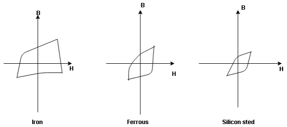
 the selection of magnetic material for the construction of core depends upon Hysteresis loop of that material having tall and narrow Hysteresis loop is selected for the T/F core
 silicon SteelHysteresis loss depends on fold factor PH = KH. Bm1.67 F
  V – watts Where KH = constant (Hyst)Bm = max Flux densityF = Frequency
 = Volume of core.2. Reedy current loss :This loss is due to the flow of reedy (circular) current in the core caused by induced emf in corePE = Ke Bm2 f2 t2 v – watts Where Ke = reedy current const.t = thickness of coreIt can be reduced by using stacks of laminations instead of solid coreB] Copper loss : PCU The Copper loss is due to resistance of the primary and secondary winding It is load dependent / current dependent loss
As load on a transformer is variable (changing) Primary secondary Total C is loss = I12R12 + I22 R22 | ||
Copper loss depends upon load on T/F and is proportional to square of load current or KVA rating of transformer
F.L = full load
= (0.5)2 PCU F.L. Or PCu ( | ||


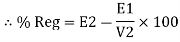
Find no load vtg E2 remove the load and measure the reading of V2 meter ew will get n load vtg E2
Now connect load and measure V2 this is now the load voltage
For each reading E2 will be same but V2 will change acc. To load
|

|
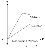
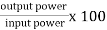
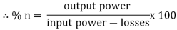
Efficiency: it is the ratio output power to input power of transformer
Output power = input power – total loss
| ||||
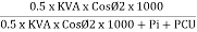
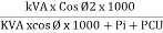
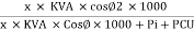
O/P power = KVA Or = V2 Losses = Pi + PCU (F.L) = iron + copper loss
| ||||
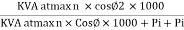
Maximum efficiency – for numerical: The efficiency of T/F is maximum when copper loss equates iron loss this is the condition for max efficiency ie Pi = PCU
Where KVA at max n given = Full load KVA
| ||||


Find no load vtg E2 remove the load and measure the reading of V2 meter ew will get n load vtg E2
Now connect load and measure V2 this is now the load voltage
For each reading E2 will be same but V2 will change acc. To load
|


|

Efficiency : it is the ratio output power to input power of transformer
Output power = input power – total loss
O/P power = KVA Or = V2 Losses = Pi + PCU (F.L) = iron + copper loss
|


Maximum efficiency – for numerical: The efficiency of T/F is maximum when copper loss equates iron loss this is the condition for max efficiency ie Pi = PCU
Where KVA at max n given = Full load KVA |